1993 CHEVROLET PLYMOUTH ACCLAIM trunk
[x] Cancel search: trunkPage 1287 of 2438
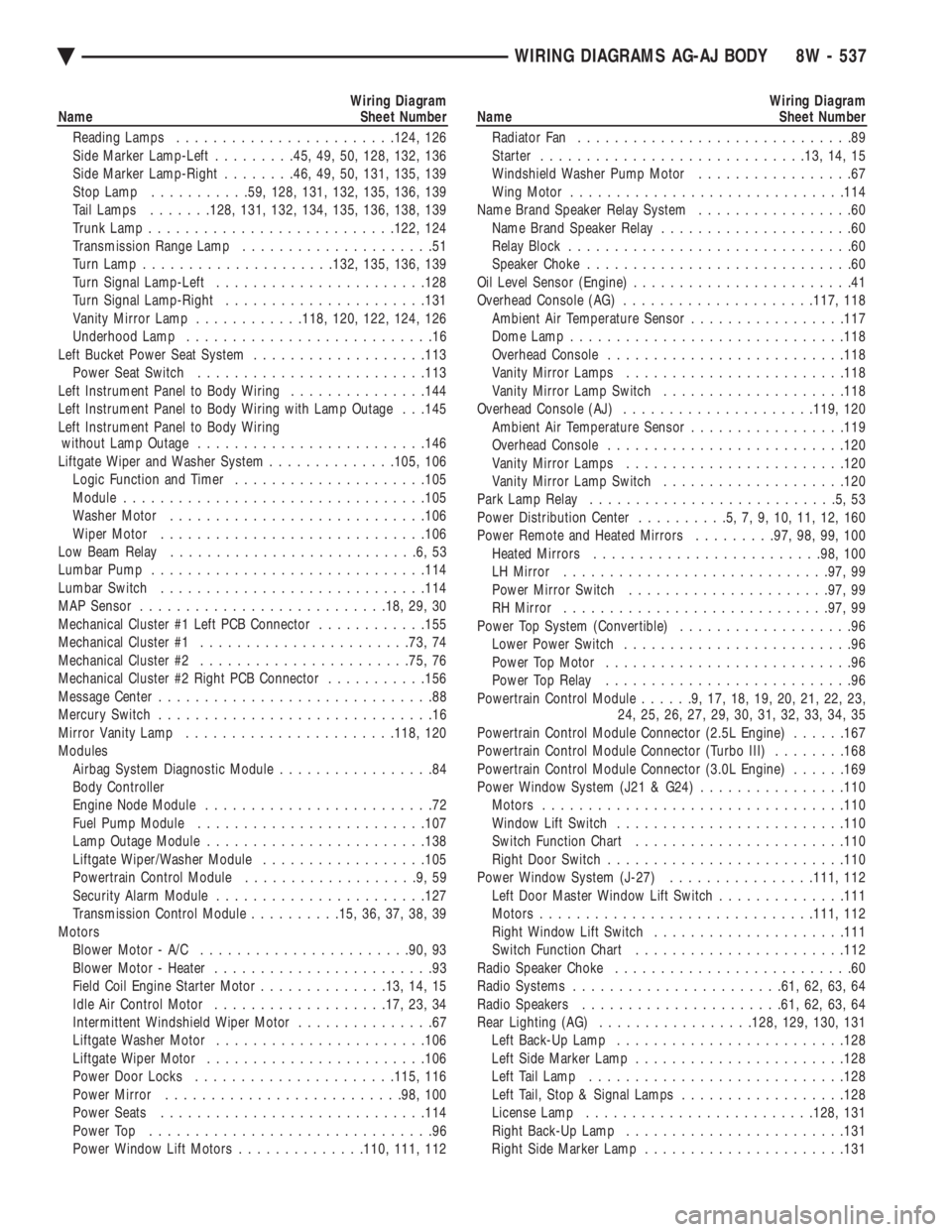
Wiring Diagram
Name Sheet Number
Reading Lamps ....................... .124, 126
Side Marker Lamp-Left .........45, 49, 50, 128, 132, 136
Side Marker Lamp-Right ........46, 49, 50, 131, 135, 139
Stop Lamp .......... .59, 128, 131, 132, 135, 136, 139
Tail Lamps .......128, 131, 132, 134, 135, 136, 138, 139
Trunk Lamp .......................... .122, 124
Transmission Range Lamp .....................51
Turn Lamp .................... .132, 135, 136, 139
Turn Signal Lamp-Left ...................... .128
Turn Signal Lamp-Right ..................... .131
Vanity Mirror Lamp ............118, 120, 122, 124, 126
Underhood Lamp ...........................16
Left Bucket Power Seat System ...................113
Power Seat Switch ........................ .113
Left Instrument Panel to Body Wiring ...............144
Left Instrument Panel to Body Wiring with Lamp Outage . . .145
Left Instrument Panel to Body Wiring without Lamp Outage ........................ .146
Liftgate Wiper and Washer System ..............105, 106
Logic Function and Timer .................... .105
Module ................................ .105
Washer Motor ........................... .106
Wiper Motor ............................ .106
Low Beam Relay ...........................6,53
Lumbar Pump ............................. .114
Lumbar Switch ............................ .114
MAP Sensor .......................... .18, 29, 30
Mechanical Cluster #1 Left PCB Connector ............155
Mechanical Cluster #1 ...................... .73, 74
Mechanical Cluster #2 ...................... .75, 76
Mechanical Cluster #2 Right PCB Connector ...........156
Message Center ..............................88
Mercury Switch ..............................16
Mirror Vanity Lamp ...................... .118, 120
Modules Airbag System Diagnostic Module .................84
Body Controller
Engine Node Module .........................72
Fuel Pump Module ........................ .107
Lamp Outage Module ....................... .138
Liftgate Wiper/Washer Module ..................105
Powertrain Control Module ...................9,59
Security Alarm Module ...................... .127
Transmission Control Module ..........15, 36, 37, 38, 39
Motors Blower Motor - A/C ...................... .90, 93
Blower Motor - Heater ........................93
Field Coil Engine Starter Motor ..............13, 14, 15
Idle Air Control Motor .................. .17, 23, 34
Intermittent Windshield Wiper Motor ...............67
Liftgate Washer Motor ...................... .106
Liftgate Wiper Motor ....................... .106
Power Door Locks ..................... .115, 116
Power Mirror ......................... .98, 100
Power Seats ............................ .114
Power Top ...............................96
Power Window Lift Motors ..............110, 111, 112Wiring Diagram
Name Sheet Number
Radiator Fan ..............................89
Starter ............................ .13, 14, 15
Windshield Washer Pump Motor .................67
Wing Motor ............................. .114
Name Brand Speaker Relay System .................60
Name Brand Speaker Relay .....................60
Relay Block ...............................60
Speaker Choke .............................60
Oil Level Sensor (Engine) ........................41
Overhead Console (AG) .................... .117, 118
Ambient Air Temperature Sensor .................117
Dome Lamp ............................. .118
Overhead Console ......................... .118
Vanity Mirror Lamps ....................... .118
Vanity Mirror Lamp Switch ................... .118
Overhead Console (AJ) .................... .119, 120
Ambient Air Temperature Sensor .................119
Overhead Console ......................... .120
Vanity Mirror Lamps ....................... .120
Vanity Mirror Lamp Switch ................... .120
Park Lamp Relay ...........................5,53
Power Distribution Center ..........5,7,9,10,11,12,160
Power Remote and Heated Mirrors .........97, 98, 99, 100
Heated Mirrors ........................ .98, 100
LH Mirror ............................ .97, 99
Power Mirror Switch ..................... .97, 99
RH Mirror ............................ .97, 99
Power Top System (Convertible) ...................96
Lower Power Switch .........................96
Power Top Motor ...........................96
Power Top Relay ...........................96
Powertrain Control Module ......9,17,18,19,20,21,22,23,
24, 25, 26, 27, 29, 30, 31, 32, 33, 34, 35
Powertrain Control Module Connector (2.5L Engine) ......167
Powertrain Control Module Connector (Turbo III) ........168
Powertrain Control Module Connector (3.0L Engine) ......169
Power Window System (J21 & G24) ................110
Motors ................................ .110
Window Lift Switch ........................ .110
Switch Function Chart ...................... .110
Right Door Switch ......................... .110
Power Window System (J-27) ................111, 112
Left Door Master Window Lift Switch ..............111
Motors ............................. .111, 112
Right Window Lift Switch .................... .111
Switch Function Chart ...................... .112
Radio Speaker Choke ..........................60
Radio Systems ...................... .61, 62, 63, 64
Radio Speakers ..................... .61, 62, 63, 64
Rear Lighting (AG) ................ .128, 129, 130, 131
Left Back-Up Lamp ........................ .128
Left Side Marker Lamp ...................... .128
Left Tail Lamp ........................... .128
Left Tail, Stop & Signal Lamps ..................128
License Lamp ........................ .128, 131
Right Back-Up Lamp ....................... .131
Right Side Marker Lamp ..................... .131
Ä WIRING DIAGRAMS AG-AJ BODY 8W - 537
Page 1290 of 2438
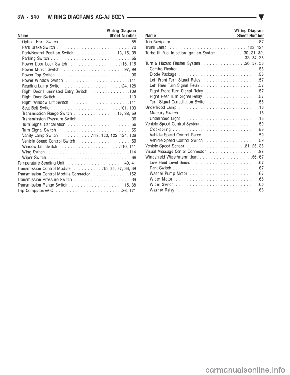
Wiring Diagram
Name Sheet Number
Optical Horn Switch .........................55
Park Brake Switch ...........................70
Park/Neutral Position Switch ...............13, 15, 38
Parking Switch .............................55
Power Door Lock Switch ..................115, 116
Power Mirror Switch ..................... .97, 99
Power Top Switch ...........................96
Power Window Switch ...................... .111
Reading Lamp Switch ................... .124, 126
Right Door Illuminated Entry Switch ..............109
Right Door Switch ......................... .110
Right Window Lift Switch .................... .111
Seat Belt Switch ....................... .101, 103
Transmission Range Switch ................15, 38, 59
Transmission Pressure Switch ...................36
Turn Signal Cancellation .......................56
Turn Signal Switch ..........................55
Vanity Lamp Switch ............118, 120, 122, 124, 126
Vehicle Speed Control Switch ...................59
Window Lift Switch ..................... .110, 111
Wing Switch ............................ .114
Wiper Switch ..............................66
Temperature Sending Unit .................... .40, 41
Transmission Control Module ...........15, 36, 37, 38, 39
Transmission Control Module Connector .............152
Transmission Pressure Switch .....................36
Transmission Range Switch ................... .15, 38
Trip Computer/EVIC ....................... .86, 171Wiring Diagram
Name Sheet Number
Trip Navigator ...............................87
Trunk Lamp ........................... .122, 124
Turbo III Fuel Injection Ignition System .........30, 31, 32,
33, 34, 35
Turn & Hazard Flasher System ...............56, 57, 58
Combo Flasher .............................56
Diode Package .............................56
Left Front Turn Signal Relay ....................57
Left Rear Turn Signal Relay .....................57
Right Front Turn Signal Relay ...................57
Right Rear Turn Signal Relay ....................57
Turn Signal Cancellation Switch ..................56
Underhood Lamp .............................16
Mercury Switch ............................16
Underhood Light ............................16
Vehicle Speed Control System .....................59
Clockspring ...............................59
Vehicle Speed Control Servo ....................59
Vehicle Speed Control Switch ...................59
Vehicle Speed Sensor .................... .21, 25, 35
Visual Message Center Connector ..................88
Windshield Wiper
termittent ...................66, 67
Low Fluid Level Sensor .......................67
Park Switch ...............................67
Washer Pump Motor .........................67
Wiper Motor ..............................66
Wiper Switch ..............................66
Washer Relay .............................66
8W - 540 WIRING DIAGRAMS AG-AJ BODY Ä
Page 1727 of 2438
AY-VEHICLE FRONT BUMPER
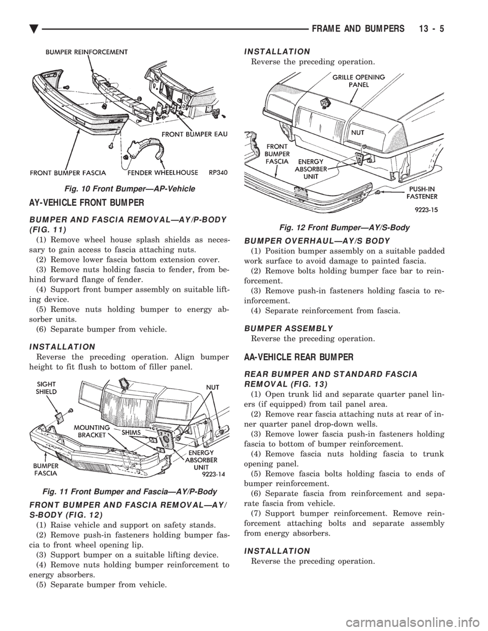
BUMPER AND FASCIA REMOVALÐAY/P-BODY (FIG. 11)
(1) Remove wheel house splash shields as neces-
sary to gain access to fascia attaching nuts. (2) Remove lower fascia bottom extension cover.
(3) Remove nuts holding fascia to fender, from be-
hind forward flange of fender. (4) Support front bumper assembly on suitable lift-
ing device. (5) Remove nuts holding bumper to energy ab-
sorber units. (6) Separate bumper from vehicle.
INSTALLATION
Reverse the preceding operation. Align bumper
height to fit flush to bottom of filler panel.
FRONT BUMPER AND FASCIA REMOVALÐAY/ S-BODY (FIG. 12)
(1) Raise vehicle and support on safety stands.
(2) Remove push-in fasteners holding bumper fas-
cia to front wheel opening lip. (3) Support bumper on a suitable lifting device.
(4) Remove nuts holding bumper reinforcement to
energy absorbers. (5) Separate bumper from vehicle.
INSTALLATION
Reverse the preceding operation.
BUMPER OVERHAULÐAY/S BODY
(1) Position bumper assembly on a suitable padded
work surface to avoid damage to painted fascia. (2) Remove bolts holding bumper face bar to rein-
forcement. (3) Remove push-in fasteners holding fascia to re-
inforcement. (4) Separate reinforcement from fascia.
BUMPER ASSEMBLY
Reverse the preceding operation.
AA-VEHICLE REAR BUMPER
REAR BUMPER AND STANDARD FASCIAREMOVAL (FIG. 13)
(1) Open trunk lid and separate quarter panel lin-
ers (if equipped) from tail panel area. (2) Remove rear fascia attaching nuts at rear of in-
ner quarter panel drop-down wells. (3) Remove lower fascia push-in fasteners holding
fascia to bottom of bumper reinforcement. (4) Remove fascia nuts holding fascia to trunk
opening panel. (5) Remove fascia bolts holding fascia to ends of
bumper reinforcement. (6) Separate fascia from reinforcement and sepa-
rate fascia from vehicle. (7) Support bumper reinforcement. Remove rein-
forcement attaching bolts and separate assembly
from energy absorbers.
INSTALLATION
Reverse the preceding operation.
Fig. 10 Front BumperÐAP-Vehicle
Fig. 11 Front Bumper and FasciaÐAY/P-Body
Fig. 12 Front BumperÐAY/S-Body
Ä FRAME AND BUMPERS 13 - 5
Page 1728 of 2438
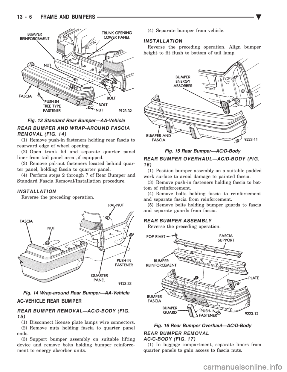
REAR BUMPER AND WRAP-AROUND FASCIA REMOVAL (FIG. 14)
(1) Remove push-in fasteners holding rear fascia to
rearward edge of wheel opening. (2) Open trunk lid and separate quarter panel
liner from tail panel area ,if equipped. (3) Remove pal-nut fasteners located behind quar-
ter panel, holding fascia to quarter panel. (4) Perform steps 2 through 7 of Rear Bumper and
Standard Fascia Removal/Installation procedure.
INSTALLATION
Reverse the preceding operation.
AC-VEHICLE REAR BUMPER
REAR BUMPER REMOVALÐAC/D-BODY (FIG. 15)
(1) Disconnect license plate lamps wire connectors.
(2) Remove nuts holding fascia to quarter panel
ends. (3) Support bumper assembly on suitable lifting
device and remove bolts holding bumper reinforce-
ment to energy absorber units. (4) Separate bumper from vehicle.
INSTALLATION
Reverse the preceding operation. Align bumper
height to fit flush to bottom of tail lamp.
REAR BUMPER OVERHAULÐAC/D-BODY (FIG. 16)
(1) Position bumper assembly on a suitable padded
work surface to avoid damage to painted fascia. (3) Remove push-in fasteners holding fascia to bot-
tom of reinforcement. (4) Remove bolts holding fascia to reinforcement
and separate fascia from reinforcement. (5) Remove bolts holding bumper guards to fascia
and separate guards from fascia.
REAR BUMPER ASSEMBLY
Reverse the preceding operation.
REAR BUMPER REMOVAL AC/C-BODY (FIG. 17)
(1) In luggage compartment, separate liners from
quarter panels to gain access to fascia nuts.
Fig. 13 Standard Rear BumperÐAA-Vehicle
Fig. 14 Wrap-around Rear BumperÐAA-Vehicle
Fig. 15 Rear BumperÐAC/D-Body
Fig. 16 Rear Bumper OverhaulÐAC/D-Body
13 - 6 FRAME AND BUMPERS Ä
Page 1729 of 2438
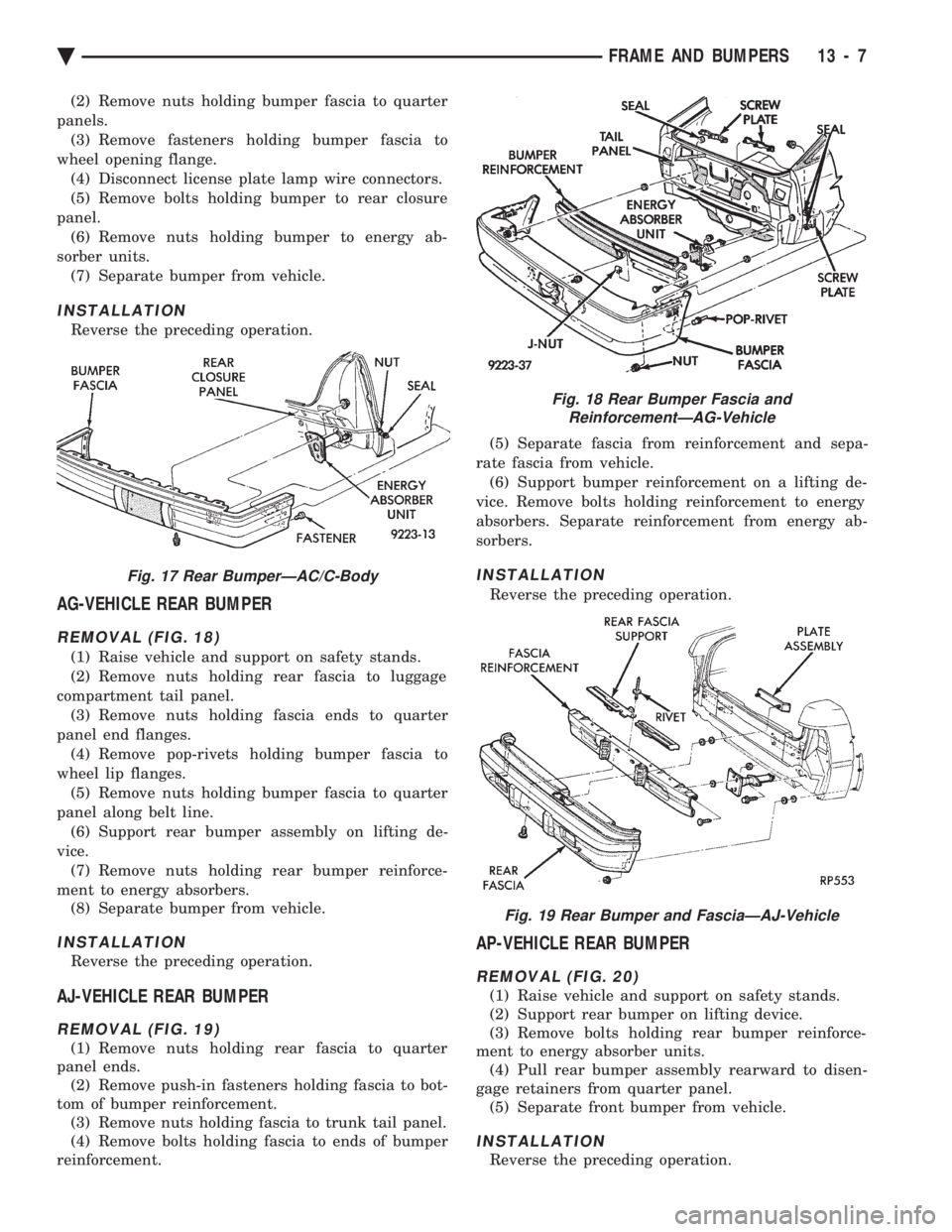
(2) Remove nuts holding bumper fascia to quarter
panels. (3) Remove fasteners holding bumper fascia to
wheel opening flange. (4) Disconnect license plate lamp wire connectors.
(5) Remove bolts holding bumper to rear closure
panel. (6) Remove nuts holding bumper to energy ab-
sorber units. (7) Separate bumper from vehicle.
INSTALLATION
Reverse the preceding operation.
AG-VEHICLE REAR BUMPER
REMOVAL (FIG. 18)
(1) Raise vehicle and support on safety stands.
(2) Remove nuts holding rear fascia to luggage
compartment tail panel. (3) Remove nuts holding fascia ends to quarter
panel end flanges. (4) Remove pop-rivets holding bumper fascia to
wheel lip flanges. (5) Remove nuts holding bumper fascia to quarter
panel along belt line. (6) Support rear bumper assembly on lifting de-
vice. (7) Remove nuts holding rear bumper reinforce-
ment to energy absorbers. (8) Separate bumper from vehicle.
INSTALLATION
Reverse the preceding operation.
AJ-VEHICLE REAR BUMPER
REMOVAL (FIG. 19)
(1) Remove nuts holding rear fascia to quarter
panel ends. (2) Remove push-in fasteners holding fascia to bot-
tom of bumper reinforcement. (3) Remove nuts holding fascia to trunk tail panel.
(4) Remove bolts holding fascia to ends of bumper
reinforcement. (5) Separate fascia from reinforcement and sepa-
rate fascia from vehicle. (6) Support bumper reinforcement on a lifting de-
vice. Remove bolts holding reinforcement to energy
absorbers. Separate reinforcement from energy ab-
sorbers.
INSTALLATION
Reverse the preceding operation.
AP-VEHICLE REAR BUMPER
REMOVAL (FIG. 20)
(1) Raise vehicle and support on safety stands.
(2) Support rear bumper on lifting device.
(3) Remove bolts holding rear bumper reinforce-
ment to energy absorber units. (4) Pull rear bumper assembly rearward to disen-
gage retainers from quarter panel. (5) Separate front bumper from vehicle.
INSTALLATION
Reverse the preceding operation.
Fig. 17 Rear BumperÐAC/C-Body
Fig. 18 Rear Bumper Fascia and ReinforcementÐAG-Vehicle
Fig. 19 Rear Bumper and FasciaÐAJ-Vehicle
Ä FRAME AND BUMPERS 13 - 7
Page 2165 of 2438
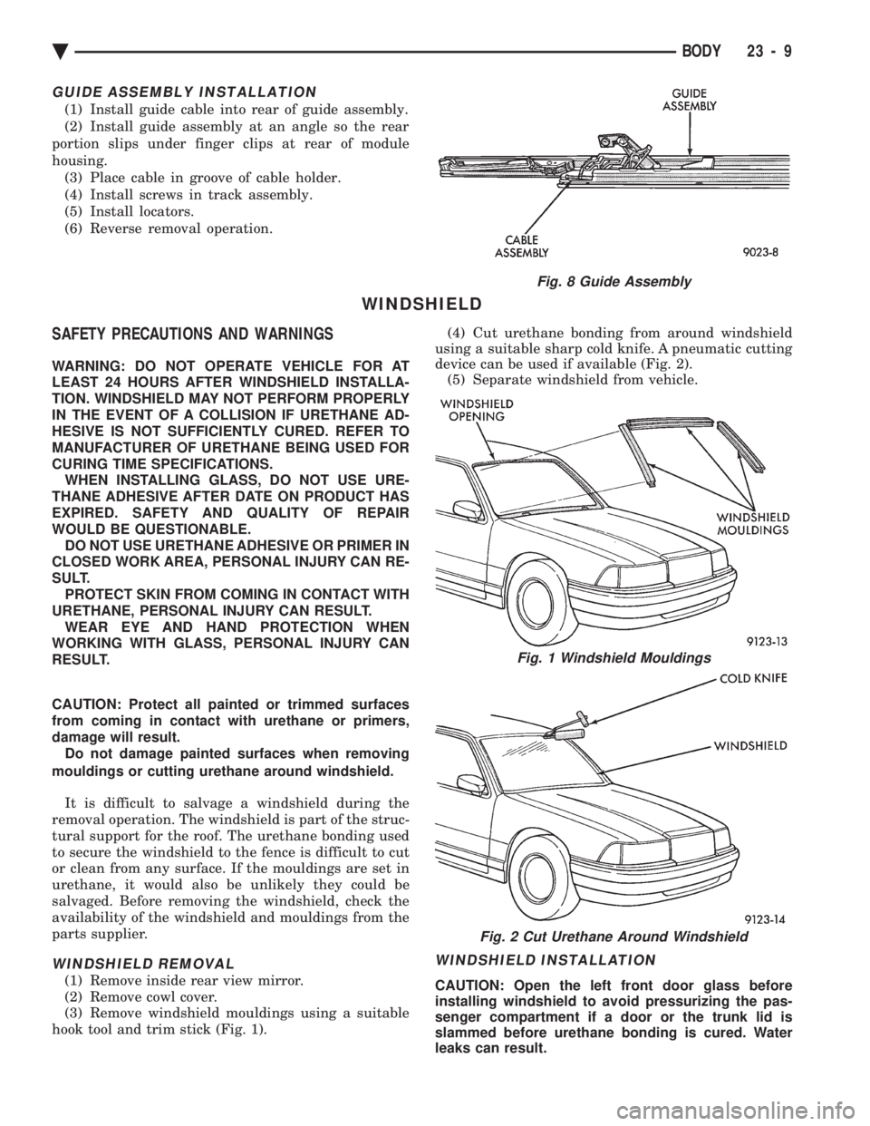
GUIDE ASSEMBLY INSTALLATION
(1) Install guide cable into rear of guide assembly.
(2) Install guide assembly at an angle so the rear
portion slips under finger clips at rear of module
housing. (3) Place cable in groove of cable holder.
(4) Install screws in track assembly.
(5) Install locators.
(6) Reverse removal operation.
WINDSHIELD
SAFETY PRECAUTIONS AND WARNINGS
WARNING: DO NOT OPERATE VEHICLE FOR AT
LEAST 24 HOURS AFTER WINDSHIELD INSTALLA-
TION. WINDSHIELD MAY NOT PERFORM PROPERLY
IN THE EVENT OF A COLLISION IF URETHANE AD-
HESIVE IS NOT SUFFICIENTLY CURED. REFER TO
MANUFACTURER OF URETHANE BEING USED FOR
CURING TIME SPECIFICATIONS. WHEN INSTALLING GLASS, DO NOT USE URE-
THANE ADHESIVE AFTER DATE ON PRODUCT HAS
EXPIRED. SAFETY AND QUALITY OF REPAIR
WOULD BE QUESTIONABLE. DO NOT USE URETHANE ADHESIVE OR PRIMER IN
CLOSED WORK AREA, PERSONAL INJURY CAN RE-
SULT. PROTECT SKIN FROM COMING IN CONTACT WITH
URETHANE, PERSONAL INJURY CAN RESULT. WEAR EYE AND HAND PROTECTION WHEN
WORKING WITH GLASS, PERSONAL INJURY CAN
RESULT.
CAUTION: Protect all painted or trimmed surfaces
from coming in contact with urethane or primers,
damage will result. Do not damage painted surfaces when removing
mouldings or cutting urethane around windshield.
It is difficult to salvage a windshield during the
removal operation. The windshield is part of the struc-
tural support for the roof. The urethane bonding used
to secure the windshield to the fence is difficult to cut
or clean from any surface. If the mouldings are set in
urethane, it would also be unlikely they could be
salvaged. Before removing the windshield, check the
availability of the windshield and mouldings from the
parts supplier.
WINDSHIELD REMOVAL
(1) Remove inside rear view mirror.
(2) Remove cowl cover.
(3) Remove windshield mouldings using a suitable
hook tool and trim stick (Fig. 1). (4) Cut urethane bonding from around windshield
using a suitable sharp cold knife. A pneumatic cutting
device can be used if available (Fig. 2). (5) Separate windshield from vehicle.
WINDSHIELD INSTALLATION
CAUTION: Open the left front door glass before
installing windshield to avoid pressurizing the pas-
senger compartment if a door or the trunk lid is
slammed before urethane bonding is cured. Water
leaks can result.
Fig. 8 Guide Assembly
Fig. 1 Windshield Mouldings
Fig. 2 Cut Urethane Around Windshield
Ä BODY 23 - 9
Page 2167 of 2438
AA-VEHICLE BODY COMPONENT SERVICE INDEX
page page
A-Pillar and Roof Rail Mouldings ............. 25
B-Pillar Trim Panel ....................... 25
Body Side Moulding and Applique ............ 24
Cowl Cover ............................. 13
Cowl Panel Trim and Scuff Plates ............ 25
Door Opening Weatherstrips ................ 24
Floor Carpet ............................ 30
Front Center Console ..................... 29
Front Door and Hinge ..................... 15
Front Door Belt Moulding and Weatherstrip ..... 17
Front Door Glass ........................ 17
Front Door Glass Channel and Run Weatherstrip . 18
Front Door Glass Run Lower Channel ......... 18
Front Door Latch ......................... 16
Front Door Side View Mirror ................ 17
Front Door Silencer and Water Shield ......... 15
Front Door Trim Panel .................... 14
Front Door Window Regulator/Manual ......... 18
Front Door Window Regulator/Power .......... 19
Front End Splash Shields .................. 13
Front Fender ............................ 14
Front Power Door Lock Actuator ............. 19
Front Seat Belts ......................... 27
Front Seats ............................. 28
Fuel Fill Door ........................... 36
Grille .................................. 11
Head Lining ............................. 30
Hood and Hinges ........................ 11
Hood Latch and Release Cable .............. 12
Outside Front Door Latch Release Handle ..... 16
Outside Rear Door Latch Release Handle ...... 21 Overhead Console
........................ 30
Quarter Extension Trim Panel ............... 27
Quarter Trim Panel ....................... 27
Rear Deck Filler Panel .................... 31
Rear Door and Hinge ..................... 20
Rear Door Belt Moulding and Weatherstrip ..... 22
Rear Door Glass ......................... 22
Rear Door Glass Run Weatherstrip ........... 22
Rear Door Glass Stationary Glass Module ..... 23
Rear Door Latch ......................... 21
Rear Door Silencer and Water Shield ......... 20
Rear Door Trim Panel ..................... 20
Rear Door Window Regulator/Manual ......... 23
Rear Door Window Regulator/Power .......... 23
Rear Power Door Lock Actuator ............. 22
Rear Seat Belts .......................... 28
Rear Seats ............................. 28
Rear Shelf Trim Panel ..................... 27
Rear Window Glass ...................... 32
Sun Roof Air Deflector .................... 31
Sun Roof Drain Tubes .................... 31
Sun Roof Weatherstrip .................... 31
Trunk Lid .............................. 33
Trunk Lid Hinge ......................... 34
Trunk Lid Latch .......................... 34
Trunk Lid Lock .......................... 34
Trunk Lid Luggage Rack ................... 35
Trunk Lid Torsion Bar ..................... 34
Trunk Lining ............................ 35
Trunk Opening Weatherstrip ................ 35
Vinyl Roof Bonnet ........................ 31
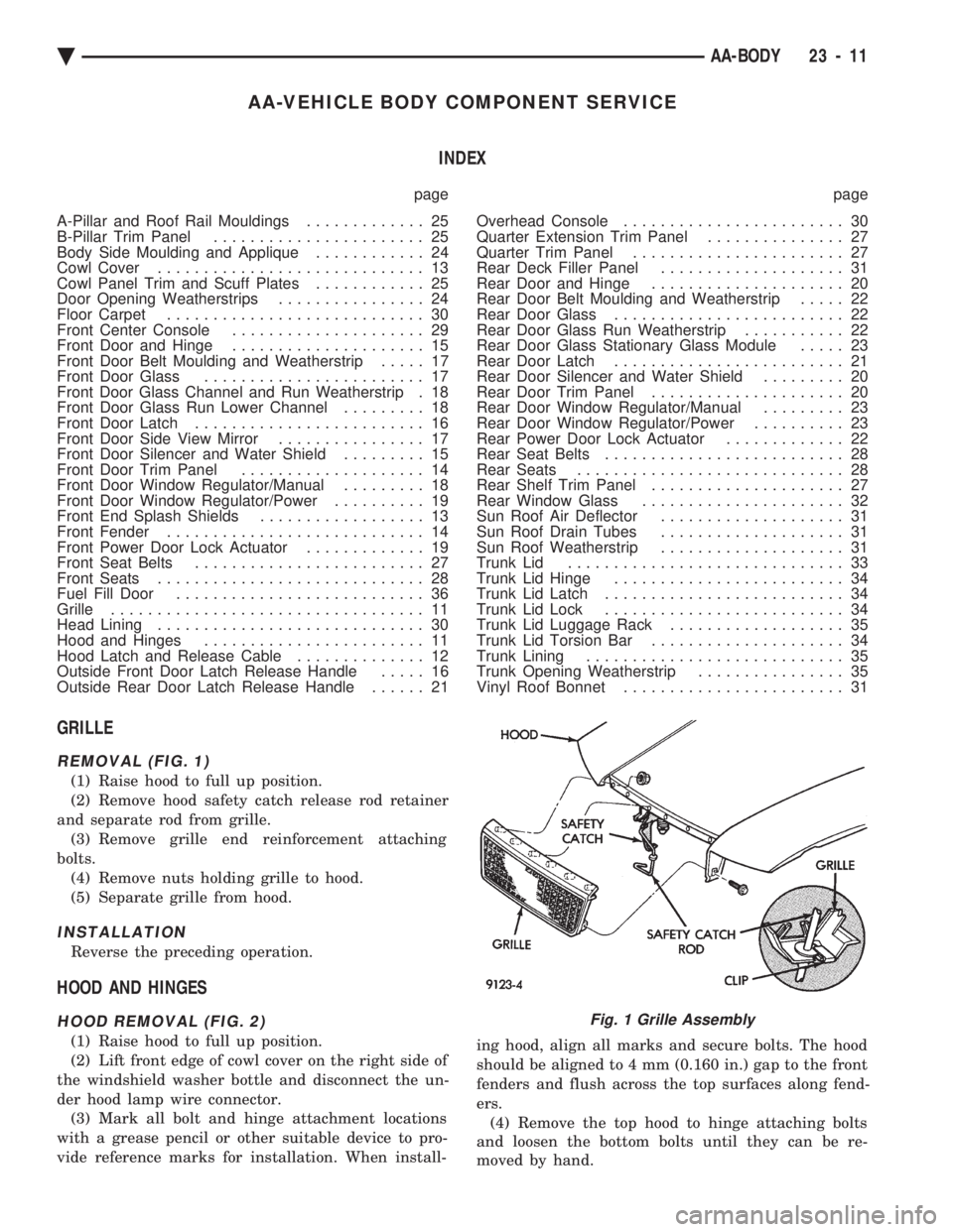
GRILLE
REMOVAL (FIG. 1)
(1) Raise hood to full up position.
(2) Remove hood safety catch release rod retainer
and separate rod from grille. (3) Remove grille end reinforcement attaching
bolts. (4) Remove nuts holding grille to hood.
(5) Separate grille from hood.
INSTALLATION
Reverse the preceding operation.
HOOD AND HINGES
HOOD REMOVAL (FIG. 2)
(1) Raise hood to full up position.
(2) Lift front edge of cowl cover on the right side of
the windshield washer bottle and disconnect the un-
der hood lamp wire connector. (3) Mark all bolt and hinge attachment locations
with a grease pencil or other suitable device to pro-
vide reference marks for installation. When install- ing hood, align all marks and secure bolts. The hood
should be aligned to 4 mm (0.160 in.) gap to the front
fenders and flush across the top surfaces along fend-
ers. (4) Remove the top hood to hinge attaching bolts
and loosen the bottom bolts until they can be re-
moved by hand.
Fig. 1 Grille Assembly
Ä AA-BODY 23 - 11
Page 2185 of 2438
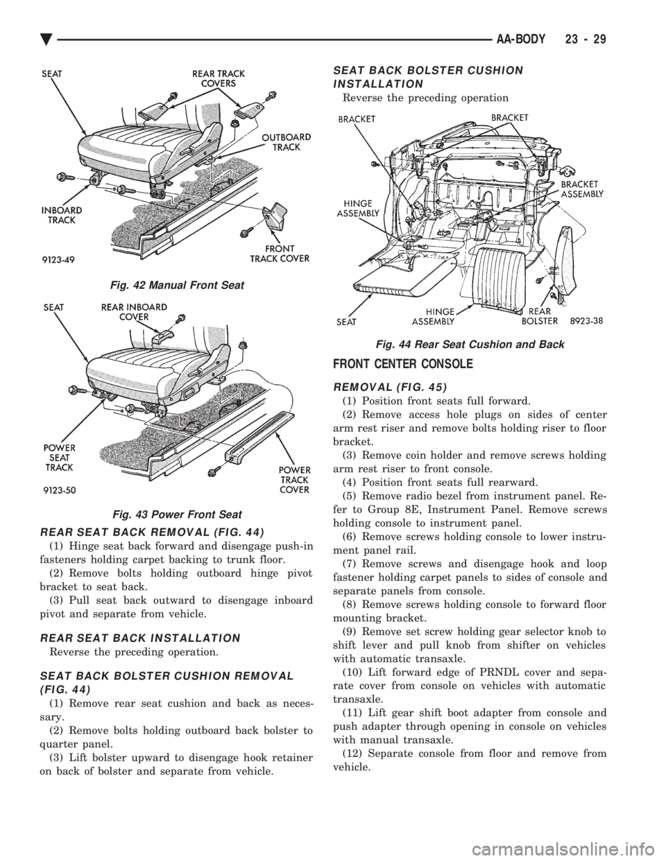
REAR SEAT BACK REMOVAL (FIG. 44)
(1) Hinge seat back forward and disengage push-in
fasteners holding carpet backing to trunk floor. (2) Remove bolts holding outboard hinge pivot
bracket to seat back. (3) Pull seat back outward to disengage inboard
pivot and separate from vehicle.
REAR SEAT BACK INSTALLATION
Reverse the preceding operation.
SEAT BACK BOLSTER CUSHION REMOVAL (FIG. 44)
(1) Remove rear seat cushion and back as neces-
sary. (2) Remove bolts holding outboard back bolster to
quarter panel. (3) Lift bolster upward to disengage hook retainer
on back of bolster and separate from vehicle.
SEAT BACK BOLSTER CUSHION INSTALLATION
Reverse the preceding operation
FRONT CENTER CONSOLE
REMOVAL (FIG. 45)
(1) Position front seats full forward.
(2) Remove access hole plugs on sides of center
arm rest riser and remove bolts holding riser to floor
bracket. (3) Remove coin holder and remove screws holding
arm rest riser to front console. (4) Position front seats full rearward.
(5) Remove radio bezel from instrument panel. Re-
fer to Group 8E, Instrument Panel. Remove screws
holding console to instrument panel. (6) Remove screws holding console to lower instru-
ment panel rail. (7) Remove screws and disengage hook and loop
fastener holding carpet panels to sides of console and
separate panels from console. (8) Remove screws holding console to forward floor
mounting bracket. (9) Remove set screw holding gear selector knob to
shift lever and pull knob from shifter on vehicles
with automatic transaxle. (10) Lift forward edge of PRNDL cover and sepa-
rate cover from console on vehicles with automatic
transaxle. (11) Lift gear shift boot adapter from console and
push adapter through opening in console on vehicles
with manual transaxle. (12) Separate console from floor and remove from
vehicle.
Fig. 42 Manual Front Seat
Fig. 43 Power Front Seat
Fig. 44 Rear Seat Cushion and Back
Ä AA-BODY 23 - 29