1993 CHEVROLET PLYMOUTH ACCLAIM headlamp
[x] Cancel search: headlampPage 652 of 2438
EXTERIOR LAMPSÐAC BODY INDEX
page page
Aero Headlamp Bulb ...................... 10
Aero Headlamp Housing ................... 11
Aero HeadlampsÐAC/D-Body ............... 10
Center High Mounted Stop Lamp (CHMSL) ..... 13
Center High-Mounted Stop Lamp (CHMSL) Bulb . 13
Cornering Lamp Assembly .................. 12
Cornering Lamp Bulb ..................... 12
Front Side Marker BulbÐAC/C-Body .......... 12
Front Side Marker LampÐAC/C-Body ......... 12
Headlamp Diagnosis ...................... 10 Headlamp Sealed BeamÐAC/C Body
......... 10
License Plate Lamp/Bulb ................... 13
Park/Turn Signal Lamp or BulbÐAC/C-Body .... 11
Park/Turn Signal Lamp or BulbÐAC/D-Body .... 11
Rear Side Marker Lamp BulbÐAC/C-Body ..... 13
Rear Side Marker LampÐAC/C-Body ......... 13
Tail, Stop, Turn Signal, Back-Up and Side Marker LampÐAC/D-Body ...................... 12
Tail, Stop, Turn Signal, Back-Up LampÐAC/C or AY/S-Body ............................ 12
HEADLAMP DIAGNOSIS
Refer to the Headlamp Diagnosis at the beginning of
this Group. Refer to Wiring Diagrams Manual for
circuit and component locations.
HEADLAMP SEALED BEAMÐAC/C BODY
REMOVAL
(1) Turn the headlight switch ON.
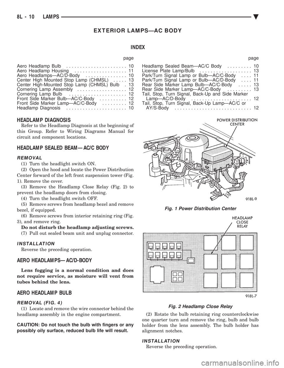
(2) Open the hood and locate the Power Distribution
Center forward of the left front suspension tower (Fig.
1). Remove the cover. (3) Remove the Headlamp Close Relay (Fig. 2) to
prevent the headlamp doors from closing. (4) Turn the headlight switch OFF.
(5) Remove screws from headlamp bezel and remove
bezel, if equipped. (6) Remove screws from interior retaining ring (Fig.
3), and remove ring. Do not disturb the headlamp adjusting screws.
(7) Pull out sealed beam unit and unplug connector.
INSTALLATION
Reverse the preceding operation.
AERO HEADLAMPSÐAC/D-BODY
Lens fogging is a normal condition and does
not require service, as moisture will vent from
tubes behind the lens.
AERO HEADLAMP BULB
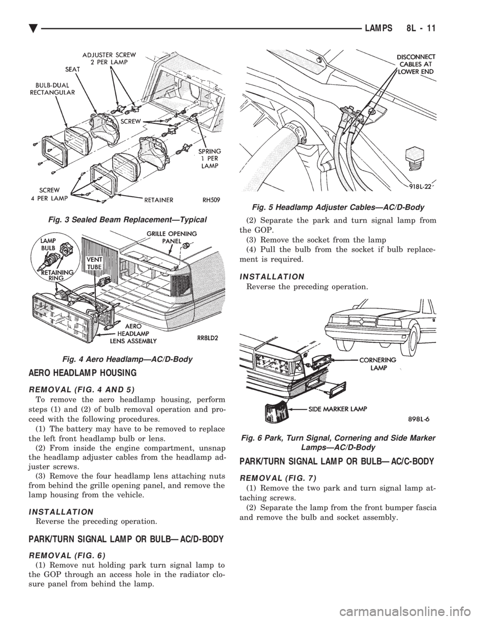
REMOVAL (FIG. 4)
(1) Locate and remove the wire connector behind the
headlamp assembly in the engine compartment.
CAUTION: Do not touch the bulb with fingers or any
possibly oily surface, reduced bulb life will result. (2) Rotate the bulb retaining ring counterclockwise
one quarter turn and remove the ring, bulb and bulb
holder from the lens assembly. The bulb holder has
alignment notches.
INSTALLATION
Reverse the preceding operation.
Fig. 1 Power Distribution Center
Fig. 2 Headlamp Close Relay
8L - 10 LAMPS Ä
Page 653 of 2438
AERO HEADLAMP HOUSING
REMOVAL (FIG. 4 AND 5)
To remove the aero headlamp housing, perform
steps (1) and (2) of bulb removal operation and pro-
ceed with the following procedures. (1) The battery may have to be removed to replace
the left front headlamp bulb or lens. (2) From inside the engine compartment, unsnap
the headlamp adjuster cables from the headlamp ad-
juster screws. (3) Remove the four headlamp lens attaching nuts
from behind the grille opening panel, and remove the
lamp housing from the vehicle.
INSTALLATION
Reverse the preceding operation.
PARK/TURN SIGNAL LAMP OR BULBÐAC/D-BODY
REMOVAL (FIG. 6)
(1) Remove nut holding park turn signal lamp to
the GOP through an access hole in the radiator clo-
sure panel from behind the lamp. (2) Separate the park and turn signal lamp from
the GOP. (3) Remove the socket from the lamp
(4) Pull the bulb from the socket if bulb replace-
ment is required.
INSTALLATION
Reverse the preceding operation.
PARK/TURN SIGNAL LAMP OR BULBÐAC/C-BODY
REMOVAL (FIG. 7)
(1) Remove the two park and turn signal lamp at-
taching screws. (2) Separate the lamp from the front bumper fascia
and remove the bulb and socket assembly.
Fig. 3 Sealed Beam ReplacementÐTypical
Fig. 4 Aero HeadlampÐAC/D-Body
Fig. 5 Headlamp Adjuster CablesÐAC/D-Body
Fig. 6 Park, Turn Signal, Cornering and Side Marker LampsÐAC/D-Body
Ä LAMPS 8L - 11
Page 656 of 2438
EXTERIOR LAMPSÐAG BODY INDEX
page page
Back-Up Lamps .......................... 15
Center High Mounted Stop Lamp Bulb ........ 15
Fog Lamp or Bulb ........................ 14
Headlamp Diagnosis ...................... 14
Headlamp Housing and Bulb ................ 14 License Plate Lamp or Bulb
................ 15
Park and Turn Signal Lamp or Bulb .......... 14
Tail, Stop, Turn Signal, Side Marker, Back-Up Lamp ................................ 15
HEADLAMP DIAGNOSIS
For headlamp diagnosis, refer to the Headlamp Di-
agnosis at the beginning of this Group. Refer to Wir-
ing Diagrams manual for circuit and component
locations.
HEADLAMP HOUSING AND BULB
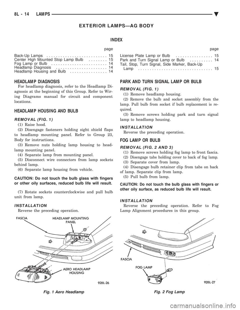
REMOVAL (FIG. 1)
(1) Raise hood.
(2) Disengage fasteners holding sight shield flaps
to headlamp mounting panel. Refer to Group 23,
Body for instructions. (3) Remove nuts holding lamp housing to head-
lamp mounting panel. (4) Separate lamp from mounting panel.
(5) Disconnect wire connectors from lamp sockets
behind lamp. (6) Separate lamp housing from vehicle.
CAUTION: Do not touch the bulb glass with fingers
or other oily surfaces, reduced bulb life will result. (7) Rotate sockets counterclockwise and pull bulb
unit from lamp.
INSTALLATION
Reverse the preceding operation.
PARK AND TURN SIGNAL LAMP OR BULB
REMOVAL (FIG. 1)
(1) Remove headlamp housing.
(2) Remove the bulb and socket assembly from the
lamp. Pull bulb from socket if bulb replacement is re-
quired.
(3) Remove screws holding park and turn signal
lamp to headlamp housing.
INSTALLATION
Reverse the preceding operation.
FOG LAMP OR BULB
REMOVAL (FIG. 2 AND 3)
(1) Remove screws holding fog lamp to front fascia.
(2) Disengage tabs holding cover to back of fog lamp.
(3) Separate cover from lamp.
(4) Disengage bulb retainer clip from tabs on back
of lamp. Separate clip from lamp. (5) Pull bulb from lamp.
CAUTION: Do not touch the bulb glass with fingers or
other oily surface, as reduced bulb life will result.
INSTALLATION
Reverse the preceding operation. Refer to Fog
Lamp Alignment procedures in this group.
Fig. 1 Aero HeadlampFig. 2 Fog Lamp
8L - 14 LAMPS Ä
Page 658 of 2438
EXTERIOR LAMPSÐAJ BODY INDEX
page page
Back-Up Lamp .......................... 17
Back-Up Lamp Bulb ...................... 17
Center High Mounted Stop Lamp (CHMSL) Bulb . 18
Center High-Mounted Stop Lamp Assembly (CHMSL) ............................. 18
Cornering Lamp or Bulb ................... 16
Front Side Marker Lamp ................... 16
Front Side Marker Lamp Bulb ............... 16
Headlamp Module and Bulb ................ 16 Headlamps
............................. 16
License Plate Lamp or Bulb ................ 17
Park and Turn Signal Lamp or Bulb .......... 16
Rear Side Marker Lamp ................... 17
Rear Side Marker Lamp Bulb ............... 17
Tail, Stop, Turn Signal Bulb or Lamp ......... 17
Trunk Lid Tail Lamp ...................... 17
Trunk Lid Tail Lamp Bulb .................. 17
HEADLAMPS
HEADLAMP MODULE AND BULB
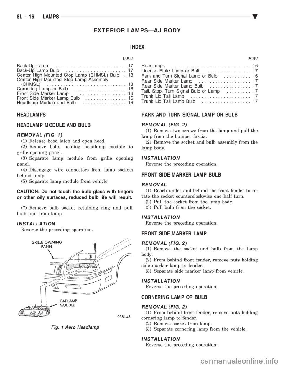
REMOVAL (FIG. 1)
(1) Release hood latch and open hood.
(2) Remove bolts holding headlamp module to
grille opening panel. (3) Separate lamp module from grille opening
panel. (4) Disengage wire connectors from lamp sockets
behind lamp. (5) Separate lamp module from vehicle.
CAUTION: Do not touch the bulb glass with fingers
or other oily surfaces, reduced bulb life will result. (7) Remove bulb socket retaining ring and pull
bulb unit from lamp.
INSTALLATION
Reverse the preceding operation.
PARK AND TURN SIGNAL LAMP OR BULB
REMOVAL (FIG. 2)
(1) Remove two screws from the lamp and pull the
lamp from the bumper fascia. (2) Remove the socket and bulb assembly from the
lamp body.
INSTALLATION
Reverse the preceding operation.
FRONT SIDE MARKER LAMP BULB
REMOVAL
(1) Reach under and behind the front fender to ro-
tate the socket counterclockwise one half turn. (2) Pull the socket from the lamp body.
(3) Pull bulb from the socket.
INSTALLATION
Reverse the preceding operation.
FRONT SIDE MARKER LAMP
REMOVAL (FIG. 2)
(1) Remove the socket and bulb from the lamp
body. (2) From behind front fender, remove nuts holding
side marker lamp to fender. (3) Separate side marker lamp from vehicle.
INSTALLATION
Reverse the preceding operation.
CORNERING LAMP OR BULB
REMOVAL (FIG. 2)
(1) From behind front fender, remove nuts holding
cornering lamp to fender. (2) Remove socket from lamp.
(3) Separate cornering lamp from the vehicle.
INSTALLATION
Reverse the preceding operation.
Fig. 1 Aero Headlamp
8L - 16 LAMPS Ä
Page 661 of 2438
EXTERIOR LAMPSÐAP BODY INDEX
page page
Center High Mounted Stop Lamp (CHMSL)Ð AP/24-44-Body ......................... 21
Center High Mounted Stop Lamp BulbÐ AP/24-44-Body ......................... 21
Fog Lamp Bulb .......................... 21
Fog Lamps ............................. 21
Front Side Marker Lamp or Bulb ............. 20
Headlamp Bulb .......................... 19 Headlamp Diagnosis
...................... 19
Headlamp Housing ....................... 19
License Plate Lamp or Bulb ................ 20
Park and Turn Signal Lamp or Bulb .......... 20
Tail, Stop, Turn Signal, Back-Up and Side Marker Lamp ................................ 20
Tail, Stop, Turn Signal, Back-Up and Side Marker Lamp Bulbs ........................... 20
HEADLAMP DIAGNOSIS
For headlamp diagnosis, refer to the headlamp di-
agnosis chart at the beginning of this group. Refer to
Wiring Diagrams manual for circuit and component
locations.
HEADLAMP BULB
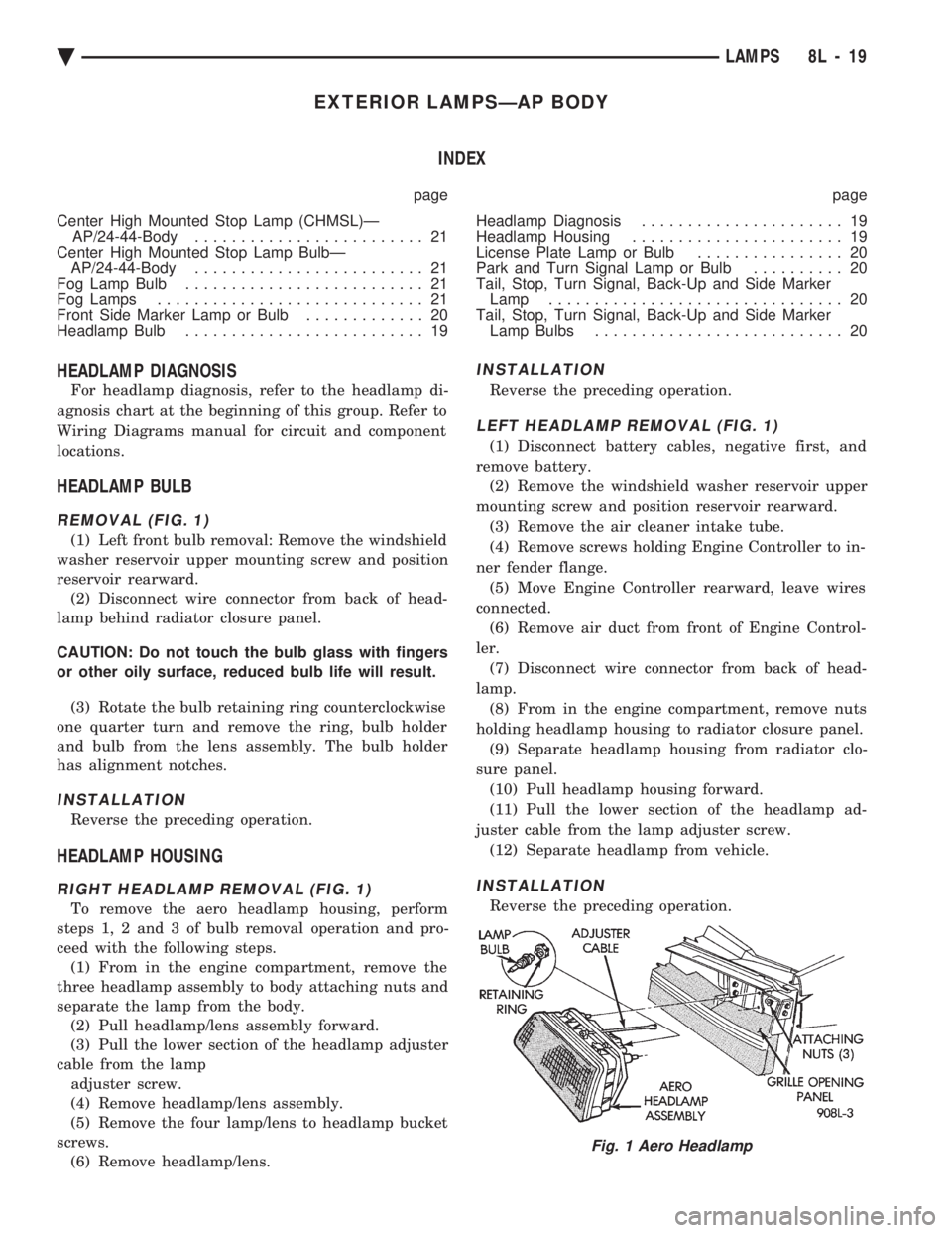
REMOVAL (FIG. 1)
(1) Left front bulb removal: Remove the windshield
washer reservoir upper mounting screw and position
reservoir rearward. (2) Disconnect wire connector from back of head-
lamp behind radiator closure panel.
CAUTION: Do not touch the bulb glass with fingers
or other oily surface, reduced bulb life will result.
(3) Rotate the bulb retaining ring counterclockwise
one quarter turn and remove the ring, bulb holder
and bulb from the lens assembly. The bulb holder
has alignment notches.
INSTALLATION
Reverse the preceding operation.
HEADLAMP HOUSING
RIGHT HEADLAMP REMOVAL (FIG. 1)
To remove the aero headlamp housing, perform
steps 1, 2 and 3 of bulb removal operation and pro-
ceed with the following steps. (1) From in the engine compartment, remove the
three headlamp assembly to body attaching nuts and
separate the lamp from the body. (2) Pull headlamp/lens assembly forward.
(3) Pull the lower section of the headlamp adjuster
cable from the lamp adjuster screw.
(4) Remove headlamp/lens assembly.
(5) Remove the four lamp/lens to headlamp bucket
screws. (6) Remove headlamp/lens.
INSTALLATION
Reverse the preceding operation.
LEFT HEADLAMP REMOVAL (FIG. 1)
(1) Disconnect battery cables, negative first, and
remove battery. (2) Remove the windshield washer reservoir upper
mounting screw and position reservoir rearward. (3) Remove the air cleaner intake tube.
(4) Remove screws holding Engine Controller to in-
ner fender flange. (5) Move Engine Controller rearward, leave wires
connected. (6) Remove air duct from front of Engine Control-
ler. (7) Disconnect wire connector from back of head-
lamp. (8) From in the engine compartment, remove nuts
holding headlamp housing to radiator closure panel. (9) Separate headlamp housing from radiator clo-
sure panel. (10) Pull headlamp housing forward.
(11) Pull the lower section of the headlamp ad-
juster cable from the lamp adjuster screw. (12) Separate headlamp from vehicle.
INSTALLATION
Reverse the preceding operation.
Fig. 1 Aero Headlamp
Ä LAMPS 8L - 19
Page 664 of 2438
EXTERIOR LAMPSÐAY-BODY INDEX
page page
Center High Mounted Stop Lamp ............ 24
Center High Mounted Stop Lamp Bulb (CHMSL) . 24
Cornering Lamp or BulbÐAY/C-P-Body ........ 24
Front Side Marker BulbÐAY/C-P-Body ........ 23
Front Side Marker LampÐAY/C-P-Body ....... 23
General Information ....................... 22
Headlamp Diagnosis ...................... 22 Headlamps
............................. 22
License Plate Lamp or BulbÐAY/C-P-Body ..... 24
Park, Turn Signal Lamp or BulbÐAY/C-P-Body . . 22
Sealed Beam ........................... 22
Tail, Stop, Turn Signal, Side Marker and Back-Up Lamp or BulbÐAY/C-P-Body .............. 24
GENERAL INFORMATION
To service exterior lamps on AY/C-S-Body, refer to
procedures covered in Exterior LampsÐAC-Body sec-
tion. AC/C-S-Body uses the same lamps as AY/C-S-
Body.
HEADLAMPS
Conventional and halogen sealed beams are inter-
changeable, It is not recommended that they be
mixed. The lens, filament and reflector of sealed
beams are molded into one unit.
HEADLAMP DIAGNOSIS
For headlamp diagnosis, refer to the headlamp di-
agnosis chart at the beginning of this Group. Refer to
Wiring Diagrams manual for circuit and component
locations.
SEALED BEAM
REMOVAL
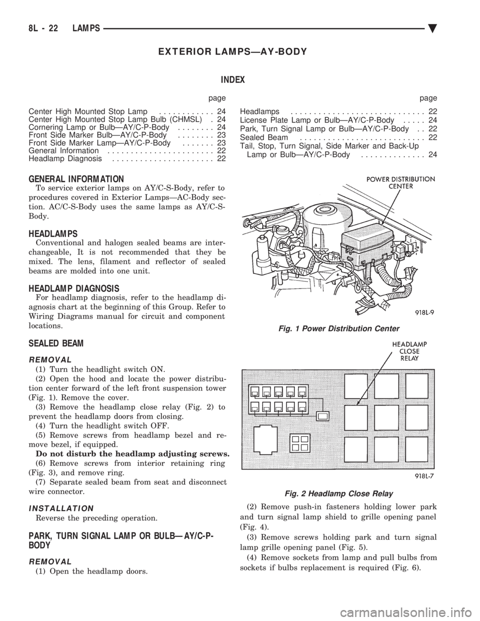
(1) Turn the headlight switch ON.
(2) Open the hood and locate the power distribu-
tion center forward of the left front suspension tower
(Fig. 1). Remove the cover. (3) Remove the headlamp close relay (Fig. 2) to
prevent the headlamp doors from closing. (4) Turn the headlight switch OFF.
(5) Remove screws from headlamp bezel and re-
move bezel, if equipped. Do not disturb the headlamp adjusting screws.
(6) Remove screws from interior retaining ring
(Fig. 3), and remove ring. (7) Separate sealed beam from seat and disconnect
wire connector.
INSTALLATION
Reverse the preceding operation.
PARK, TURN SIGNAL LAMP OR BULBÐAY/C-P-
BODY
REMOVAL
(1) Open the headlamp doors. (2) Remove push-in fasteners holding lower park
and turn signal lamp shield to grille opening panel
(Fig. 4). (3) Remove screws holding park and turn signal
lamp grille opening panel (Fig. 5). (4) Remove sockets from lamp and pull bulbs from
sockets if bulbs replacement is required (Fig. 6).
Fig. 1 Power Distribution Center
Fig. 2 Headlamp Close Relay
8L - 22 LAMPS Ä
Page 667 of 2438
EXTERIOR LAMP SYSTEMS INDEX
page page
Daytime Running LampÐCanada Only ........ 25
Headlamp Time Delay System .............. 26
Lamp Outage ModuleÐAA-Body ............. 25 Lamp Outage ModuleÐAll Except AA-Body
..... 25
Lamp Outage System ..................... 25
Removal (Fig. 4) ......................... 25
LAMP OUTAGE SYSTEM
Diagnostics and component relationships for AC,
AG, AJ or AY-Bodies can be found in the Body Di-
agnostic Procedures Manual, Electronic Vehicle In-
formation Center (EVIC) section. For circuit and component locations on AA-body,
refer to the Wiring Diagrams Manual.
LAMP OUTAGE MODULEÐALL EXCEPT AA-BODY
REMOVAL
(1) Remove battery negative cable.
(2) Remove the glove box assembly. Refer to Group
8E, Instrument Panel. (3) Disconnect the wire connector from the lamp
outage module. (4) Remove lamp outage module attaching screw
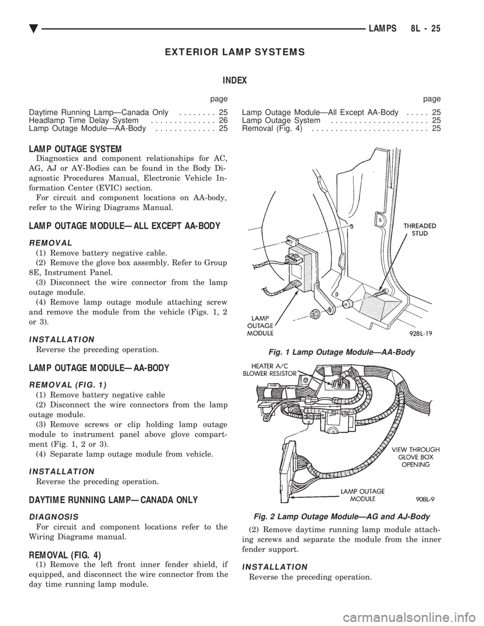
and remove the module from the vehicle (Figs. 1, 2
or 3).
INSTALLATION
Reverse the preceding operation.
LAMP OUTAGE MODULEÐAA-BODY
REMOVAL (FIG. 1)
(1) Remove battery negative cable
(2) Disconnect the wire connectors from the lamp
outage module. (3) Remove screws or clip holding lamp outage
module to instrument panel above glove compart-
ment (Fig. 1, 2 or 3). (4) Separate lamp outage module from vehicle.
INSTALLATION
Reverse the preceding operation.
DAYTIME RUNNING LAMPÐCANADA ONLY
DIAGNOSIS
For circuit and component locations refer to the
Wiring Diagrams manual.
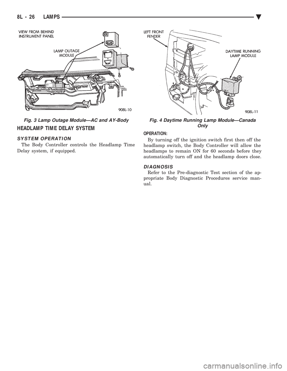
REMOVAL (FIG. 4)
(1) Remove the left front inner fender shield, if
equipped, and disconnect the wire connector from the
day time running lamp module. (2) Remove daytime running lamp module attach-
ing screws and separate the module from the inner
fender support.INSTALLATION
Reverse the preceding operation.
Fig. 1 Lamp Outage ModuleÐAA-Body
Fig. 2 Lamp Outage ModuleÐAG and AJ-Body
Ä LAMPS 8L - 25
Page 668 of 2438
HEADLAMP TIME DELAY SYSTEM
SYSTEM OPERATION
The Body Controller controls the Headlamp Time
Delay system, if equipped. OPERATION:
By turning off the ignition switch first then off the
headlamp switch, the Body Controller will allow the
headlamps to remain ON for 60 seconds before they
automatically turn off and the headlamp doors close.
DIAGNOSIS
Refer to the Pre-diagnostic Test section of the ap-
propriate Body Diagnostic Procedures service man-
ual.
Fig. 3 Lamp Outage ModuleÐAC and AY-BodyFig. 4 Daytime Running Lamp ModuleÐCanada Only
8L - 26 LAMPS Ä