1993 CHEVROLET PLYMOUTH ACCLAIM seats
[x] Cancel search: seatsPage 1064 of 2438
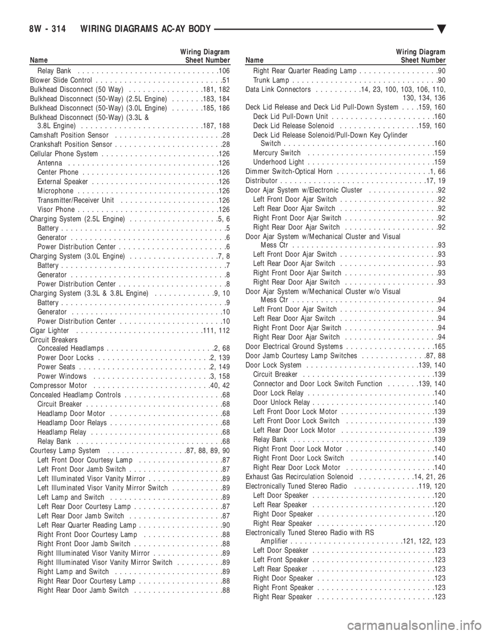
Wiring Diagram
Name Sheet Number
Relay Bank ............................. .106
Blower Slide Control ...........................51
Bulkhead Disconnect (50 Way) ................181, 182
Bulkhead Disconnect (50-Way) (2.5L Engine) .......183, 184
Bulkhead Disconnect (50-Way) (3.0L Engine) .......185, 186
Bulkhead Disconnect (50-Way) (3.3L & 3.8L Engine) ......................... .187, 188
Camshaft Position Sensor .......................28
Crankshaft Position Sensor .......................28
Cellular Phone System ........................ .126
Antenna ............................... .126
Center Phone ............................ .126
External Speaker .......................... .126
Microphone ............................. .126
Transmitter/Receiver Unit .................... .126
Visor Phone ............................. .126
Charging System (2.5L Engine) ...................5,6
Battery ...................................5
Generator .................................6
Power Distribution Center .......................6
Charging System (3.0L Engine) ...................7,8
Battery ...................................7
Generator .................................8
Power Distribution Center .......................8
Charging System (3.3L & 3.8L Engine) .............9,10
Battery ...................................9
Generator ................................10
Power Distribution Center ......................10
Cigar Lighter .......................... .111, 112
Circuit Breakers Concealed Headlamps .......................2,68
Power Door Locks ........................2,139
Power Seats ............................2,149
Power Windows .........................3,158
Compressor Motor ........................ .40, 42
Concealed Headlamp Controls .....................68
Circuit Breaker .............................68
Headlamp Door Motor ........................68
Headlamp Door Relays ........................68
Headlamp Relay ............................68
Relay Bank ...............................68
Courtesy Lamp System .................87, 88, 89, 90
Left Front Door Courtesy Lamp ..................87
Left Front Door Jamb Switch ....................87
Left Illuminated Visor Vanity Mirror ................89
Left Illuminated Visor Vanity Mirror Switch ...........89
Left Lamp and Switch ........................89
Left Rear Door Courtesy Lamp ...................87
Left Rear Door Jamb Switch ....................87
Left Rear Quarter Reading Lamp ..................90
Right Front Door Courtesy Lamp .................88
Right Front Door Jamb Switch ...................88
Right Illuminated Visor Vanity Mirror ...............89
Right Illuminated Visor Vanity Mirror Switch ..........89
Right Lamp and Switch .......................89
Right Rear Door Courtesy Lamp ..................88
Right Rear Door Jamb Switch ...................88Wiring Diagram
Name Sheet Number
Right Rear Quarter Reading Lamp .................90
Trunk Lamp ...............................90
Data Link Connectors ..........14, 23, 100, 103, 106, 110,
130, 134, 136
Deck Lid Release and Deck Lid Pull-Down System . . . .159, 160
Deck Lid Pull-Down Unit ..................... .160
Deck Lid Release Solenoid .................159, 160
Deck Lid Release Solenoid/Pull-Down Key Cylinder Switch ............................... .160
Mercury Switch .......................... .159
Underhood Light .......................... .159
Dimmer Switch-Optical Horn ....................1,66
Distributor .............................. .17, 19
Door Ajar System w/Electronic Cluster ...............92
Left Front Door Ajar Switch .....................92
Left Rear Door Ajar Switch .....................92
Right Front Door Ajar Switch ....................92
Right Rear Door Ajar Switch ....................92
Door Ajar System w/Mechanical Cluster and Visual Mess Ctr ...............................93
Left Front Door Ajar Switch .....................93
Left Rear Door Ajar Switch .....................93
Right Front Door Ajar Switch ....................93
Right Rear Door Ajar Switch ....................93
Door Ajar System w/Mechanical Cluster w/o Visual Mess Ctr ...............................94
Left Front Door Ajar Switch .....................94
Left Rear Door Ajar Switch .....................94
Right Front Door Ajar Switch ....................94
Right Rear Door Ajar Switch ....................94
Door Electrical Ground Systems ...................165
Door Jamb Courtesy Lamp Switches ..............87, 88
Door Lock System ....................... .139, 140
Circuit Breaker ........................... .139
Connector and Door Lock Switch Function .......139, 140
Door Lock Relay .......................... .140
Door Unlock Relay ......................... .140
Left Front Door Lock Motor ................... .139
Left Front Door Lock Switch ...................139
Left Rear Door Lock Motor ................... .139
Relay Bank ............................. .139
Right Front Door Lock Motor ...................140
Right Front Door Lock Switch ..................140
Right Rear Door Lock Motor ...................140
Exhaust Gas Recirculation Solenoid ............14, 21, 26
Electronically Tuned Stereo Radio ..............119, 120
Left Door Speaker ......................... .120
Left Rear Speaker ......................... .120
Right Door Speaker ........................ .120
Right Rear Speaker ........................ .120
Electronically Tuned Stereo Radio with RS Amplifier ....................... .121, 122, 123
Left Door Speaker ......................... .123
Left Front Speaker ......................... .123
Left Rear Speaker ......................... .123
Right Door Speaker ........................ .123
Right Front Speaker ........................ .123
Right Rear Speaker ........................ .123
8W - 314 WIRING DIAGRAMS AC-AY BODY Ä
Page 1068 of 2438
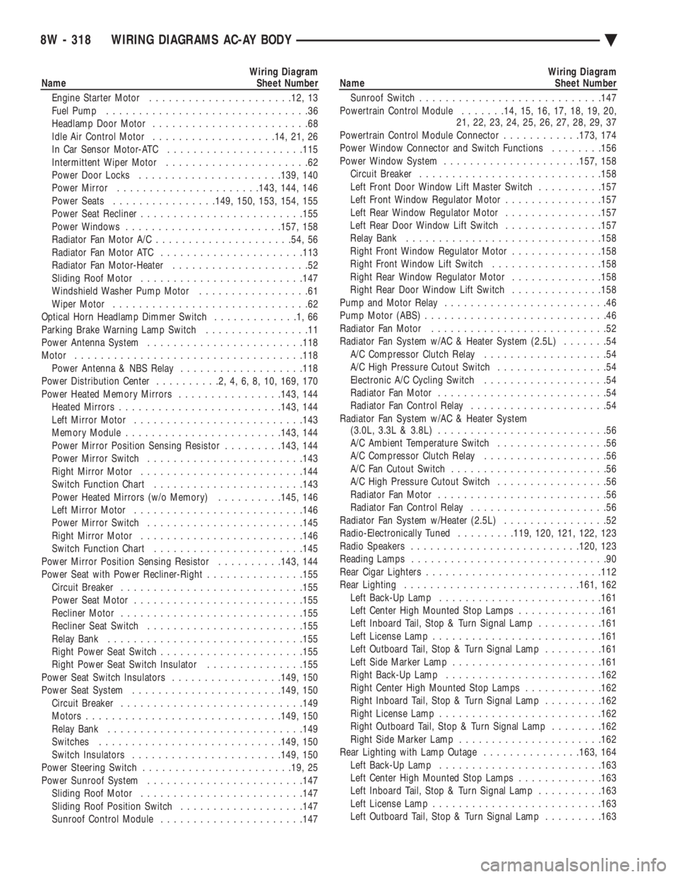
Wiring Diagram
Name Sheet Number
Engine Starter Motor ..................... .12, 13
Fuel Pump ...............................36
Headlamp Door Motor ........................68
Idle Air Control Motor .................. .14, 21, 26
In Car Sensor Motor-ATC .................... .115
Intermittent Wiper Motor ......................62
Power Door Locks ..................... .139, 140
Power Mirror ..................... .143, 144, 146
Power Seats ............... .149, 150, 153, 154, 155
Power Seat Recliner ........................ .155
Power Windows ....................... .157, 158
Radiator Fan Motor A/C .................... .54, 56
Radiator Fan Motor ATC ..................... .113
Radiator Fan Motor-Heater .....................52
Sliding Roof Motor ........................ .147
Windshield Washer Pump Motor .................61
Wiper Motor ..............................62
Optical Horn Headlamp Dimmer Switch .............1,66
Parking Brake Warning Lamp Switch ................11
Power Antenna System ....................... .118
Motor .................................. .118
Power Antenna & NBS Relay ...................118
Power Distribution Center ..........2,4,6,8,10, 169, 170
Power Heated Memory Mirrors ................143, 144
Heated Mirror s........................ .143, 144
Left Mirror Motor ......................... .143
Memory Module ....................... .143, 144
Power Mirror Position Sensing Resistor .........143, 144
Power Mirror Switch ....................... .143
Right Mirror Motor ........................ .144
Switch Function Chart ...................... .143
Power Heated Mirrors (w/o Memory) ..........145, 146
Left Mirror Motor ......................... .146
Power Mirror Switch ....................... .145
Right Mirror Motor ........................ .146
Switch Function Chart ...................... .145
Power Mirror Position Sensing Resistor ..........143, 144
Power Seat with Power Recliner-Right ...............155
Circuit Breaker ........................... .155
Power Seat Motor ......................... .155
Recliner Motor ........................... .155
Recliner Seat Switch ....................... .155
Relay Bank ............................. .155
Right Power Seat Switch ..................... .155
Right Power Seat Switch Insulator ...............155
Power Seat Switch Insulators .................149, 150
Power Seat System ...................... .149, 150
Circuit Breaker ........................... .149
Motors ............................. .149, 150
Relay Bank ............................. .149
Switches ........................... .149, 150
Switch Insulators ...................... .149, 150
Power Steering Switch ...................... .19, 25
Power Sunroof System ....................... .147
Sliding Roof Motor ........................ .147
Sliding Roof Position Switch ...................147
Sunroof Control Module ..................... .147Wiring Diagram
Name Sheet Number
Sunroof Switch ........................... .147
Powertrain Control Module .......14, 15, 16, 17, 18, 19, 20,
21, 22, 23, 24, 25, 26, 27, 28, 29, 37
Powertrain Control Module Connector ............173, 174
Power Window Connector and Switch Functions ........156
Power Window System .................... .157, 158
Circuit Breaker ........................... .158
Left Front Door Window Lift Master Switch ..........157
Left Front Window Regulator Motor ...............157
Left Rear Window Regulator Motor ...............157
Left Rear Door Window Lift Switch ...............157
Relay Bank ............................. .158
Right Front Window Regulator Motor ..............158
Right Front Window Lift Switch .................158
Right Rear Window Regulator Motor ..............158
Right Rear Door Window Lift Switch ..............158
Pump and Motor Relay .........................46
Pump Motor (ABS) ............................46
Radiator Fan Motor ...........................52
Radiator Fan System w/AC & Heater System (2.5L) .......54
A/C Compressor Clutch Relay ...................54
A/C High Pressure Cutout Switch .................54
Electronic A/C Cycling Switch ...................54
Radiator Fan Motor ..........................54
Radiator Fan Control Relay .....................54
Radiator Fan System w/AC & Heater System (3.0L, 3.3L & 3.8L) ..........................56
A/C Ambient Temperature Switch .................56
A/C Compressor Clutch Relay ...................56
A/C Fan Cutout Switch ........................56
A/C High Pressure Cutout Switch .................56
Radiator Fan Motor ..........................56
Radiator Fan Control Relay .....................56
Radiator Fan System w/Heater (2.5L) ................52
Radio-Electronically Tuned .........119, 120, 121, 122, 123
Radio Speakers ......................... .120, 123
Reading Lamps ..............................90
Rear Cigar Lighters .......................... .112
Rear Lighting .......................... .161, 162
Left Back-Up Lamp ........................ .161
Left Center High Mounted Stop Lamps .............161
Left Inboard Tail, Stop & Turn Signal Lamp ..........161
Left License Lamp ......................... .161
Left Outboard Tail, Stop & Turn Signal Lamp .........161
Left Side Marker Lamp ...................... .161
Right Back-Up Lamp ....................... .162
Right Center High Mounted Stop Lamps ............162
Right Inboard Tail, Stop & Turn Signal Lamp .........162
Right License Lamp ........................ .162
Right Outboard Tail, Stop & Turn Signal Lamp ........162
Right Side Marker Lamp ..................... .162
Rear Lighting with Lamp Outage ...............163, 164
Left Back-Up Lamp ........................ .163
Left Center High Mounted Stop Lamps .............163
Left Inboard Tail, Stop & Turn Signal Lamp ..........163
Left License Lamp ......................... .163
Left Outboard Tail, Stop & Turn Signal Lamp .........163
8W - 318 WIRING DIAGRAMS AC-AY BODY Ä
Page 1287 of 2438
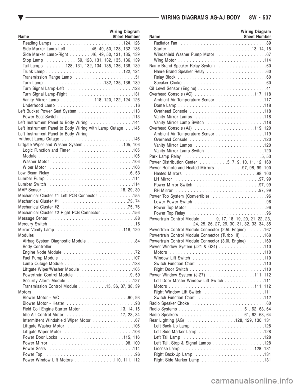
Wiring Diagram
Name Sheet Number
Reading Lamps ....................... .124, 126
Side Marker Lamp-Left .........45, 49, 50, 128, 132, 136
Side Marker Lamp-Right ........46, 49, 50, 131, 135, 139
Stop Lamp .......... .59, 128, 131, 132, 135, 136, 139
Tail Lamps .......128, 131, 132, 134, 135, 136, 138, 139
Trunk Lamp .......................... .122, 124
Transmission Range Lamp .....................51
Turn Lamp .................... .132, 135, 136, 139
Turn Signal Lamp-Left ...................... .128
Turn Signal Lamp-Right ..................... .131
Vanity Mirror Lamp ............118, 120, 122, 124, 126
Underhood Lamp ...........................16
Left Bucket Power Seat System ...................113
Power Seat Switch ........................ .113
Left Instrument Panel to Body Wiring ...............144
Left Instrument Panel to Body Wiring with Lamp Outage . . .145
Left Instrument Panel to Body Wiring without Lamp Outage ........................ .146
Liftgate Wiper and Washer System ..............105, 106
Logic Function and Timer .................... .105
Module ................................ .105
Washer Motor ........................... .106
Wiper Motor ............................ .106
Low Beam Relay ...........................6,53
Lumbar Pump ............................. .114
Lumbar Switch ............................ .114
MAP Sensor .......................... .18, 29, 30
Mechanical Cluster #1 Left PCB Connector ............155
Mechanical Cluster #1 ...................... .73, 74
Mechanical Cluster #2 ...................... .75, 76
Mechanical Cluster #2 Right PCB Connector ...........156
Message Center ..............................88
Mercury Switch ..............................16
Mirror Vanity Lamp ...................... .118, 120
Modules Airbag System Diagnostic Module .................84
Body Controller
Engine Node Module .........................72
Fuel Pump Module ........................ .107
Lamp Outage Module ....................... .138
Liftgate Wiper/Washer Module ..................105
Powertrain Control Module ...................9,59
Security Alarm Module ...................... .127
Transmission Control Module ..........15, 36, 37, 38, 39
Motors Blower Motor - A/C ...................... .90, 93
Blower Motor - Heater ........................93
Field Coil Engine Starter Motor ..............13, 14, 15
Idle Air Control Motor .................. .17, 23, 34
Intermittent Windshield Wiper Motor ...............67
Liftgate Washer Motor ...................... .106
Liftgate Wiper Motor ....................... .106
Power Door Locks ..................... .115, 116
Power Mirror ......................... .98, 100
Power Seats ............................ .114
Power Top ...............................96
Power Window Lift Motors ..............110, 111, 112Wiring Diagram
Name Sheet Number
Radiator Fan ..............................89
Starter ............................ .13, 14, 15
Windshield Washer Pump Motor .................67
Wing Motor ............................. .114
Name Brand Speaker Relay System .................60
Name Brand Speaker Relay .....................60
Relay Block ...............................60
Speaker Choke .............................60
Oil Level Sensor (Engine) ........................41
Overhead Console (AG) .................... .117, 118
Ambient Air Temperature Sensor .................117
Dome Lamp ............................. .118
Overhead Console ......................... .118
Vanity Mirror Lamps ....................... .118
Vanity Mirror Lamp Switch ................... .118
Overhead Console (AJ) .................... .119, 120
Ambient Air Temperature Sensor .................119
Overhead Console ......................... .120
Vanity Mirror Lamps ....................... .120
Vanity Mirror Lamp Switch ................... .120
Park Lamp Relay ...........................5,53
Power Distribution Center ..........5,7,9,10,11,12,160
Power Remote and Heated Mirrors .........97, 98, 99, 100
Heated Mirrors ........................ .98, 100
LH Mirror ............................ .97, 99
Power Mirror Switch ..................... .97, 99
RH Mirror ............................ .97, 99
Power Top System (Convertible) ...................96
Lower Power Switch .........................96
Power Top Motor ...........................96
Power Top Relay ...........................96
Powertrain Control Module ......9,17,18,19,20,21,22,23,
24, 25, 26, 27, 29, 30, 31, 32, 33, 34, 35
Powertrain Control Module Connector (2.5L Engine) ......167
Powertrain Control Module Connector (Turbo III) ........168
Powertrain Control Module Connector (3.0L Engine) ......169
Power Window System (J21 & G24) ................110
Motors ................................ .110
Window Lift Switch ........................ .110
Switch Function Chart ...................... .110
Right Door Switch ......................... .110
Power Window System (J-27) ................111, 112
Left Door Master Window Lift Switch ..............111
Motors ............................. .111, 112
Right Window Lift Switch .................... .111
Switch Function Chart ...................... .112
Radio Speaker Choke ..........................60
Radio Systems ...................... .61, 62, 63, 64
Radio Speakers ..................... .61, 62, 63, 64
Rear Lighting (AG) ................ .128, 129, 130, 131
Left Back-Up Lamp ........................ .128
Left Side Marker Lamp ...................... .128
Left Tail Lamp ........................... .128
Left Tail, Stop & Signal Lamps ..................128
License Lamp ........................ .128, 131
Right Back-Up Lamp ....................... .131
Right Side Marker Lamp ..................... .131
Ä WIRING DIAGRAMS AG-AJ BODY 8W - 537
Page 1594 of 2438
springs using Tool C-3422-B. (2) Remove valve retaining locks, valve spring re-
tainers, valve stem seals and valve springs. (3) Before removing valves, remove any burrs
from valve stem lock grooves to prevent damage
to the valve guides. Identify valves to insure instal-
lation in original location.
VALVE INSPECTION (1) Clean valves thoroughly and discard burned,
warped and cracked valves. (2) Measure valve stems for wear.
(3) If valve stems are worn more than 0.05 mm (.002
inch.) replace valve.
VALVE GUIDES
(1) Remove carbon and varnish deposits from inside
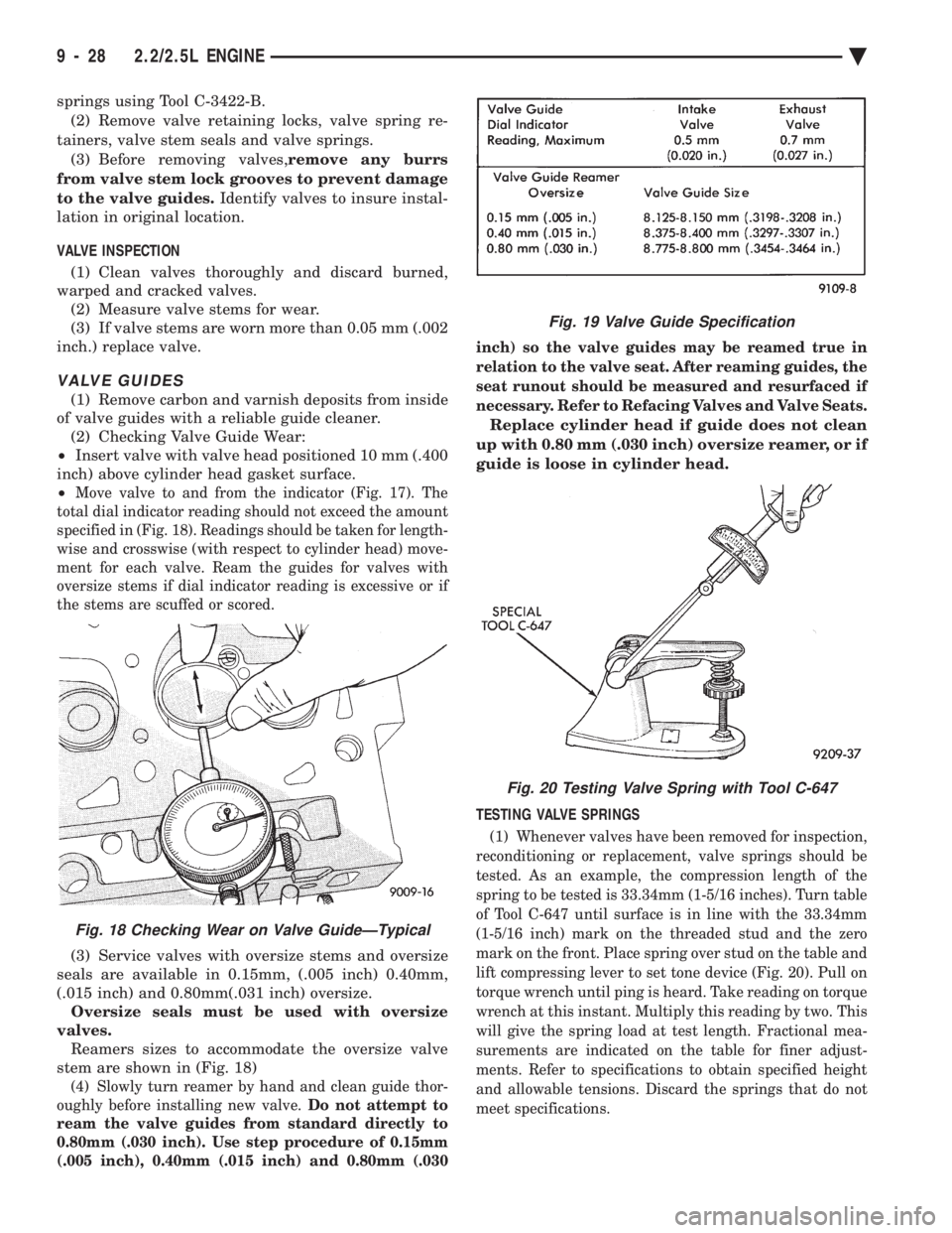
of valve guides with a reliable guide cleaner. (2) Checking Valve Guide Wear:
² Insert valve with valve head positioned 10 mm (.400
inch) above cylinder head gasket surface.
²
Move valve to and from the indicator (Fig. 17). The
total dial indicator reading should not exceed the amount
specified in (Fig. 18). Readings should be taken for length-
wise and crosswise (with respect to cylinder head) move-
ment for each valve. Ream the guides for valves with
oversize stems if dial indicator reading is excessive or if
the stems are scuffed or scored.
(3) Service valves with oversize stems and oversize
seals are available in 0.15mm, (.005 inch) 0.40mm,
(.015 inch) and 0.80mm(.031 inch) oversize. Oversize seals must be used with oversize
valves. Reamers sizes to accommodate the oversize valve
stem are shown in (Fig. 18)
(4) Slowly turn reamer by hand and clean guide thor-
oughly before installing new valve. Do not attempt to
ream the valve guides from standard directly to
0.80mm (.030 inch). Use step procedure of 0.15mm
(.005 inch), 0.40mm (.015 inch) and 0.80mm (.030 inch) so the valve guides may be reamed true in
relation to the valve seat. After reaming guides, the
seat runout should be measured and resurfaced if
necessary. Refer to Refacing Valves and Valve Seats.
Replace cylinder head if guide does not clean
up with 0.80 mm (.030 inch) oversize reamer, or if
guide is loose in cylinder head.
TESTING VALVE SPRINGS
(1) Whenever valves have been removed for inspection,
reconditioning or replacement, valve springs should be
tested. As an example, the compression length of the
spring to be tested is 33.34mm (1-5/16 inches). Turn table
of Tool C-647 until surface is in line with the 33.34mm
(1-5/16 inch) mark on the threaded stud and the zero
mark on the front. Place spring over stud on the table and
lift compressing lever to set tone device (Fig. 20). Pull on
torque wrench until ping is heard. Take reading on torque
wrench at this instant. Multiply this reading by two. This
will give the spring load at test length. Fractional mea-
surements are indicated on the table for finer adjust-
ments. Refer to specifications to obtain specified height
and allowable tensions. Discard the springs that do not
meet specifications.
Fig. 18 Checking Wear on Valve GuideÐTypical
Fig. 19 Valve Guide Specification
Fig. 20 Testing Valve Spring with Tool C-647
9 - 28 2.2/2.5L ENGINE Ä
Page 1595 of 2438
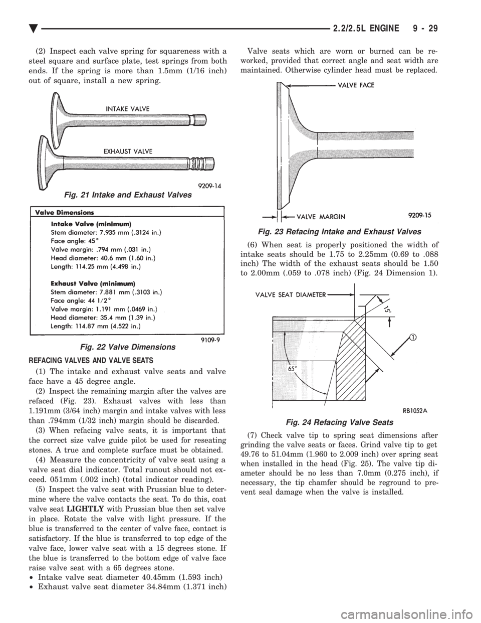
(2) Inspect each valve spring for squareness with a
steel square and surface plate, test springs from both
ends. If the spring is more than 1.5mm (1/16 inch)
out of square, install a new spring.
REFACING VALVES AND VALVE SEATS (1) The intake and exhaust valve seats and valve
face have a 45 degree angle.
(2) Inspect the remaining margin after the valves are
refaced (Fig. 23). Exhaust valves with less than
1.191mm (3/64 inch) margin and intake valves with less
than .794mm (1/32 inch) margin should be discarded. (3) When refacing valve seats, it is important that
the correct size valve guide pilot be used for reseating
stones. A true and complete surface must be obtained.
(4) Measure the concentricity of valve seat using a
valve seat dial indicator. Total runout should not ex-
ceed. 051mm (.002 inch) (total indicator reading).
(5) Inspect the valve seat with Prussian blue to deter-
mine where the valve contacts the seat. To do this, coat
valve seat LIGHTLY with Prussian blue then set valve
in place. Rotate the valve with light pressure. If the
blue is transferred to the center of valve face, contact is
satisfactory. If the blue is transferred to top edge of the
valve face, lower valve seat with a 15 degrees stone. If
the blue is transferred to the bottom edge of valve face
raise valve seat with a 65 degrees stone.
² Intake valve seat diameter 40.45mm (1.593 inch)
² Exhaust valve seat diameter 34.84mm (1.371 inch)
Valve seats which are worn or burned can be re-
worked, provided that correct angle and seat width are
maintained. Otherwise cylinder head must be replaced.
(6) When seat is properly positioned the width of
intake seats should be 1.75 to 2.25mm (0.69 to .088
inch) The width of the exhaust seats should be 1.50
to 2.00mm (.059 to .078 inch) (Fig. 24 Dimension 1).
(7) Check valve tip to spring seat dimensions after
grinding the valve seats or faces. Grind valve tip to get
49.76 to 51.04mm (1.960 to 2.009 inch) over spring seat
when installed in the head (Fig. 25). The valve tip di-
ameter should be no less than 7.0mm (0.275 inch), if
necessary, the tip chamfer should be reground to pre-
vent seal damage when the valve is installed.
Fig. 21 Intake and Exhaust Valves
Fig. 22 Valve Dimensions
Fig. 23 Refacing Intake and Exhaust Valves
Fig. 24 Refacing Valve Seats
Ä 2.2/2.5L ENGINE 9 - 29
Page 1596 of 2438
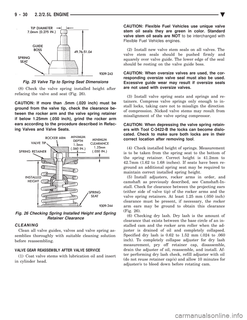
(8) Check the valve spring installed height after
refacing the valve and seat (Fig. 26).
CAUTION: If more than .5mm (.020 inch) must be
ground from the valve tip, check the clearance be-
tween the rocker arm and the valve spring retainer
if below 1.25mm (.050 inch), grind the rocker arm
ears according to the procedure described in Refac-
ing Valves and Valve Seats.
CLEANING
Clean all valve guides, valves and valve spring as-
semblies thoroughly with suitable cleaning solution
before reassembling.
VALVE GEAR REASSEMBLY AFTER VALVE SERVICE (1) Coat valve stems with lubrication oil and insert
in cylinder head. CAUTION: Flexible Fuel Vehicles use unique valve
stem oil seals they are green in color. Standard
valve stem oil seals are NOT to be interchanged with
Flexible Fuel Vehicles engines.
(2) Install new valve stem seals on all valves. The
valve stem seals should be pushed firmly and
squarely over valve guide. The lower edge of the seal
should be resting on the valve guide boss.
CAUTION: When oversize valves are used, the cor-
responding oversize valve seal must also be used.
Excessive guide wear may result if oversize seals
are not used with oversize valves.
(3) Install valve spring seats and springs and re-
tainers. Compress valve springs only enough to in-
stall locks, taking care not to misalign the direction
of compression. Nicked valve stems may result from
misalignment of the valve spring compressor.
CAUTION: When depressing the valve spring retain-
ers with Tool C-3422-B the locks can become dislo-
cated. Check to make sure both locks are in their
correct location after removing tool .
(4) Check installed height of springs. Measurement
is to be taken from the spring seat to the bottom of
the spring retainer. Correct height is 41.2mm to
42.7mm (1.62 to 1.68 inches). If seats have been re-
ground an additional spring seat may be required to
maintain correct installed spring height. (5) Install adjusters, rocker arms in order, and
camshaft as previously described, see Camshaft-In-
stall. Check for clearance between the projecting ears
(either side of valve tip) of the rocker arms and the
valve spring retainers. At least 1.25 mm (.050 inch)
clearance must be present, if necessary, the rocker
arm ears may be ground to obtain this clearance
(Fig. 26). (6) Checking dry lash. Dry lash is the amount of
clearance that exists between the base circle of an in-
stalled cam and the rocker arm roller when the ad-
juster is drained of oil and completely collapsed.
Specified dry lash is 0.62 to 1.52 mm (.024 to .060
inch). To completely collapse adjuster for dry lash
measurement, pry off retainer cap, disassemble,
drain the adjuster of oil, reassemble, and install. Af-
ter performing dry lash check, refill adjuster with oil
(do not reuse retainer cap/s) and allow 10 minutes for
adjuster/s to bleed down before rotating cam.
Fig. 25 Valve Tip to Spring Seat Dimensions
Fig. 26 Checking Spring Installed Height and Spring Retainer Clearance
9 - 30 2.2/2.5L ENGINE Ä
Page 1605 of 2438
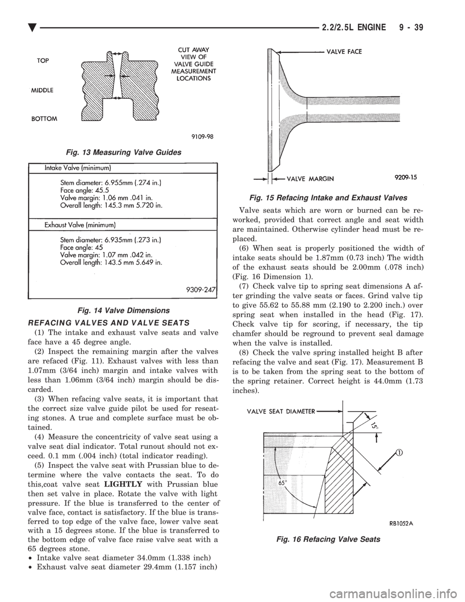
REFACING VALVES AND VALVE SEATS
(1) The intake and exhaust valve seats and valve
face have a 45 degree angle. (2) Inspect the remaining margin after the valves
are refaced (Fig. 11). Exhaust valves with less than
1.07mm (3/64 inch) margin and intake valves with
less than 1.06mm (3/64 inch) margin should be dis-
carded. (3) When refacing valve seats, it is important that
the correct size valve guide pilot be used for reseat-
ing stones. A true and complete surface must be ob-
tained. (4) Measure the concentricity of valve seat using a
valve seat dial indicator. Total runout should not ex-
ceed. 0.1 mm (.004 inch) (total indicator reading). (5) Inspect the valve seat with Prussian blue to de-
termine where the valve contacts the seat. To do
this,coat valve seat LIGHTLYwith Prussian blue
then set valve in place. Rotate the valve with light
pressure. If the blue is transferred to the center of
valve face, contact is satisfactory. If the blue is trans-
ferred to top edge of the valve face, lower valve seat
with a 15 degrees stone. If the blue is transferred to
the bottom edge of valve face raise valve seat with a
65 degrees stone.
² Intake valve seat diameter 34.0mm (1.338 inch)
² Exhaust valve seat diameter 29.4mm (1.157 inch) Valve seats which are worn or burned can be re-
worked, provided that correct angle and seat width
are maintained. Otherwise cylinder head must be re-
placed. (6) When seat is properly positioned the width of
intake seats should be 1.87mm (0.73 inch) The width
of the exhaust seats should be 2.00mm (.078 inch)
(Fig. 16 Dimension 1). (7) Check valve tip to spring seat dimensions A af-
ter grinding the valve seats or faces. Grind valve tip
to give 55.62 to 55.88 mm (2.190 to 2.200 inch.) over
spring seat when installed in the head (Fig. 17).
Check valve tip for scoring, if necessary, the tip
chamfer should be reground to prevent seal damage
when the valve is installed. (8) Check the valve spring installed height B after
refacing the valve and seat (Fig. 17). Measurement B
is to be taken from the spring seat to the bottom of
the spring retainer. Correct height is 44.0mm (1.73
inches).
Fig. 13 Measuring Valve Guides
Fig. 14 Valve Dimensions
Fig. 15 Refacing Intake and Exhaust Valves
Fig. 16 Refacing Valve Seats
Ä 2.2/2.5L ENGINE 9 - 39
Page 1606 of 2438
VALVE GEAR REASSEMBLY AFTER VALVE SERVICE
(1) Coat valve stems with lubrication oil and insert
in cylinder head. (2) Install new valve stem seals on all valves. The
valve stem seals should be pushed firmly and
squarely over valve guide. The lower edge of the seal
should be resting on the valve guide boss. (3) Install valve spring seats and springs and re-
tainers. Compress valve springs only enough to in-
stall locks, taking care not to misalign the direction
of compression. Nicked valve stems may result from
misalignment of the valve spring compressor.
CAUTION: When depressing the valve spring retain-
ers with Valve Spring Compressor Tool C-3422-B
with adopters 6537 and 6526 (Fig. 11) the locks can
become dislocated. Check to make sure both locks
are in their correct location after removing tool.
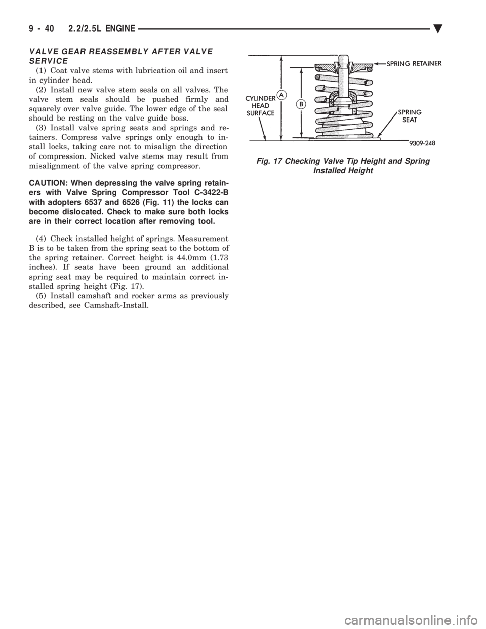
(4) Check installed height of springs. Measurement
B is to be taken from the spring seat to the bottom of
the spring retainer. Correct height is 44.0mm (1.73
inches). If seats have been ground an additional
spring seat may be required to maintain correct in-
stalled spring height (Fig. 17). (5) Install camshaft and rocker arms as previously
described, see Camshaft-Install.
Fig. 17 Checking Valve Tip Height and Spring Installed Height
9 - 40 2.2/2.5L ENGINE Ä