1993 CHEVROLET PLYMOUTH ACCLAIM suspension
[x] Cancel search: suspensionPage 68 of 2438
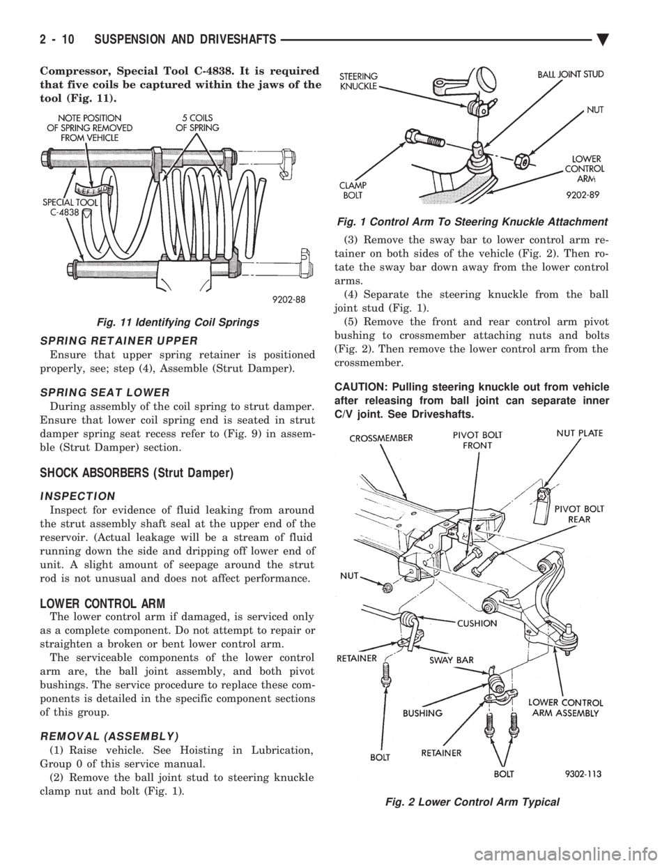
Compressor, Special Tool C-4838. It is required
that five coils be captured within the jaws of the
tool (Fig. 11).
SPRING RETAINER UPPER
Ensure that upper spring retainer is positioned
properly, see; step (4), Assemble (Strut Damper).
SPRING SEAT LOWER
During assembly of the coil spring to strut damper.
Ensure that lower coil spring end is seated in strut
damper spring seat recess refer to (Fig. 9) in assem-
ble (Strut Damper) section.
SHOCK ABSORBERS (Strut Damper)
INSPECTION
Inspect for evidence of fluid leaking from around
the strut assembly shaft seal at the upper end of the
reservoir. (Actual leakage will be a stream of fluid
running down the side and dripping off lower end of
unit. A slight amount of seepage around the strut
rod is not unusual and does not affect performance.
LOWER CONTROL ARM
The lower control arm if damaged, is serviced only
as a complete component. Do not attempt to repair or
straighten a broken or bent lower control arm. The serviceable components of the lower control
arm are, the ball joint assembly, and both pivot
bushings. The service procedure to replace these com-
ponents is detailed in the specific component sections
of this group.
REMOVAL (ASSEMBLY)
(1) Raise vehicle. See Hoisting in Lubrication,
Group 0 of this service manual. (2) Remove the ball joint stud to steering knuckle
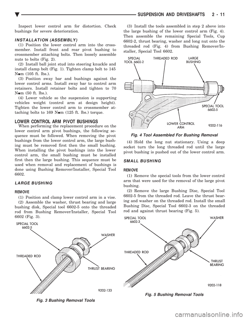
clamp nut and bolt (Fig. 1). (3) Remove the sway bar to lower control arm re-
tainer on both sides of the vehicle (Fig. 2). Then ro-
tate the sway bar down away from the lower control
arms. (4) Separate the steering knuckle from the ball
joint stud (Fig. 1). (5) Remove the front and rear control arm pivot
bushing to crossmember attaching nuts and bolts
(Fig. 2). Then remove the lower control arm from the
crossmember.
CAUTION: Pulling steering knuckle out from vehicle
after releasing from ball joint can separate inner
C/V joint. See Driveshafts.
Fig. 11 Identifying Coil Springs
Fig. 1 Control Arm To Steering Knuckle Attachment
Fig. 2 Lower Control Arm Typical
2 - 10 SUSPENSION AND DRIVESHAFTS Ä
Page 69 of 2438
Inspect lower control arm for distortion. Check
bushings for severe deterioration.
INSTALLATION (ASSEMBLY)
(1) Position the lower control arm into the cross-
member. Install front and rear pivot bushing to
crossmember attaching bolts. Then loosely assemble
nuts to bolts (Fig. 2). (2) Install ball joint stud into steering knuckle and
install clamp bolt (Fig. 1). Tighten clamp bolt to 145
N Im (105 ft. lbs.).
(3) Position sway bar and bushings against the
lower control arms. Install sway bar to control arm
retainers. Install retainer bolts and tighten to 70
N Im (50 ft. lbs.).
(4) Lower vehicle so the suspension is supporting
vehicles weight (control arm at design height).
Tighten the lower control arm to crossmember at-
taching bolts to 169 N Im (125 ft. lbs.) torque.
LOWER CONTROL ARM PIVOT BUSHINGS
When performing the replacement procedure on the
lower control arm pivot bushings, the following se-
quence must be followed. When removing the pivot
bushings from the lower control arm, the large bush-
ing must be removed first then the small bushing.
When installing the pivot bushings into the lower
control arm, the small bushing must be installed
first then the large bushing. This sequence must be
used when removal and replacement of bushings is
done using Bushing Remover/Installer, Special Tool
6602.
LARGE BUSHING
REMOVE
(1) Position and clamp lower control arm in a vise.
(2) Assemble the washer, thrust bearing and large
bushing disk, Special tool 6602-5 onto the threaded
rod from Bushing Remover/Installer, Special Tool
6602 (Fig. 3). (3) Install the tools assembled in step 2 above into
the large bushing of the lower control arm (Fig. 4).
Then assemble the remaining Special Tools, Cup
6602-2, thrust bearing, washer and long nut onto the
threaded rod (Fig. 4) from Bushing Remover/In-
staller, Special Tool 6602.
(4) Hold the long nut stationary. Using a deep
socket turn the long threaded rod until the large
pivot bushing is pushed out of the lower control arm.
SMALL BUSHING
REMOVE
(1) Remove the special tools from the lower control
arm that were used for the removal of the large pivot
bushing. (2) Remove the large Bushing Disc, Special Tool
6602-5 from the threaded rod. Leave the thrust bear-
ing and washer on the threaded rod. Install the small
Bushing Disc, Special Tool 6602-3 on the threaded
rod and against thrust bearing (Fig. 5).
Fig. 3 Bushing Removal Tools
Fig. 4 Tool Assembled For Bushing Removal
Fig. 5 Bushing Removal Tools
Ä SUSPENSION AND DRIVESHAFTS 2 - 11
Page 70 of 2438
(3) Install the tools assembled in step 2 above
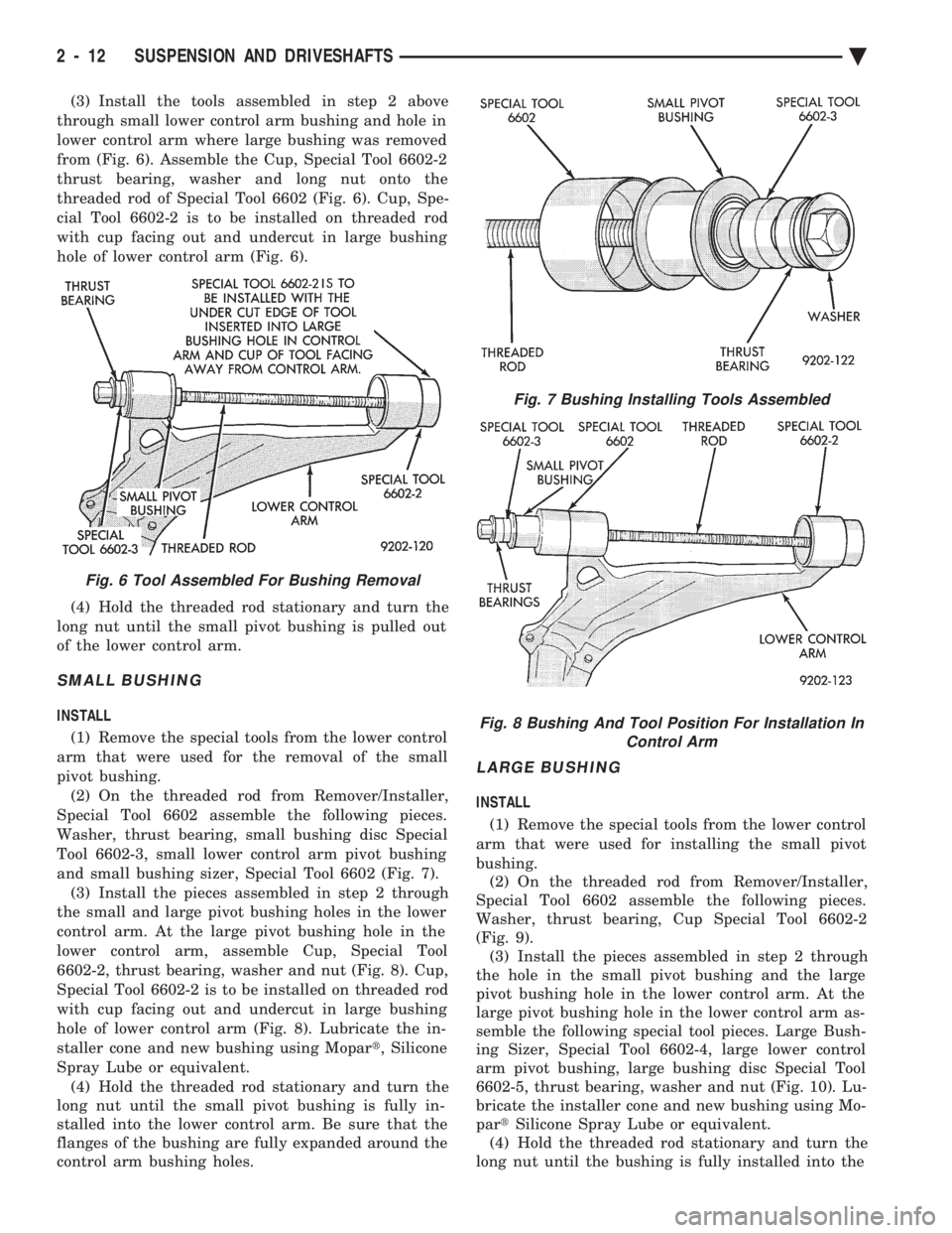
through small lower control arm bushing and hole in
lower control arm where large bushing was removed
from (Fig. 6). Assemble the Cup, Special Tool 6602-2
thrust bearing, washer and long nut onto the
threaded rod of Special Tool 6602 (Fig. 6). Cup, Spe-
cial Tool 6602-2 is to be installed on threaded rod
with cup facing out and undercut in large bushing
hole of lower control arm (Fig. 6).
(4) Hold the threaded rod stationary and turn the
long nut until the small pivot bushing is pulled out
of the lower control arm.
SMALL BUSHING
INSTALL
(1) Remove the special tools from the lower control
arm that were used for the removal of the small
pivot bushing. (2) On the threaded rod from Remover/Installer,
Special Tool 6602 assemble the following pieces.
Washer, thrust bearing, small bushing disc Special
Tool 6602-3, small lower control arm pivot bushing
and small bushing sizer, Special Tool 6602 (Fig. 7). (3) Install the pieces assembled in step 2 through
the small and large pivot bushing holes in the lower
control arm. At the large pivot bushing hole in the
lower control arm, assemble Cup, Special Tool
6602-2, thrust bearing, washer and nut (Fig. 8). Cup,
Special Tool 6602-2 is to be installed on threaded rod
with cup facing out and undercut in large bushing
hole of lower control arm (Fig. 8). Lubricate the in-
staller cone and new bushing using Mopar t, Silicone
Spray Lube or equivalent. (4) Hold the threaded rod stationary and turn the
long nut until the small pivot bushing is fully in-
stalled into the lower control arm. Be sure that the
flanges of the bushing are fully expanded around the
control arm bushing holes.
LARGE BUSHING
INSTALL
(1) Remove the special tools from the lower control
arm that were used for installing the small pivot
bushing. (2) On the threaded rod from Remover/Installer,
Special Tool 6602 assemble the following pieces.
Washer, thrust bearing, Cup Special Tool 6602-2
(Fig. 9). (3) Install the pieces assembled in step 2 through
the hole in the small pivot bushing and the large
pivot bushing hole in the lower control arm. At the
large pivot bushing hole in the lower control arm as-
semble the following special tool pieces. Large Bush-
ing Sizer, Special Tool 6602-4, large lower control
arm pivot bushing, large bushing disc Special Tool
6602-5, thrust bearing, washer and nut (Fig. 10). Lu-
bricate the installer cone and new bushing using Mo-
par tSilicone Spray Lube or equivalent.
(4) Hold the threaded rod stationary and turn the
long nut until the bushing is fully installed into the
Fig. 6 Tool Assembled For Bushing Removal
Fig. 7 Bushing Installing Tools Assembled
Fig. 8 Bushing And Tool Position For Installation In Control Arm
2 - 12 SUSPENSION AND DRIVESHAFTS Ä
Page 71 of 2438
control arm. Be sure that the flanges of the bushing
are fully expanded around the control arm bushing
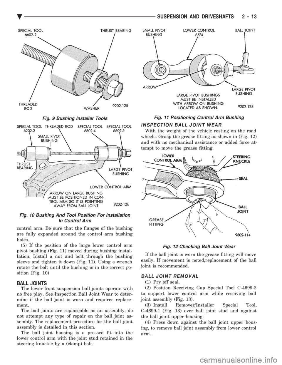
holes. (5) If the position of the large lower control arm
pivot bushing (Fig. 11) moved during bushing instal-
lation. Install a nut and bolt through the bushing
sleeve and tighten it down (Fig. 11). Using a wrench
rotate the bolt until the bushing is in the correct po-
sition (Fig. 10)
BALL JOINTS
The lower front suspension ball joints operate with
no free play. See Inspection Ball Joint Wear to deter-
mine if the ball joint is worn and requires replace-
ment. The ball joints are replaceable as an assembly, do
not attempt any type of repair on the ball joint as-
sembly. The replacement procedure for the ball joint
assembly is detailed in this section. The ball joint housing is a pressed fit into the
lower control arm with the joint stud retained in the
steering knuckle by a (clamp) bolt.
INSPECTION BALL JOINT WEAR
With the weight of the vehicle resting on the road
wheels. Grasp the grease fitting as shown in (Fig. 12)
and with no mechanical assistance or added force at-
tempt to move the grease fitting.
If the ball joint is worn the grease fitting will move
easily. If movement is noted,replacement of the ball
joint is recommended.
BALL JOINT REMOVAL
(1) Pry off seal.
(2) Position Receiving Cup Special Tool C-4699-2
to support lower control arm while receiving ball
joint assembly (Fig. 13). (3) Install Remover/Installer Special Tool,
C-4699-1 (Fig. 13) over ball joint stud and against
the ball joint upper housing. (4) Press down against the ball joint upper hous-
ing, to remove ball joint assembly from lower control
arm.
Fig. 9 Bushing Installer Tools
Fig. 10 Bushing And Tool Position For Installation In Control Arm
Fig. 11 Positioning Control Arm Bushing
Fig. 12 Checking Ball Joint Wear
Ä SUSPENSION AND DRIVESHAFTS 2 - 13
Page 72 of 2438
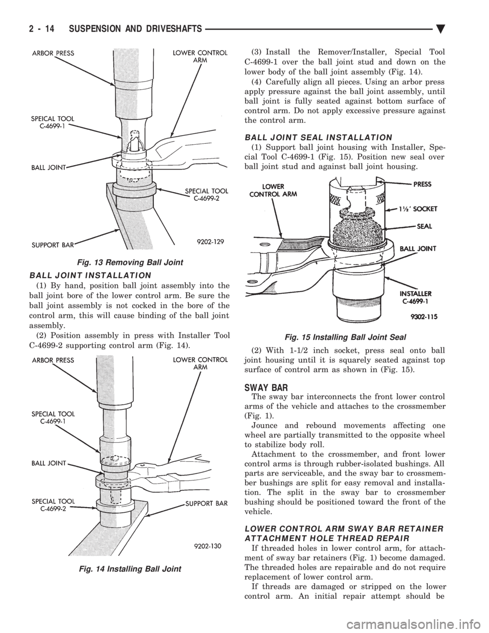
BALL JOINT INSTALLATION
(1) By hand, position ball joint assembly into the
ball joint bore of the lower control arm. Be sure the
ball joint assembly is not cocked in the bore of the
control arm, this will cause binding of the ball joint
assembly. (2) Position assembly in press with Installer Tool
C-4699-2 supporting control arm (Fig. 14). (3) Install the Remover/Installer, Special Tool
C-4699-1 over the ball joint stud and down on the
lower body of the ball joint assembly (Fig. 14). (4) Carefully align all pieces. Using an arbor press
apply pressure against the ball joint assembly, until
ball joint is fully seated against bottom surface of
control arm. Do not apply excessive pressure against
the control arm.
BALL JOINT SEAL INSTALLATION
(1) Support ball joint housing with Installer, Spe-
cial Tool C-4699-1 (Fig. 15). Position new seal over
ball joint stud and against ball joint housing.
(2) With 1-1/2 inch socket, press seal onto ball
joint housing until it is squarely seated against top
surface of control arm as shown in (Fig. 15).
SWAY BAR
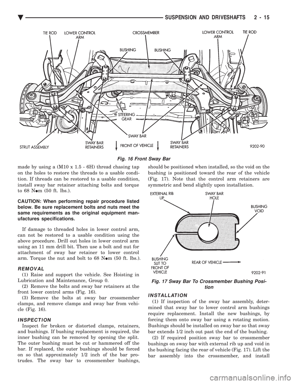
The sway bar interconnects the front lower control
arms of the vehicle and attaches to the crossmember
(Fig. 1). Jounce and rebound movements affecting one
wheel are partially transmitted to the opposite wheel
to stabilize body roll. Attachment to the crossmember, and front lower
control arms is through rubber-isolated bushings. All
parts are serviceable, and the sway bar to crossmem-
ber bushings are split for easy removal and installa-
tion. The split in the sway bar to crossmember
bushing should be positioned toward the front of the
vehicle.
LOWER CONTROL ARM SWAY BAR RETAINER ATTACHMENT HOLE THREAD REPAIR
If threaded holes in lower control arm, for attach-
ment of sway bar retainers (Fig. 1) become damaged.
The threaded holes are repairable and do not require
replacement of lower control arm. If threads are damaged or stripped on the lower
control arm. An initial repair attempt should be
Fig. 13 Removing Ball Joint
Fig. 14 Installing Ball Joint
Fig. 15 Installing Ball Joint Seal
2 - 14 SUSPENSION AND DRIVESHAFTS Ä
Page 73 of 2438
made by using a (M10 x 1.5 - 6H) thread chasing tap
on the holes to restore the threads to a usable condi-
tion. If threads can be restored to a usable condition,
install sway bar retainer attaching bolts and torque
to 68 N Im (50 ft. lbs.).
CAUTION: When performing repair procedure listed
below. Be sure replacement bolts and nuts meet the
same requirements as the original equipment man-
ufactures specifications.
If damage to threaded holes in lower control arm,
can not be restored to a usable condition using the
above procedure. Drill out holes in lower control arm
using an 11 mm drill bit. Then use a bolt and nut for
attachment of sway bar retainer to lower control
arm. Torque the nut and bolt to 68 N Im (50 ft. lbs.).
REMOVAL
(1) Raise and support the vehicle. See Hoisting in
Lubrication and Maintenance, Group 0. (2) Remove the bolts and sway bar retainers at the
front lower control arms (Fig. 16). (3) Remove the bolts at sway bar crossmember
clamps, and remove clamps and sway bar from vehi-
cle (Fig. 16).
INSPECTION
Inspect for broken or distorted clamps, retainers,
and bushings. If bushing replacement is required, the
inner bushing can be removed by opening the split.
The outer bushing must be cut or hammered off the
bar. If replaced, the outer bushings should be forced
on so that approximately 1/2 inch of the bar pro-
trudes. The sway bar to crossmember bushings, should be positioned when installed, so the void on the
bushing is positioned toward the rear of the vehicle
(Fig. 17). Note that the control arm retainers are
symmetric and bend slightly upon installation.
INSTALLATION
(1) If inspection of the sway bar assembly, deter-
mined that sway bar to lower control arm bushings
require replacement. Install the new bushings, by
forcing them onto sway bar using a rotating motion.
Bushings should be installed on sway bar so that sway
bar extends 1/2 inch out past the end of the bushing. (2) If required position sway bar to crossmember
bushings on sway bar with external rib up and void in
the bushing facing the rear of vehicle (Fig. 17). Lift the
bar assembly into the crossmember, and install
Fig. 16 Front Sway Bar
Fig. 17 Sway Bar To Crossmember Bushing Posi- tion
Ä SUSPENSION AND DRIVESHAFTS 2 - 15
Page 74 of 2438

the lower clamps and bolts. The center offset in the
sway bar should be oriented toward the front of the
vehicle (Fig. 16)(3) Position bushing retainers on lower control arms
and install bolts (Fig. 16). (4) With lower control arms raised to design height,
tighten all retainer attaching bolts to 70 N Im (50 ft.
lbs.) torque. (5) Lower vehicle.
KNUCKLE (FRONT SUSPENSION)
The front suspension knuckle (Fig. 1) provides for
steering control of the vehicle. Supports the brake
caliper and absorbs the loads exerted during vehicle
braking. It also supports the front (driving) hub and
bearing and stub axle assembly. The front suspension knuckle also provides the abil-
ity to align the front wheels of the vehicle. This is done
by allowing for front wheel camber adjustment and the
ability for front tire Toe adjustments The front suspension knuckle is not a serviceable
component. Do not attempt to straighten or repair the
front suspension knuckle in any way. Service repair or replacement of the front (drive) hub
and bearing, can be done with the front suspension
knuckle remaining on the vehicle.
REMOVAL
(1) Remove the cotter pin, hub nut lock and spring
washer from the front axle (Fig. 2). (2) Loosen hub nut while the vehicle is on the floor
with the brakes applied (Fig. 3). The hub and drive-
shaft are splined together through the knuckle
(bearing) and retained by the hub nut. (3) Raise and support the vehicle. See Hoisting in
Lubrication and Maintenance, Group 0. (4) Remove the wheel lug nuts, front tire and
wheel assembly and hub nut and washer. (5) Remove the brake caliper adapter to steering
knuckle attaching bolts and washers (Fig. 1). Re-
move the brake caliper and adapter from the steering
knuckle and braking disc. Support brake caliper/
adapter assembly using a wire hook and not by hy-
draulic hose (Fig. 4). (6) Remove the braking disc from the front hub/
bearing assembly (Fig. 5). (7) Remove the cotter pin and nut from the tie rod
end. Remove the tie rod end from the steering
knuckle arm using Puller, Special Tool C-3894-A
(Fig. 6). (8) Remove the clamp nut and bolt (Fig. 7) secur-
ing the ball joint stud into the steering knuckle. (9) Separate ball joint stud from knuckle assembly
by prying down on lower control arm. Pull knuckle
assembly out and away from driveshaft (Fig. 8).
Fig. 2 Remove Cotter Pin, Hub Nut Lock, & Spring Washer
Fig. 3 Loosen Hub Nut
Fig. 1 Front Knuckle Assembly (Typical)
2 - 16 SUSPENSION AND DRIVESHAFTS Ä
Page 75 of 2438
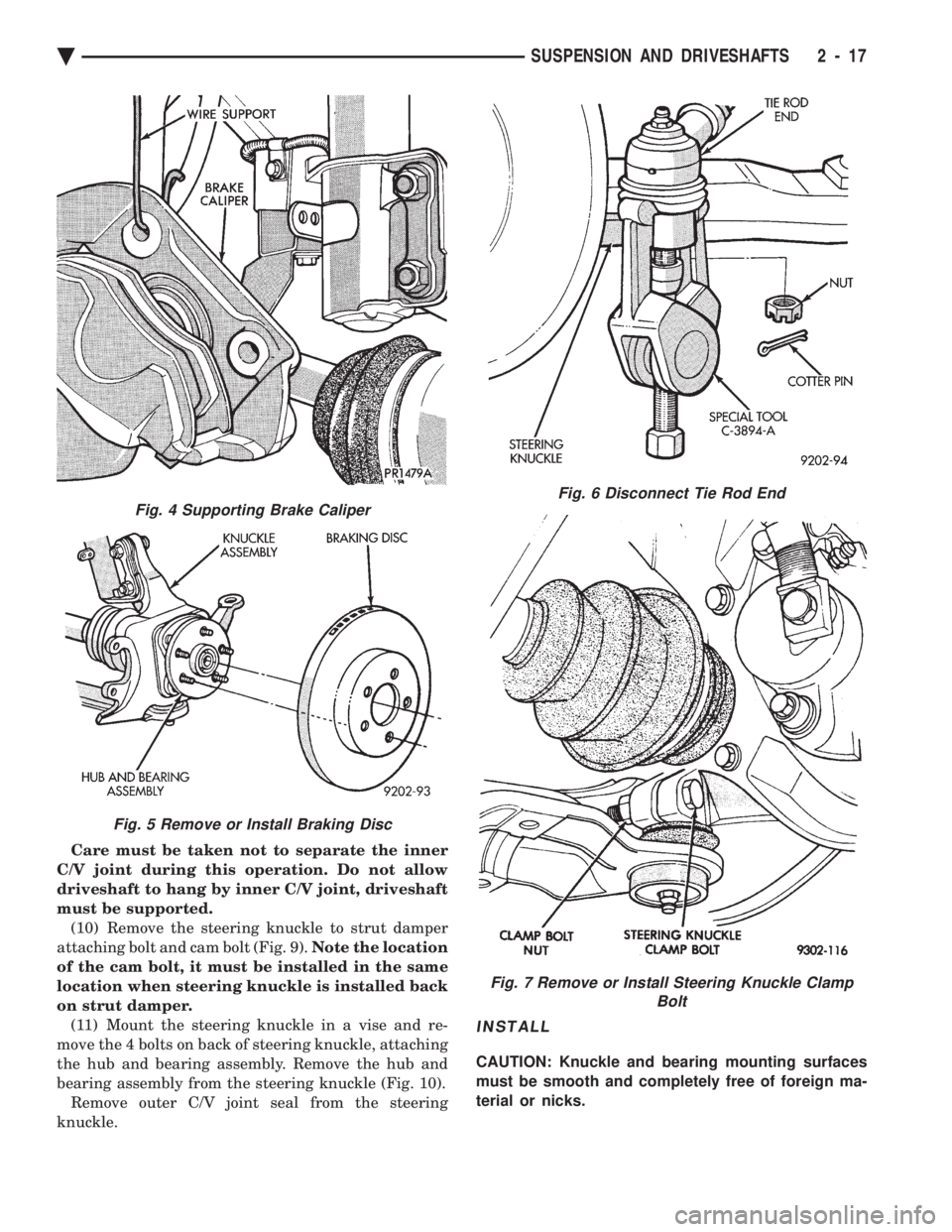
Care must be taken not to separate the inner
C/V joint during this operation. Do not allow
driveshaft to hang by inner C/V joint, driveshaft
must be supported. (10) Remove the steering knuckle to strut damper
attaching bolt and cam bolt (Fig. 9). Note the location
of the cam bolt, it must be installed in the same
location when steering knuckle is installed back
on strut damper. (11) Mount the steering knuckle in a vise and re-
move the 4 bolts on back of steering knuckle, attaching
the hub and bearing assembly. Remove the hub and
bearing assembly from the steering knuckle (Fig. 10). Remove outer C/V joint seal from the steering
knuckle.
INSTALL
CAUTION: Knuckle and bearing mounting surfaces
must be smooth and completely free of foreign ma-
terial or nicks.
Fig. 6 Disconnect Tie Rod End
Fig. 7 Remove or Install Steering Knuckle Clamp Bolt
Fig. 4 Supporting Brake Caliper
Fig. 5 Remove or Install Braking Disc
Ä SUSPENSION AND DRIVESHAFTS 2 - 17