1993 CHEVROLET PLYMOUTH ACCLAIM seat memory
[x] Cancel search: seat memoryPage 722 of 2438
CONDITION: NO MOVEMENT OF BOTH MEMORY MIRRORS OR ONLY ONE MEMORY MIRROR DURING THE RECALL MODE,MEMORY MIRRORS WILL MOVE ONLY WHENTHE POWER MIRROR SWITCH IS ACTUATED.MEMORY SEAT AND RECLINER MOVE INRECALL.
PROCEDURE
(1) Determine the fault precisely. If all memory
mirror recall movements appear to be missing, first
set the mirrors to two different vertical and horizon-
tal positions for both mirrors. Refer to the General
Information paragraph at the beginning of this sec-
tion for position setting instructions. Try to recall
these set positions that were just placed in memory. (2) Observe for no movement in a specific direction
for a specific mirror. If there is still no movement of
either mirror in any direction, re place the control
module. Perform the memory seat diagnostic self
check so the control module will learn the new soft
limits of the assembly. If the non-movement is in a
specific direction or a specific mirror, continue with
the procedure. (3) Perform the diagnostic self tests, mirror check
mode, to determine if the fault is with a motor or
with a position sensing rheostat circuit. Refer to
Memory Seat and Mirror Diagnostic Self-Tests expla-
nation for further information and understanding of
the diagnostic process and identifying of the fault. If
the fault is with a motor, continue this procedure as
follows in step (4) below. If the fault is with a rheo-
stat, as indicated by the mirror nod in the vertical or
horizontal plane, continue the procedure with step (5)
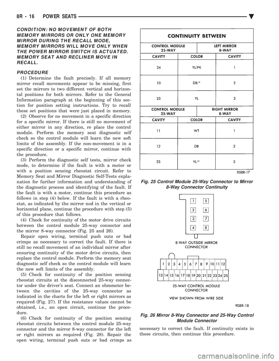
of this procedure that follows. (4) Check for continuity of the motor drive circuits
between the control module 25-way connector and
the mirror 8-way connector (Fig. 25 and 26). Repair open wiring, terminal push outs or bad
crimps as necessary to correct the fault. If there is
still no recall movement of an individual mirror after
ensuring continuity of the motor drive circuits, then
replace the control module. Perform the memory seat
diagnostic self check so the control module will learn
the new soft limits of the assembly. (5) Check for continuity of the position sensing
rheostat circuits at the disconnected 25-way connec-
tor under the driver's seat. Connect an ohmmeter be-
tween the cavities of the 25-way connector as
indicated in the charts for the left or right mirrors as
required (Fig. 27). If the resistance values cannot be
obtained, i.e., an open circuit, continue the proce-
dure. (6) Check for continuity of the position sensing
rheostat circuits between the control module 25-way
connector and the mirror 8-way connector for the left
or right mirrors as required (Fig. 28). Repair the
open wiring, terminal push outs or bad crimps as necessary to correct the fault. If continuity exists in
these circuits, then continue this procedure.
Fig. 25 Control Module 25-Way Connector to Mirror 8-Way Connector Continuity
Fig. 26 Mirror 8-Way Connector and 25-Way Control Module Connector
8R - 16 POWER SEATS Ä
Page 723 of 2438
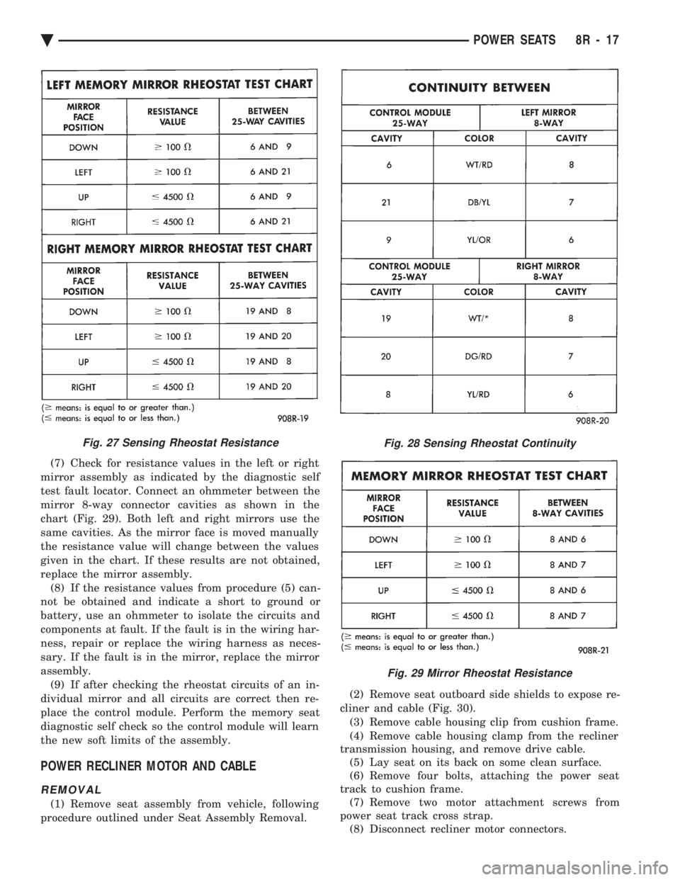
(7) Check for resistance values in the left or right
mirror assembly as indicated by the diagnostic self
test fault locator. Connect an ohmmeter between the
mirror 8-way connector cavities as shown in the
chart (Fig. 29). Both left and right mirrors use the
same cavities. As the mirror face is moved manually
the resistance value will change between the values
given in the chart. If these results are not obtained,
replace the mirror assembly. (8) If the resistance values from procedure (5) can-
not be obtained and indicate a short to ground or
battery, use an ohmmeter to isolate the circuits and
components at fault. If the fault is in the wiring har-
ness, repair or replace the wiring harness as neces-
sary. If the fault is in the mirror, replace the mirror
assembly. (9) If after checking the rheostat circuits of an in-
dividual mirror and all circuits are correct then re-
place the control module. Perform the memory seat
diagnostic self check so the control module will learn
the new soft limits of the assembly.
POWER RECLINER MOTOR AND CABLE
REMOVAL
(1) Remove seat assembly from vehicle, following
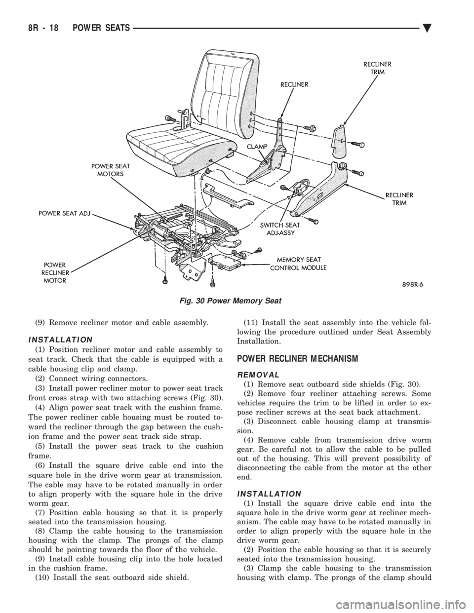
procedure outlined under Seat Assembly Removal. (2) Remove seat outboard side shields to expose re-
cliner and cable (Fig. 30). (3) Remove cable housing clip from cushion frame.
(4) Remove cable housing clamp from the recliner
transmission housing, and remove drive cable. (5) Lay seat on its back on some clean surface.
(6) Remove four bolts, attaching the power seat
track to cushion frame. (7) Remove two motor attachment screws from
power seat track cross strap. (8) Disconnect recliner motor connectors.
Fig. 27 Sensing Rheostat ResistanceFig. 28 Sensing Rheostat Continuity
Fig. 29 Mirror Rheostat Resistance
Ä POWER SEATS 8R - 17
Page 724 of 2438
(9) Remove recliner motor and cable assembly.
INSTALLATION
(1) Position recliner motor and cable assembly to
seat track. Check that the cable is equipped with a
cable housing clip and clamp. (2) Connect wiring connectors.
(3) Install power recliner motor to power seat track
front cross strap with two attaching screws (Fig. 30). (4) Align power seat track with the cushion frame.
The power recliner cable housing must be routed to-
ward the recliner through the gap between the cush-
ion frame and the power seat track side strap. (5) Install the power seat track to the cushion
frame. (6) Install the square drive cable end into the
square hole in the drive worm gear at transmission.
The cable may have to be rotated manually in order
to align properly with the square hole in the drive
worm gear. (7) Position cable housing so that it is properly
seated into the transmission housing. (8) Clamp the cable housing to the transmission
housing with the clamp. The prongs of the clamp
should be pointing towards the floor of the vehicle. (9) Install cable housing clip into the hole located
in the cushion frame. (10) Install the seat outboard side shield. (11) Install the seat assembly into the vehicle fol-
lowing the procedure outlined under Seat Assembly
Installation.
POWER RECLINER MECHANISM
REMOVAL
(1) Remove seat outboard side shields (Fig. 30).
(2) Remove four recliner attaching screws. Some
vehicles require the trim to be lifted in order to ex-
pose recliner screws at the seat back attachment. (3) Disconnect cable housing clamp at transmis-
sion. (4) Remove cable from transmission drive worm
gear. Be careful not to allow the cable to be pulled
out of the housing. This will prevent possibility of
disconnecting the cable from the motor at the other
end.
INSTALLATION
(1) Install the square drive cable end into the
square hole in the drive worm gear at recliner mech-
anism. The cable may have to be rotated manually in
order to align properly with the square hole in the
drive worm gear. (2) Position the cable housing so that it is securely
seated into the transmission housing. (3) Clamp the cable housing to the transmission
housing with clamp. The prongs of the clamp should
Fig. 30 Power Memory Seat
8R - 18 POWER SEATS Ä
Page 725 of 2438
be pointing towards the floor of the vehicle. (4) Install the four recliner to seat frame fasteners
(Fig. 30). (5) Install seat outboard side shields and fix all
trim so that no foam is exposed. (6) Set system soft limits.
MEMORY CONTROL MODULE REPLACEMENT
(1) Remove seat assembly from vehicle and follow the
procedure outlined under Seat Assembly Removal.
(2) Lay seat on its back on a clean surface.
(3) Remove screws attaching control module to
seat track (Fig. 30). (4) Disconnect control module wiring.
(5) Remove control module.
(6) For installation reverse above procedures. Set
system soft limits by performing the memory seat di-
agnostic self check. So that the control module will
learn the soft limits of the assembly.
RECLINER SWITCH REPLACEMENT
(1) Remove seat side shields (Fig. 30).
(2) Disconnect wiring from switch.
(3) Remove attaching screws from side shields.
(4) Remove switch.
(5) For installation reverse above procedures.
RECLINER SWITCH TEST
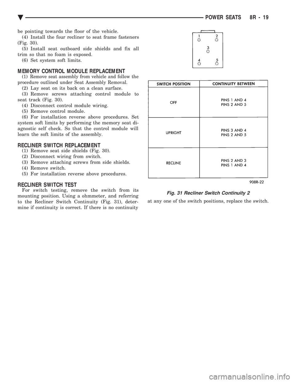
For switch testing, remove the switch from its
mounting position. Using a ohmmeter, and referring
to the Recliner Switch Continuity (Fig. 31), deter-
mine if continuity is correct. If there is no continuity at any one of the switch positions, replace the switch.Fig. 31 Recliner Switch Continuity 2
Ä
POWER SEATS 8R - 19
Page 1067 of 2438
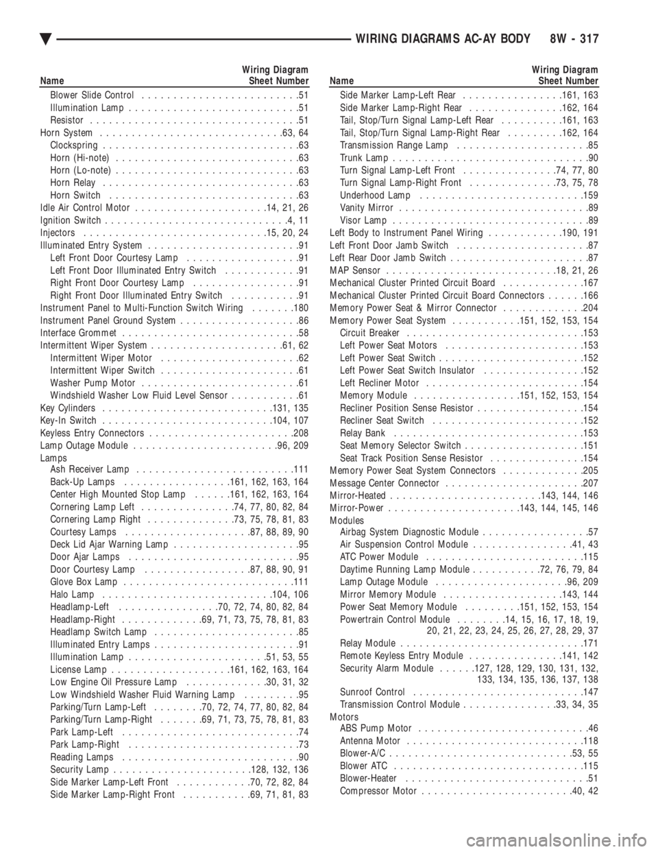
Wiring Diagram
Name Sheet Number
Blower Slide Control .........................51
Illumination Lamp ...........................51
Resistor .................................51
Horn System ............................ .63, 64
Clockspring ...............................63
Horn (Hi-note) .............................63
Horn (Lo-note) .............................63
Horn Relay ...............................63
Horn Switch ..............................63
Idle Air Control Motor .................... .14, 21, 26
Ignition Switch .............................4,11
Injectors ............................ .15, 20, 24
Illuminated Entry System ........................91
Left Front Door Courtesy Lamp ..................91
Left Front Door Illuminated Entry Switch ............91
Right Front Door Courtesy Lamp .................91
Right Front Door Illuminated Entry Switch ...........91
Instrument Panel to Multi-Function Switch Wiring .......180
Instrument Panel Ground System ...................86
Interface Grommet ............................58
Intermittent Wiper System .................... .61, 62
Intermittent Wiper Motor ......................62
Intermittent Wiper Switch ......................61
Washer Pump Motor .........................61
Windshield Washer Low Fluid Level Sensor ...........61
Key Cylinders .......................... .131, 135
Key-In Switch .......................... .104, 107
Keyless Entry Connectors ...................... .208
Lamp Outage Module ...................... .96, 209
Lamps Ash Receiver Lamp ........................ .111
Back-Up Lamps ................ .161, 162, 163, 164
Center High Mounted Stop Lamp ......161, 162, 163, 164
Cornering Lamp Left ...............74, 77, 80, 82, 84
Cornering Lamp Right ..............73, 75, 78, 81, 83
Courtesy Lamps ................... .87, 88, 89, 90
Deck Lid Ajar Warning Lamp ....................95
Door Ajar Lamps ...........................95
Door Courtesy Lamp ................ .87, 88, 90, 91
Glove Box Lamp .......................... .111
Halo Lamp .......................... .104, 106
Headlamp-Left ............... .70, 72, 74, 80, 82, 84
Headlamp-Right ............ .69, 71, 73, 75, 78, 81, 83
Headlamp Switch Lamp .......................85
Illuminated Entry Lamps .......................91
Illumination Lamp ..................... .51, 53, 55
License Lamp .................. .161, 162, 163, 164
Low Engine Oil Pressure Lamp .............30, 31, 32
Low Windshield Washer Fluid Warning Lamp .........95
Parking/Turn Lamp-Left ........70, 72, 74, 77, 80, 82, 84
Parking/Turn Lamp-Right .......69, 71, 73, 75, 78, 81, 83
Park Lamp-Left ............................74
Park Lamp-Right ...........................73
Reading Lamps ............................90
Security Lamp ..................... .128, 132, 136
Side Marker Lamp-Left Front ............70, 72, 82, 84
Side Marker Lamp-Right Front ...........69, 71, 81, 83Wiring Diagram
Name Sheet Number
Side Marker Lamp-Left Rear ................161, 163
Side Marker Lamp-Right Rear ...............162, 164
Tail, Stop/Turn Signal Lamp-Left Rear ..........161, 163
Tail, Stop/Turn Signal Lamp-Right Rear .........162, 164
Transmission Range Lamp .....................85
Trunk Lamp ...............................90
Turn Signal Lamp-Left Front ...............74, 77, 80
Turn Signal Lamp-Right Front ..............73, 75, 78
Underhood Lamp ......................... .159
Vanity Mirror ..............................89
Visor Lamp ...............................89
Left Body to Instrument Panel Wiring ............190, 191
Left Front Door Jamb Switch .....................87
Left Rear Door Jamb Switch ......................87
MAP Sensor .......................... .18, 21, 26
Mechanical Cluster Printed Circuit Board .............167
Mechanical Cluster Printed Circuit Board Connectors ......166
Memory Power Seat & Mirror Connector .............204
Memory Power Seat System ...........151, 152, 153, 154
Circuit Breaker ........................... .153
Left Power Seat Motors ..................... .153
Left Power Seat Switch ...................... .152
Left Power Seat Switch Insulator ................152
Left Recliner Motor ........................ .154
Memory Module ................ .151, 152, 153, 154
Recliner Position Sense Resistor .................154
Recliner Seat Switch ....................... .152
Relay Bank ............................. .153
Seat Memory Selector Switch ...................151
Seat Track Position Sense Resistor ...............154
Memory Power Seat System Connectors .............205
Message Center Connector ..................... .207
Mirror-Heated ....................... .143, 144, 146
Mirror-Power .................... .143, 144, 145, 146
Modules Airbag System Diagnostic Module .................57
Air Suspension Control Module ................41, 43
ATC Power Module ........................ .115
Daytime Running Lamp Module ...........72, 76, 79, 84
Lamp Outage Module .................... .96, 209
Mirror Memory Module .................. .143, 144
Power Seat Memory Module .........151, 152, 153, 154
Powertrain Control Module ........14, 15, 16, 17, 18, 19,
20, 21, 22, 23, 24, 25, 26, 27, 28, 29, 37
Relay Module ............................ .171
Remote Keyless Entry Module ...............141, 142
Security Alarm Module ......127, 128, 129, 130, 131, 132,
133, 134, 135, 136, 137, 138
Sunroof Control .......................... .147
Transmission Control Module ...............33, 34, 35
Motors ABS Pump Motor ...........................46
Antenna Motor ........................... .118
Blower-A/C ............................ .53, 55
Blower ATC ............................. .115
Blower-Heater .............................51
Compressor Motor ....................... .40, 42
Ä WIRING DIAGRAMS AC-AY BODY 8W - 317
Page 1068 of 2438
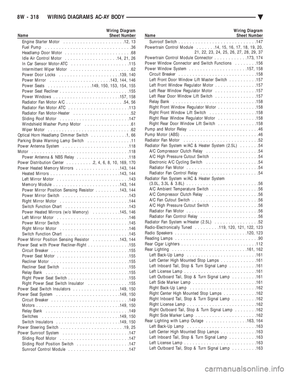
Wiring Diagram
Name Sheet Number
Engine Starter Motor ..................... .12, 13
Fuel Pump ...............................36
Headlamp Door Motor ........................68
Idle Air Control Motor .................. .14, 21, 26
In Car Sensor Motor-ATC .................... .115
Intermittent Wiper Motor ......................62
Power Door Locks ..................... .139, 140
Power Mirror ..................... .143, 144, 146
Power Seats ............... .149, 150, 153, 154, 155
Power Seat Recliner ........................ .155
Power Windows ....................... .157, 158
Radiator Fan Motor A/C .................... .54, 56
Radiator Fan Motor ATC ..................... .113
Radiator Fan Motor-Heater .....................52
Sliding Roof Motor ........................ .147
Windshield Washer Pump Motor .................61
Wiper Motor ..............................62
Optical Horn Headlamp Dimmer Switch .............1,66
Parking Brake Warning Lamp Switch ................11
Power Antenna System ....................... .118
Motor .................................. .118
Power Antenna & NBS Relay ...................118
Power Distribution Center ..........2,4,6,8,10, 169, 170
Power Heated Memory Mirrors ................143, 144
Heated Mirror s........................ .143, 144
Left Mirror Motor ......................... .143
Memory Module ....................... .143, 144
Power Mirror Position Sensing Resistor .........143, 144
Power Mirror Switch ....................... .143
Right Mirror Motor ........................ .144
Switch Function Chart ...................... .143
Power Heated Mirrors (w/o Memory) ..........145, 146
Left Mirror Motor ......................... .146
Power Mirror Switch ....................... .145
Right Mirror Motor ........................ .146
Switch Function Chart ...................... .145
Power Mirror Position Sensing Resistor ..........143, 144
Power Seat with Power Recliner-Right ...............155
Circuit Breaker ........................... .155
Power Seat Motor ......................... .155
Recliner Motor ........................... .155
Recliner Seat Switch ....................... .155
Relay Bank ............................. .155
Right Power Seat Switch ..................... .155
Right Power Seat Switch Insulator ...............155
Power Seat Switch Insulators .................149, 150
Power Seat System ...................... .149, 150
Circuit Breaker ........................... .149
Motors ............................. .149, 150
Relay Bank ............................. .149
Switches ........................... .149, 150
Switch Insulators ...................... .149, 150
Power Steering Switch ...................... .19, 25
Power Sunroof System ....................... .147
Sliding Roof Motor ........................ .147
Sliding Roof Position Switch ...................147
Sunroof Control Module ..................... .147Wiring Diagram
Name Sheet Number
Sunroof Switch ........................... .147
Powertrain Control Module .......14, 15, 16, 17, 18, 19, 20,
21, 22, 23, 24, 25, 26, 27, 28, 29, 37
Powertrain Control Module Connector ............173, 174
Power Window Connector and Switch Functions ........156
Power Window System .................... .157, 158
Circuit Breaker ........................... .158
Left Front Door Window Lift Master Switch ..........157
Left Front Window Regulator Motor ...............157
Left Rear Window Regulator Motor ...............157
Left Rear Door Window Lift Switch ...............157
Relay Bank ............................. .158
Right Front Window Regulator Motor ..............158
Right Front Window Lift Switch .................158
Right Rear Window Regulator Motor ..............158
Right Rear Door Window Lift Switch ..............158
Pump and Motor Relay .........................46
Pump Motor (ABS) ............................46
Radiator Fan Motor ...........................52
Radiator Fan System w/AC & Heater System (2.5L) .......54
A/C Compressor Clutch Relay ...................54
A/C High Pressure Cutout Switch .................54
Electronic A/C Cycling Switch ...................54
Radiator Fan Motor ..........................54
Radiator Fan Control Relay .....................54
Radiator Fan System w/AC & Heater System (3.0L, 3.3L & 3.8L) ..........................56
A/C Ambient Temperature Switch .................56
A/C Compressor Clutch Relay ...................56
A/C Fan Cutout Switch ........................56
A/C High Pressure Cutout Switch .................56
Radiator Fan Motor ..........................56
Radiator Fan Control Relay .....................56
Radiator Fan System w/Heater (2.5L) ................52
Radio-Electronically Tuned .........119, 120, 121, 122, 123
Radio Speakers ......................... .120, 123
Reading Lamps ..............................90
Rear Cigar Lighters .......................... .112
Rear Lighting .......................... .161, 162
Left Back-Up Lamp ........................ .161
Left Center High Mounted Stop Lamps .............161
Left Inboard Tail, Stop & Turn Signal Lamp ..........161
Left License Lamp ......................... .161
Left Outboard Tail, Stop & Turn Signal Lamp .........161
Left Side Marker Lamp ...................... .161
Right Back-Up Lamp ....................... .162
Right Center High Mounted Stop Lamps ............162
Right Inboard Tail, Stop & Turn Signal Lamp .........162
Right License Lamp ........................ .162
Right Outboard Tail, Stop & Turn Signal Lamp ........162
Right Side Marker Lamp ..................... .162
Rear Lighting with Lamp Outage ...............163, 164
Left Back-Up Lamp ........................ .163
Left Center High Mounted Stop Lamps .............163
Left Inboard Tail, Stop & Turn Signal Lamp ..........163
Left License Lamp ......................... .163
Left Outboard Tail, Stop & Turn Signal Lamp .........163
8W - 318 WIRING DIAGRAMS AC-AY BODY Ä
Page 1071 of 2438
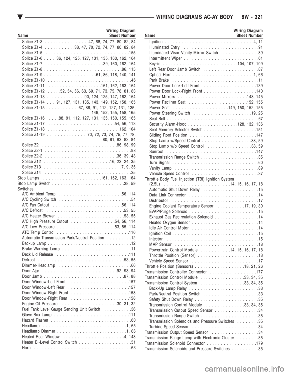
Wiring Diagram
Name Sheet Number
Splice Z1-3 ............... .47, 68, 74, 77, 80, 82, 84
Splice Z1-4 .......... .38, 47, 70, 72, 74, 77, 80, 82, 84
Splice Z1-5 ............................. .155
Splice Z1-6 .....36, 124, 125, 127, 131, 135, 160, 162, 164
Splice Z1-7 .................... .39, 160, 162, 164
Splice Z1-8 ........................... .86, 115
Splice Z1-9 .................. .61, 86, 118, 140, 141
Splice Z1-10 ..............................46
Splice Z1-11 .................. .161, 162, 163, 164
Splice Z1-12 .....52, 54, 56, 63, 69, 71, 73, 75, 78, 81, 83
Splice Z1-13 ............. .90, 124, 125, 147, 162, 164
Splice Z1-14 . . . .91, 127, 131, 135, 143, 149, 152, 158, 165
Splice Z1-15 ........... .67, 88, 91, 112, 127, 131, 135,
149, 152, 155, 158, 165
Splice Z1-16 .....88, 91, 112, 127, 131, 135, 150, 155, 165
Splice Z1-17 ....................... .54, 56, 113
Splice Z1-18 ......................... .162, 164
Splice Z1-19 .............. .70, 72, 73, 74, 75, 77, 78,
80, 81, 82, 83, 84
Splice Z2 .......................... .86, 98, 99
Splice Z2-1 ...............................98
Splice Z2-2 ......................... .36, 39, 43
Splice Z12 ....................... .16, 22, 24, 35
Splice Z13 ............................7,9,35
Splice Z14 ...............................35
Stop Lamps .................... .161, 162, 163, 164
Stop Lamp Switch ......................... .38, 59
Switches A/C Ambient Temp ...................... .56, 114
A/C Cycling Switch ..........................54
A/C Fan Cutout ........................ .56, 114
A/C Defrost ........................... .53, 55
A/C Heater Blower ....................... .53, 55
A/C High Pressure Cutout ................54, 56, 114
A/C Low Pressure .................... .53, 55, 114
ATC Temp Control ......................... .116
Automatic Transmission Park/Neutral Position .........12
Backup Lamp ..............................12
Brake Warning Lamp .........................11
Deck Lid Release ......................... .111
Defrost .............................. .53, 55
Dimmer-Headlamp ..........................66
Door Ajar .......................... .92, 93, 94
Door Jamb ............................ .87, 88
Door Window-Left Front ..................... .157
Door Window-Left Rear ..................... .157
Door Window-Right Front .................... .158
Door Window-Right Rear .................... .158
Engine Oil Pressure .................... .30, 31, 32
Fuel Tank Level Gauge Sending Unit Switch ..........36
Glove Box Lamp .......................... .111
Hazard Flasher .............................60
Headlamp ..............................1,65
Headlamp Dimmer .........................1,66
Heated Rear Window ......................4,148
Heater Bi-Level Control Switch ...................51
Horn ...................................63Wiring Diagram
Name Sheet Number
Ignition ................................4,11
Illuminated Entry ...........................91
Illuminated Visor Vanity Mirror Switch ..............89
Intermittent Wiper ...........................61
Key-in .......................... .104, 107, 109
Left Rear Door Jamb Switch ....................87
Optical Horn .............................1,66
Park Brake ...............................11
Power Door Lock-Left Front ................... .139
Power Door Lock-Right Front ...................140
Power Mirrors ........................ .143, 145
Power Recliner Seat .................... .152, 155
Power Seat ................... .149, 150, 152, 155
Power Steering Switch .................... .19, 25
Seat Belt .................................67
Security Alarm-Hood ................. .128, 132, 136
Seat Memory Selector Switch ...................151
Sliding Roof Position ....................... .147
Stop Lamp w/Speed Control ..................38, 59
Stop Lamp w/o Speed Control ................38, 59
Sunroof ............................... .147
Transmission Range Switch .....................35
Turn Signal ...............................60
Vanity Lamp ..............................89
Vehicle Speed Control ........................37
Throttle Body Fuel Injection (TBI) Ignition System (2.5L) ....................... .14, 15, 16, 17, 18
Automatic Shut Down Relay ....................15
Data Link Connector .........................14
Distributor ...............................17
Engine Coolant Temperature Sensor ..........17, 19, 30
EVAP/Purge Solenoid .........................15
Exhaust Gas Recirculation Solenoid ................14
Heated Oxygen Sensor ........................14
Idle Air Control Motor ........................14
Ignition Coil ...............................15
Injector .................................15
MAP Sensor ..............................18
Powertrain Control Module ...........14, 15, 16, 17, 18
Throttle Position (Sensor) ......................18
Vehicle Speed Sensor ........................17
Throttle Position (Sensors) ..................18, 21, 26
Transmission Controller Connector .................177
Transmission Control Module ................33, 34, 35
Transmission Control System ................33, 34, 35
Back-Up Lamp Relay .........................33
Park/Neutral Position Switch ....................33
Safety Shut Down Relay .......................35
Transmission Control Module ...............33, 34, 35
Transmission Output Speed Sensor ................34
Transmission Range Switch .....................35
Transmission Solenoids and Pressure Switches ........35
Turbine Speed Sensor ........................34
Transmission Output Speed Sensor .................34
Transmission Range Lamp with Electronic Cluster ........85
Transmission Solenoid Connector ..................179
Transmission Solenoids and Pressure Switches ..........35
Ä WIRING DIAGRAMS AC-AY BODY 8W - 321