1993 CHEVROLET PLYMOUTH ACCLAIM fuel type
[x] Cancel search: fuel typePage 1742 of 2438
with a minimum octane of 87 may be used. However,
the use of lower octane gasoline will result in re-
duced performance.
FLEXIBLE FUEL AA-BODY VEHICLES
These vehicles will operate on either unleaded gas-
oline with a minimum posted octane of 87 or M85
fuel. M85 fuel is a mixture of 85 percent methanol
and 15 percent unleaded gasoline. The vehicle also
will operate on mixture of M85 and unleaded gaso-
line with a minimum posted octane of 87. Do not
use 100 percent methanol in these vehicles.
THE FOLLOWING IS APPLICABLE TO ALL VEHICLES
Light spark knock at low engine speeds is not
harmful to your engine. However, continued heavy
spark knock at high speeds can cause damage and
should be reported to your dealer immediately. En-
gine damage resulting from operating with a heavy
spark knock may not be covered by the new vehicle
warranty. In addition to using unleaded gasoline with the
proper octane rating, gasolines that contain deter-
gents, corrosion and stability additives are recom-
mended. Using gasolines that have these additives
will help improve fuel economy, reduce emissions,
and maintain vehicle performance. Generally, pre-
mium unleaded gasolines contain more additive than
regular unleaded. Poor quality gasoline can cause problems such as
hard starting, stalling, and stumble. If you experi-
ence these problems, try another brand of gasoline
before considering service for the vehicle.
GASOLINE/OXYGENATE BLENDS
Some fuel suppliers blend gasoline with materials
that contain oxygen such as alcohol, MTBE (Methyl
Tertiary Butyl Ether) and ETBE (Ethyl Tertiary Bu-
tyl Ether). The type and amount of oxygenate used
in the blend is important. The following are generally used in gasoline
blends: Ethanol - (Ethyl or Grain Alcohol) properly blended, is used as a mixture of 10 percent ethanol
and 90 percent gasoline. Gasoline blended with eth-
anol may be used in your vehicle. Methanol - (Methyl or Wood Alcohol) is used in a
variety of concentrations when blended with un-
leaded gasoline. You may find fuels containing 3 per-
cent or more methanol along with other alcohols
called cosolvents. Do not use gasolines containing Methanol.
Use of methanol/gasoline blends may result in
starting and driveability problems and damage criti-
cal fuel system components. Problems that are the result of using methanol/gas-
oline blends are not the responsibility of Chrysler
Motors and may not be covered by the new vehicle
warranty. MTBE/ETBE - Gasoline and MTBE (Methyl Ter-
tiary Butyl Ether) blends are a mixture of unleaded
gasoline blended and up to 15 percent MTBE. Gaso-
line and ETBE (Ethyl Tertiary Butly Ether) are
blends of gasoline and up to 17 percent ETBE. Gas-
oline blended with MTBE or ETBE may be used in
your vehicle. Clean Air Gasoline
Many gasolines are now being blended that con-
tribute to cleaner air, especially in those areas of the
country where pollution levels are high. These new
blends provide a cleaner burning fuel and some are
referred to as reformulated gasoline. In areas of the country where carbon monoxide lev-
els are high, gasolines are being treated with oxy-
genated materials such as ETBE, MTBE and
ethanol. The use of gasoline blended with these ma-
terials also contributes to cleaner air. Chrysler Corporation supports these efforts toward
cleaner air and recommends that you use these gas-
olines as they become available. Materials Added to Fuel
Indiscriminate use of fuel system cleaning agents
should be avoided. Many of these materials intended
for gum and varnish removal may contain active sol-
vents of similar ingredients that can be harmful to
fuel system gasket and diaphragm materials.
14 - 2 FUEL SYSTEMS Ä
Page 1750 of 2438
REMOVAL
(1) Perform the Fuel System Pressure Release pro-
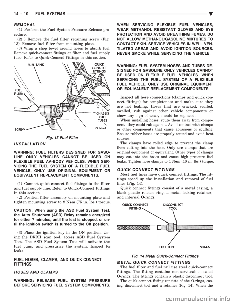
cedure. (2) ) Remove the fuel filter retaining screw (Fig.
13). Remove fuel filter from mounting plate.
(3) Wrap a shop towel around hoses to absorb fuel.
Remove quick-connect fittings at filter and fuel supply
tube. Refer to Quick-Connect Fittings in this section.
INSTALLATION
WARNING: FUEL FILTERS DESIGNED FOR GASO-
LINE ONLY VEHICLES CANNOT BE USED ON
FLEXIBLE FUEL AA-BODY VEHICLES. WHEN SER-
VICING THE FUEL SYSTEM OF A FLEXIBLE FUEL
VEHICLE, ONLY USE ORIGINAL EQUIPMENT OR
EQUIVALENT REPLACEMENT COMPONENTS.
(1) Connect quick-connect fuel fittings to the filter
and fuel supply line. Refer to Quick-Connect Fittings
in this section. (2) Position filter assembly on mounting plate and
tighten mounting screw to 8 N Im (75 in. lbs.) torque.
CAUTION: When using the ASD Fuel System Test,
the Auto Shutdown (ASD) Relay remains energized
for either 7 minutes, until the test is stopped, or un-
til the ignition switch is turned to the Off position.
(3) Place the ignition key in the ON position. Us-
ing the DRBII scan tool, access ASD Fuel System
Test. The ASD Fuel System Test will activate the
fuel pump and pressurize the system. Inspect for
leaks.
FUEL HOSES, CLAMPS, AND QUICK CONNECT
FITTINGS
HOSES AND CLAMPS
WARNING: RELEASE FUEL SYSTEM PRESSURE
BEFORE SERVICING FUEL SYSTEM COMPONENTS. WHEN SERVICING FLEXIBLE FUEL VEHICLES,
WEAR METHANOL RESISTANT GLOVES AND EYE
PROTECTION AND AVOID BREATHING FUMES. DO
NOT ALLOW METHANOL/GASOLINE MIXTURES TO
CONTACT SKIN. SERVICE VEHICLES IN WELL VEN-
TILATED AREAS AND AVOID IGNITION SOURCES.
NEVER SMOKE WHILE SERVICING THE VEHICLE.
WARNING: FUEL SYSTEM HOSES AND TUBES DE-
SIGNED FOR GASOLINE ONLY VEHICLES CANNOT
BE USED ON FLEXIBLE FUEL VEHICLES. WHEN
SERVICING THE FUEL SYSTEM OF A FLEXIBLE
FUEL VEHICLE, ONLY USE ORIGINAL EQUIPMENT
OR EQUIVALENT REPLACEMENT COMPONENTS.
Inspect all hose connections (clamps and quick con-
nect fittings) for completeness and make sure they
are not leaking. Hoses that are cracked, scuffed,
swelled, rub against other vehicle components or
show any sign of wear, should be replaced.
When installing hoses, route them away from compo-
nents they could rub against. Avoid contact with clamps
or other components that cause abrasions or scuffing.
Ensure rubber hoses are properly routed and avoid heat
sources. The clamps have rolled edge to prevent the clamp
from cutting into the hose. Only use clamps that are
original equipment or equivalent. Other types of clamps
may cut into the hoses and cause high pressure fuel
leaks. Tighten hose clamps to 1 N Im (10 in. lbs.) torque.
QUICK CONNECT FITTINGS
Most fuel lines have quick connect fittings. The fit-
tings speed up the installation and removal of fuel
lines (Fig. 14). Quick connect fittings consist of a metal casing, a
black plastic release ring, a metal locking retainer,
and internal O-rings.
METAL QUICK CONNECT FITTINGS
The fuel filter and fuel rail use steel quick-connect
fittings. The fitting contains non-serviceable sealed
O-rings. The fittings contain a plastic disconnect tool.
The quick-connect fitting consists of the O-rings, cas-
ing, disconnect tool and a retainer (Fig. 14). When the
Fig. 13 Fuel Filter
Fig. 14 Metal Quick-Connect Fittings
14 - 10 FUEL SYSTEMS Ä
Page 1751 of 2438
fuel tube enters the fitting, the retainer locks the shoul-
der of the nipple in place and the O-rings seal the tube.
CAUTION: Quick-connect fittings are not serviced
separately. Do not attempt to repair damaged quick-
connect fittings or fuel tubes. Replace the complete
fuel tube/quick-connect fitting assembly.
When installing fuel tubes, route them in the holders
along the frame rail, fuel tank and the rear of the en-
gine.
REMOVAL
WARNING: RELEASE FUEL SYSTEM PRESSURE
BEFORE SERVICING FUEL SYSTEM COMPONENTS.
WHEN SERVICING FLEXIBLE FUEL VEHICLES,
WEAR METHANOL RESISTANT GLOVES AND EYE
PROTECTION AND AVOID BREATHING FUMES. DO
NOT ALLOW METHANOL/GASOLINE MIXTURES TO
CONTACT SKIN. SERVICE VEHICLES IN WELL VEN-
TILATED AREAS AND AVOID IGNITION SOURCES.
NEVER SMOKE WHILE SERVICING THE VEHICLE.
(1) Disconnect negative cable from the battery.
(2) Perform the Fuel Pressure Release Procedure.
Refer to the Fuel Pressure Release Procedure in this
section. (3) Remove any loose dirt from quick connect fit-
tings.
WARNING: WRAP SHOP TOWELS AROUND HOSES
TO CATCH ANY FUEL SPILLAGE.
(4) Push the quick connect fitting toward the fuel
tube while depressing the built-in release tool. Then
slightly twist the fitting and pull it off the fuel tube
(Fig. 14). (5) Cover the fitting to prevent contamination.
TUBE/FITTING SERVICE
WARNING: RELEASE FUEL SYSTEM PRESSURE
BEFORE SERVICING FUEL SYSTEM COMPONENTS.
WHEN SERVICING FLEXIBLE FUEL VEHICLES,
WEAR METHANOL RESISTANT GLOVES AND EYE
PROTECTION AND AVOID BREATHING FUMES. DO
NOT ALLOW METHANOL/GASOLINE MIXTURES TO
CONTACT SKIN. SERVICE VEHICLES IN WELL VEN-
TILATED AREAS AND AVOID IGNITION SOURCES.
NEVER SMOKE WHILE SERVICING THE VEHICLE.
If a quick connect fitting needs service, the follow-
ing procedure must be followed: (1) Disconnect the battery negative battery cable.
(2) Perform the Fuel System Pressure Release Pro-
cedure.
WARNING: WRAP SHOP TOWELS AROUND HOSES
TO CATCH ANY FUEL SPILLAGE. (3) Remove the quick connect fitting from the fuel
tube by pushing in on the plastic ring located on the
end of the fitting. Gently pull the fitting from the
fuel tube. (4) Cut off the crimp ferrules at each end of the
hose, taking care not to damage the quick connect
fitting or the fuel tube. (5) Discard the ferrules and hose.
WARNING: FUEL SYSTEM HOSES AND TUBES DE-
SIGNED FOR GASOLINE ONLY VEHICLES CANNOT
BE USED ON FLEXIBLE FUEL VEHICLES. WHEN
SERVICING THE FUEL SYSTEM OF A FLEXIBLE
FUEL VEHICLE, ONLY USE ORIGINAL EQUIPMENT
OR EQUIVALENT REPLACEMENT COMPONENTS.
(6) Replace the hose using original equipment or
equivalent hose. (7) Attach the replacement hose to the quick con-
nect fitting and fuel tube using the correct hose
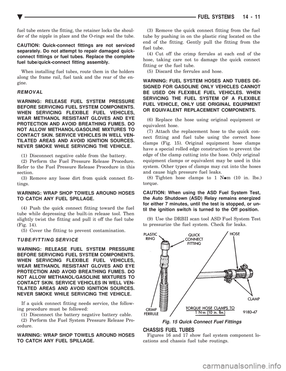
clamps (Fig. 15). Original equipment hose clamps
have a special rolled edge construction to prevent the
edge of the clamp cutting into the hose. Only original
equipment clamps or equivalent may be used in this
system. Other types of clamps may cut into the hoses
and cause high pressure fuel leaks. (8) Tighten hose clamps to 1 N Im (10 in. lbs.)
torque.
CAUTION: When using the ASD Fuel System Test,
the Auto Shutdown (ASD) Relay remains energized
for either 7 minutes, until the test is stopped, or un-
til the ignition switch is turned to the Off position.
(9) Use the DRBII scan tool ASD Fuel System Test
to pressurize the fuel system. Check for leaks.
CHASSIS FUEL TUBES
Figures 16 and 17 show fuel system component lo-
cations and chassis fuel tube routings.
Fig. 15 Quick Connect Fuel Fittings
Ä FUEL SYSTEMS 14 - 11
Page 1788 of 2438
2.2L/2.5L SINGLE POINT FUEL INJECTIONÐSERVICE PROCEDURES INDEX
page page
Canister Purge Solenoid ................... 53
Electric Exhaust Gas Recirculation Transducer (EET) Service ............................... 53
Fuel Fitting ............................. 50
Fuel Injector ............................ 51
Fuel Lines and Hoses ..................... 48
Fuel Pressure Regulator ................... 51 Fuel System Pressure Release Procedure
...... 48
Heated Oxygen Sensor (O
2Sensor) .......... 54
Idle Air Control Motor ..................... 53
Manifold Absolute Pressure Sensor ........... 53
PCM Service ............................ 54
Throttle Body ............................ 48
Throttle Position Sensor ................... 52
FUEL LINES AND HOSES
Perform the Fuel System Pressure Relief Procedure
before servicing the fuel system. The procedure must
be done to bleed fuel pressure from the system before
removing clamps or hoses. Use care when removing fuel hoses to prevent dam-
age to hose or hose nipple. Always use new hose
clamps, of the correct type, during reassembly. Tighten
hose clamps to 1 N Im (10 in. lbs.) torque. Do not use
aviation style clamps on this system or hose
damage may result.
FUEL SYSTEM PRESSURE RELEASE PROCEDURE
CAUTION: Before servicing the fuel pump, fuel lines,
fuel filter, throttle body, or fuel injector, release fuel
system pressure.
(1) Loosen fuel filler cap to release fuel tank pres-
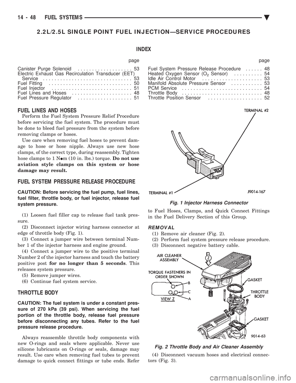
sure. (2) Disconnect injector wiring harness connector at
edge of throttle body (Fig. 1). (3) Connect a jumper wire between terminal Num-
ber 1 of the injector harness and engine ground. (4) Connect a jumper wire to the positive terminal
Number 2 of the injector harness and touch the battery
positive post for no longer than 5 seconds . This
releases system pressure. (5) Remove jumper wires.
(6) Continue fuel system service.
THROTTLE BODY
CAUTION: The fuel system is under a constant pres-
sure of 270 kPa (39 psi). When servicing the fuel
portion of the throttle body, release fuel pressure
before disconnecting any tubes. Refer to the fuel
pressure release procedure.
Always reassemble throttle body components with
new O-rings and seals where applicable. Never use
silicone lubricants on O-rings or seals, damage may
result. Use care when removing fuel tubes to prevent
damage to quick connect fittings or tube ends. Refer to Fuel Hoses, Clamps, and Quick Connect Fittings
in the Fuel Delivery Section of this Group.
REMOVAL
(1) Remove air cleaner (Fig. 2).
(2) Perform fuel system pressure release procedure.
(3) Disconnect negative battery cable.
(4) Disconnect vacuum hoses and electrical connec-
tors (Fig. 3).
Fig. 1 Injector Harness Connector
Fig. 2 Throttle Body and Air Cleaner Assembly
14 - 48 FUEL SYSTEMS Ä
Page 2150 of 2438
PRESSURE GAUGES
High quality dial type air pressure gauges are rec-
ommended. After checking pressure with the gauge,
replace valve caps and tighten finger tight.
TIRE INFLATION PRESSURES
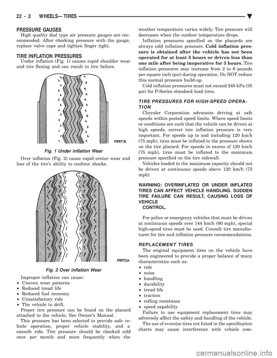
Under inflation (Fig. 1) causes rapid shoulder wear
and tire flexing and can result in tire failure.
Over inflation (Fig. 2) cause rapid center wear and
loss of the tire's ability to cushion shocks.
Improper inflation can cause:
² Uneven wear patterns
² Reduced tread life
² Reduced fuel economy
² Unsatisfactory ride
² The vehicle to drift.
Proper tire pressure can be found on the placard
attached to the vehicle, See Owner's Manual. This pressure has been selected to provide safe ve-
hicle operation, proper vehicle stability, and a
smooth ride. Tire pressure should be checked cold
once per month and more frequently when the weather temperature varies widely. Tire pressure will
decreases when the outdoor temperature drops.
Inflation pressures specified on the placards are
always cold inflation pressure. Cold inflation pres-
sure is obtained after the vehicle has not been
operated for at least 3 hours or driven less than
one mile after being inoperative for 3 hours. Tire
inflation pressures may increase from 2 to 6 pounds
per square inch (psi) during operation. Do NOT reduce
this normal pressure build-up. Cold inflation pressures must not exceed 240 kPa (35
psi) for P-Series standard load tires.
TIRE PRESSURES FOR HIGH-SPEED OPERA- TION
Chrysler Corporation advocates driving at safe
speeds within posted speed limits. Where speed limits
or conditions are such that the vehicle can be driven at
high speeds, correct tire inflation pressure is very
important. For speeds up to and including 120 km/h
(75 mph), tires must be inflated to the pressure shown
on the tire placard. For speeds in excess of 120 km/h
(75 mph), tires must be inflated to the maximum
pressure specified on the tire sidewall. Vehicles loaded to the maximum capacity should not
be driven at continuous speeds above 120 km/h (75
mph).
WARNING: OVERINFLATED OR UNDER INFLATED
TIRES CAN AFFECT VEHICLE HANDLING. SUDDEN
TIRE FAILURE CAN RESULT, CAUSING LOSS OF
VEHICLE CONTROL.
For police or emergency vehicles that must be driven
at continuous speeds over 144 km/h (90 mph), special
high-speed tires must be used. Consult tire manufac-
turer for tire and inflation pressure recommendations.
REPLACEMENT TIRES
The original equipment tires on the vehicle have
been engineered to provide a proper balance of many
characteristics such as:
² ride
² noise
² handling
² durability
² tread life
² traction
² rolling resistance
² speed capability
Failure to use equipment replacement tires may
adversely affect the safety and handling of the vehicle. The use of oversize tires not listed in the specification
charts may cause interference with vehicle com-
Fig. 1 Under inflation Wear
Fig. 2 Over inflation Wear
22 - 2 WHEELSÐTIRES Ä
Page 2408 of 2438
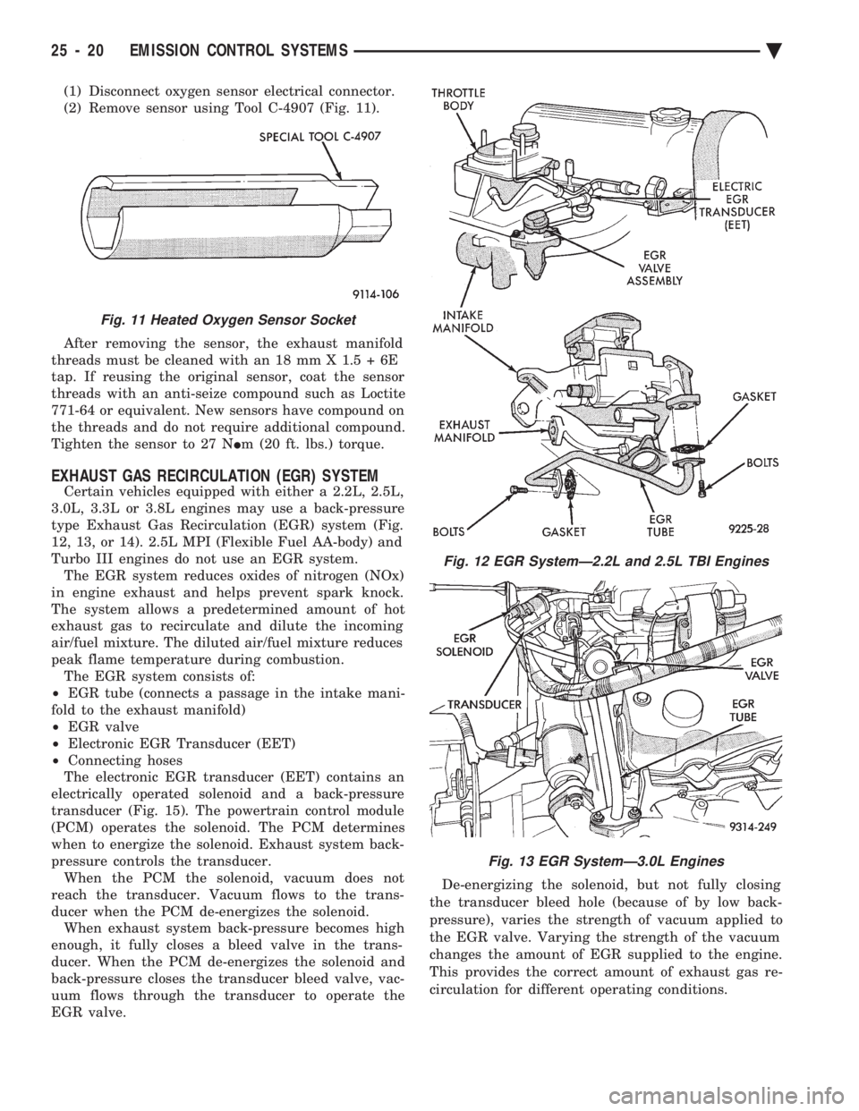
(1) Disconnect oxygen sensor electrical connector.
(2) Remove sensor using Tool C-4907 (Fig. 11).
After removing the sensor, the exhaust manifold
threads must be cleaned with an 18 mm X 1.5 + 6E
tap. If reusing the original sensor, coat the sensor
threads with an anti-seize compound such as Loctite
771-64 or equivalent. New sensors have compound on
the threads and do not require additional compound.
Tighten the sensor to 27 N Im (20 ft. lbs.) torque.
EXHAUST GAS RECIRCULATION (EGR) SYSTEM
Certain vehicles equipped with either a 2.2L, 2.5L,
3.0L, 3.3L or 3.8L engines may use a back-pressure
type Exhaust Gas Recirculation (EGR) system (Fig.
12, 13, or 14). 2.5L MPI (Flexible Fuel AA-body) and
Turbo III engines do not use an EGR system. The EGR system reduces oxides of nitrogen (NOx)
in engine exhaust and helps prevent spark knock.
The system allows a predetermined amount of hot
exhaust gas to recirculate and dilute the incoming
air/fuel mixture. The diluted air/fuel mixture reduces
peak flame temperature during combustion. The EGR system consists of:
² EGR tube (connects a passage in the intake mani-
fold to the exhaust manifold)
² EGR valve
² Electronic EGR Transducer (EET)
² Connecting hoses
The electronic EGR transducer (EET) contains an
electrically operated solenoid and a back-pressure
transducer (Fig. 15). The powertrain control module
(PCM) operates the solenoid. The PCM determines
when to energize the solenoid. Exhaust system back-
pressure controls the transducer. When the PCM the solenoid, vacuum does not
reach the transducer. Vacuum flows to the trans-
ducer when the PCM de-energizes the solenoid. When exhaust system back-pressure becomes high
enough, it fully closes a bleed valve in the trans-
ducer. When the PCM de-energizes the solenoid and
back-pressure closes the transducer bleed valve, vac-
uum flows through the transducer to operate the
EGR valve. De-energizing the solenoid, but not fully closing
the transducer bleed hole (because of by low back-
pressure), varies the strength of vacuum applied to
the EGR valve. Varying the strength of the vacuum
changes the amount of EGR supplied to the engine.
This provides the correct amount of exhaust gas re-
circulation for different operating conditions.
Fig. 11 Heated Oxygen Sensor Socket
Fig. 12 EGR SystemÐ2.2L and 2.5L TBI Engines
Fig. 13 EGR SystemÐ3.0L Engines
25 - 20 EMISSION CONTROL SYSTEMS Ä