1993 CHEVROLET PLYMOUTH ACCLAIM center console
[x] Cancel search: center consolePage 548 of 2438
(7) Unscrew lighter receptacle shell from element
and remove. (8) For installation reverse above procedures.
INSTRUMENT PANEL ROLL DOWN PROCEDURE
CAUTION: Disconnect negative battery cable, in en-
gine compartment, before servicing instrument
panel.
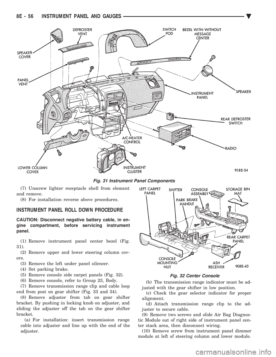
(1) Remove instrument panel center bezel (Fig.
31). (2) Remove upper and lower steering column cov-
ers. (3) Remove the left under panel silencer.
(4) Set parking brake.
(5) Remove console side carpet panels (Fig. 32).
(6) Remove console, refer to Group 23, Body.
(7) Remove transmission range clip and cable loop
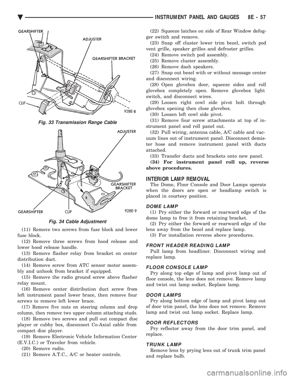
end from post on gear shifter (Fig. 33 and 34). (8) Remove adjuster from tab on gear shifter
bracket. By pushing in locking knob on adjuster, and
sliding the adjuster off the tab on the gear shifter
bracket. (a) For installation: insert transmission range
cable into adjuster and line up with the end of the
adjuster. (b) The transmission range indicator must be ad-
justed with the gear shifter in low position. (c) Check the gear selector indicator for proper
alignment. (d) Attach transmission range clip to the ad-
juster to secure cable.
(9) Remove two screws and slide Air Bag Diagnos-
tic Module out of right side of instrument panel cen-
ter stack area, then disconnect wiring. (10) Remove screw from instrument panel dimmer
module at left of steering column and lower module.
Fig. 31 Instrument Panel Components
Fig. 32 Center Console
8E - 56 INSTRUMENT PANEL AND GAUGES Ä
Page 549 of 2438
(11) Remove two screws from fuse block and lower
fuse block. (12) Remove three screws from hood release and
lower hood release handle. (13) Remove flasher relay from bracket on center
distribution duct. (14) Remove screw from ATC sensor motor assem-
bly and unhook from bracket if equipped. (15) Remove the radio ground screw above flasher
relay mount. (16) Remove center distribution duct screw from
left instrument panel lower brace, then remove four
screws to remove left lower brace.
(17) Remove five nuts on steering column and drop
column, then remove two upper column attaching studs.
(18) Remove two screws and pull out compact disc
player or cubby box, disconnect Co-Axial cable from
compact disc player. (19) Remove Electronic Vehicle Information Center
(E.V.I.C.) or Traveler from vehicle. (20) Remove radio.
(21) Remove A.T.C., A/C or heater controls. (22) Squeeze latches on side of Rear Window defog-
ger switch and remove. (23) Snap off cluster lower trim bezel, switch pod
vent grille, speaker grilles and defroster grilles. (24) Remove switch pod assembly.
(25) Remove cluster assembly.
(26) Remove dash speakers.
(27) Snap out bezel with or without message center
and disconnect wiring. (28) Open glovebox door, squeeze sides and roll
glovebox completely open. Remove glovebox light
switch, and disconnect wires. (29) Loosen right cowl side pivot bolt through
glovebox opening then close glovebox. (30) Loosen left cowl side pivot.
(31) Remove four screw attachments at top of in-
strument panel and roll panel out. (32) Pull wiring, antenna cable, A/C cable and vac-
uum lines out of instrument panel. Disconnect demis-
ter hose and remove instrument panel with ducts
attached. (33) Transfer ducts and brackets onto new panel.
(34) For instrument panel roll up, reverse
above procedures.
INTERIOR LAMP REMOVAL
The Dome, Floor Console and Door Lamps operate
when the doors are open or headlamp switch is
placed in courtesy position.
DOME LAMP
(1) Pry either the forward or rearward edge of the
dome lamp to free it from retaining bracket. (2) Pry either the forward or rearward edge of the
lens away from the bezel and replace lamp. (3) For installation reverse above procedures.
FRONT HEADER READING LAMP
Pull lamp from headliner. Disconnect wiring and
replace lamp.
FLOOR CONSOLE LAMP
Pry along top edge of lamp and pivot lamp out of
floor console, the lens does not remove. Remove lamp
and twist out lamp socket. Replace lamp.
DOOR LAMPS
Pry along bottom edge of lamp and pivot lamp out
of door trim panel, the lens does not remove. Remove
lamp and twist out lamp socket. Replace lamp.
DOOR REFLECTORS
Pry reflector away from the door trim panel, and
replace.
TRUNK LAMP
Remove lens by prying lens out of trunk trim panel
and replace bulb.
Fig. 33 Transmission Range Cable
Fig. 34 Cable Adjustment
Ä INSTRUMENT PANEL AND GAUGES 8E - 57
Page 562 of 2438

CIGAR LIGHTER REPLACEMENT
(1) Remove center bezel assembly (Fig. 23).
(2) Remove center module lower cover or open for-
ward console lid. (3) Unscrew lighter receptacle shell from recepta-
cle and remove from base instrument panel. (4) Disconnect wiring connectors from lighter re-
ceptacle and remove from vehicle. (5) For installation reverse above procedures.
REAR WINDOW DEFOGGER AND/OR FOG LAMP SWITCH REPLACEMENT
(1) Remove center module bezel assembly (Fig. 20).
(2) Remove two switch bezel screws (Fig. 24).
(3) Pull switches and bezel rearward and discon-
nect wiring connector. (4) Remove two switch retaining screws.
(5) Remove switch from bezel.
(6) For installation reverse above procedures.
INTERMITTENT WIPE MODULE REPLACEMENT
(1) Remove lower steering column cover.
(2) Slide intermittent wipe module off of bracket
located on steering column reinforcement (Fig. 25). (3) Disconnect wiring connector from module and
remove module from vehicle. (4) For installation reverse above procedures.
GLOVE BOX LAMP AND SWITCHREPLACEMENT
(1) Disconnect battery and/or pull fuse # 13 before
starting removal procedure. (2) Open glove box door (Fig. 26).
(3) Carefully pry lamp from its mounting surface
with tip of a small screwdriver. (4) Pull lamp from box and disconnect electrical
leads. (5) Remove lamp.
(6) For installation reverse above procedures.
CONSOLETTE ASSEMBLY REPLACEMENT
(1) Remove shifter handle.
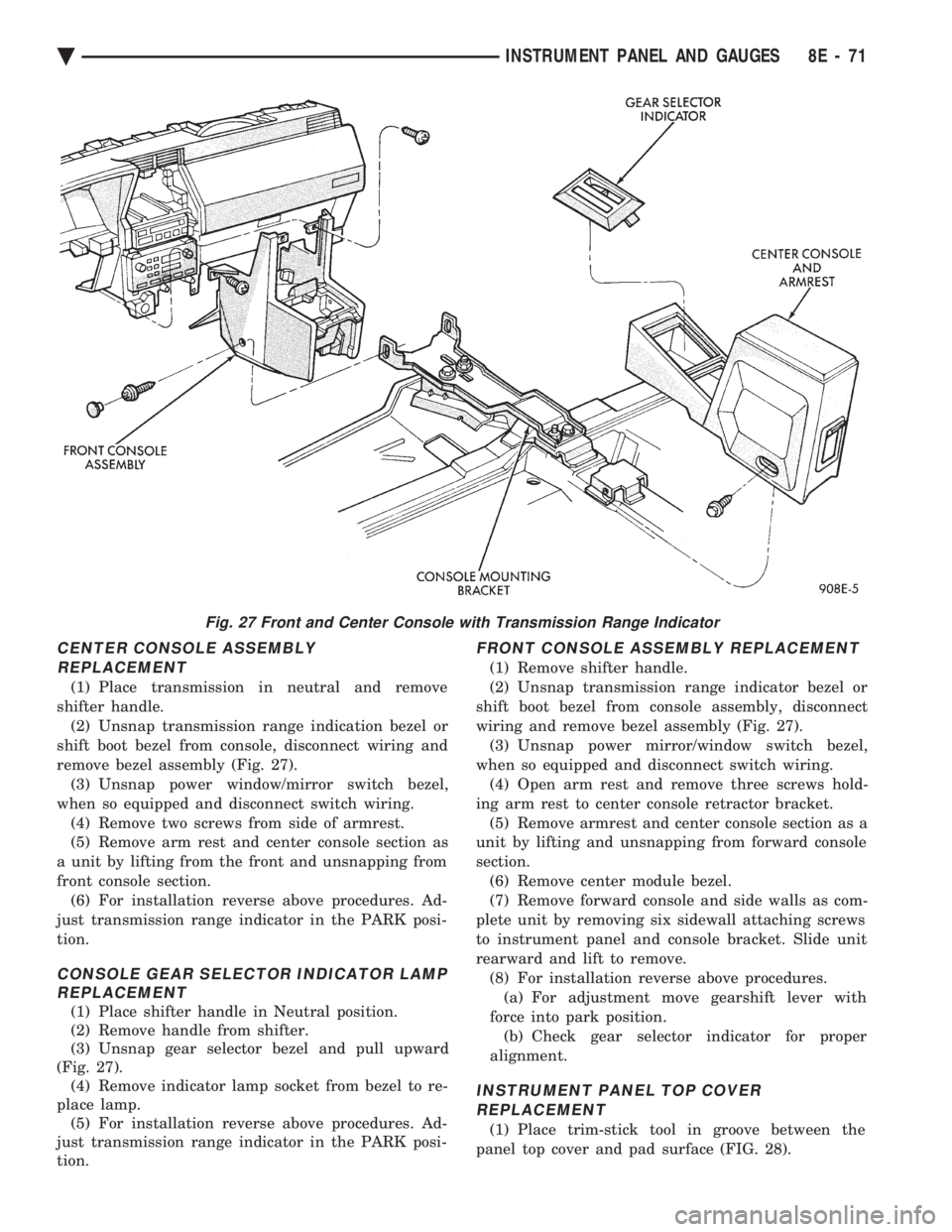
(2) Unsnap transmission range indicator bezel or
shift boot bezel from consolette, disconnect wiring
and remove bezel assembly (Fig. 27). (3) Remove two screws from side of armrest.
(4) Remove four caps which cover attaching
screws. (5) Remove four attaching screws.
(6) Lift consolette up and over shift mechanism to
remove. (7) For installation reverse above procedures.
Fig. 24 Rear Window Defogger and Fog Lamp Switch
Fig. 25 Intermittent Wipe Module
Fig. 26 Glove Box Lamp and Switch
8E - 70 INSTRUMENT PANEL AND GAUGES Ä
Page 563 of 2438
CENTER CONSOLE ASSEMBLY REPLACEMENT
(1) Place transmission in neutral and remove
shifter handle. (2) Unsnap transmission range indication bezel or
shift boot bezel from console, disconnect wiring and
remove bezel assembly (Fig. 27). (3) Unsnap power window/mirror switch bezel,
when so equipped and disconnect switch wiring. (4) Remove two screws from side of armrest.
(5) Remove arm rest and center console section as
a unit by lifting from the front and unsnapping from
front console section. (6) For installation reverse above procedures. Ad-
just transmission range indicator in the PARK posi-
tion.
CONSOLE GEAR SELECTOR INDICATOR LAMP REPLACEMENT
(1) Place shifter handle in Neutral position.
(2) Remove handle from shifter.
(3) Unsnap gear selector bezel and pull upward
(Fig. 27). (4) Remove indicator lamp socket from bezel to re-
place lamp. (5) For installation reverse above procedures. Ad-
just transmission range indicator in the PARK posi-
tion.
FRONT CONSOLE ASSEMBLY REPLACEMENT
(1) Remove shifter handle.
(2) Unsnap transmission range indicator bezel or
shift boot bezel from console assembly, disconnect
wiring and remove bezel assembly (Fig. 27). (3) Unsnap power mirror/window switch bezel,
when so equipped and disconnect switch wiring. (4) Open arm rest and remove three screws hold-
ing arm rest to center console retractor bracket. (5) Remove armrest and center console section as a
unit by lifting and unsnapping from forward console
section. (6) Remove center module bezel.
(7) Remove forward console and side walls as com-
plete unit by removing six sidewall attaching screws
to instrument panel and console bracket. Slide unit
rearward and lift to remove. (8) For installation reverse above procedures.(a) For adjustment move gearshift lever with
force into park position. (b) Check gear selector indicator for proper
alignment.
INSTRUMENT PANEL TOP COVER REPLACEMENT
(1) Place trim-stick tool in groove between the
panel top cover and pad surface (FIG. 28).
Fig. 27 Front and Center Console with Transmission Range Indicator
Ä INSTRUMENT PANEL AND GAUGES 8E - 71
Page 584 of 2438
RADIO REMOVALÐAA BODY
(1) Remove center bezel by pulling straight back
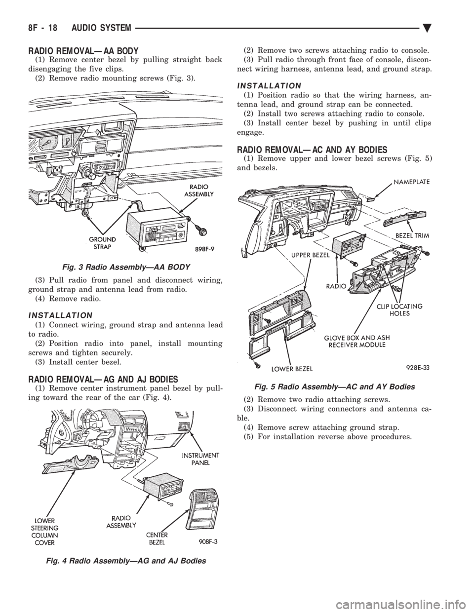
disengaging the five clips. (2) Remove radio mounting screws (Fig. 3).
(3) Pull radio from panel and disconnect wiring,
ground strap and antenna lead from radio. (4) Remove radio.
INSTALLATION
(1) Connect wiring, ground strap and antenna lead
to radio. (2) Position radio into panel, install mounting
screws and tighten securely. (3) Install center bezel.
RADIO REMOVALÐAG AND AJ BODIES
(1) Remove center instrument panel bezel by pull-
ing toward the rear of the car (Fig. 4). (2) Remove two screws attaching radio to console.
(3) Pull radio through front face of console, discon-
nect wiring harness, antenna lead, and ground strap.
INSTALLATION
(1) Position radio so that the wiring harness, an-
tenna lead, and ground strap can be connected. (2) Install two screws attaching radio to console.
(3) Install center bezel by pushing in until clips
engage.
RADIO REMOVALÐAC AND AY BODIES
(1) Remove upper and lower bezel screws (Fig. 5)
and bezels.
(2) Remove two radio attaching screws.
(3) Disconnect wiring connectors and antenna ca-
ble. (4) Remove screw attaching ground strap.
(5) For installation reverse above procedures.
Fig. 3 Radio AssemblyÐAA BODY
Fig. 4 Radio AssemblyÐAG and AJ Bodies
Fig. 5 Radio AssemblyÐAC and AY Bodies
8F - 18 AUDIO SYSTEM Ä
Page 585 of 2438
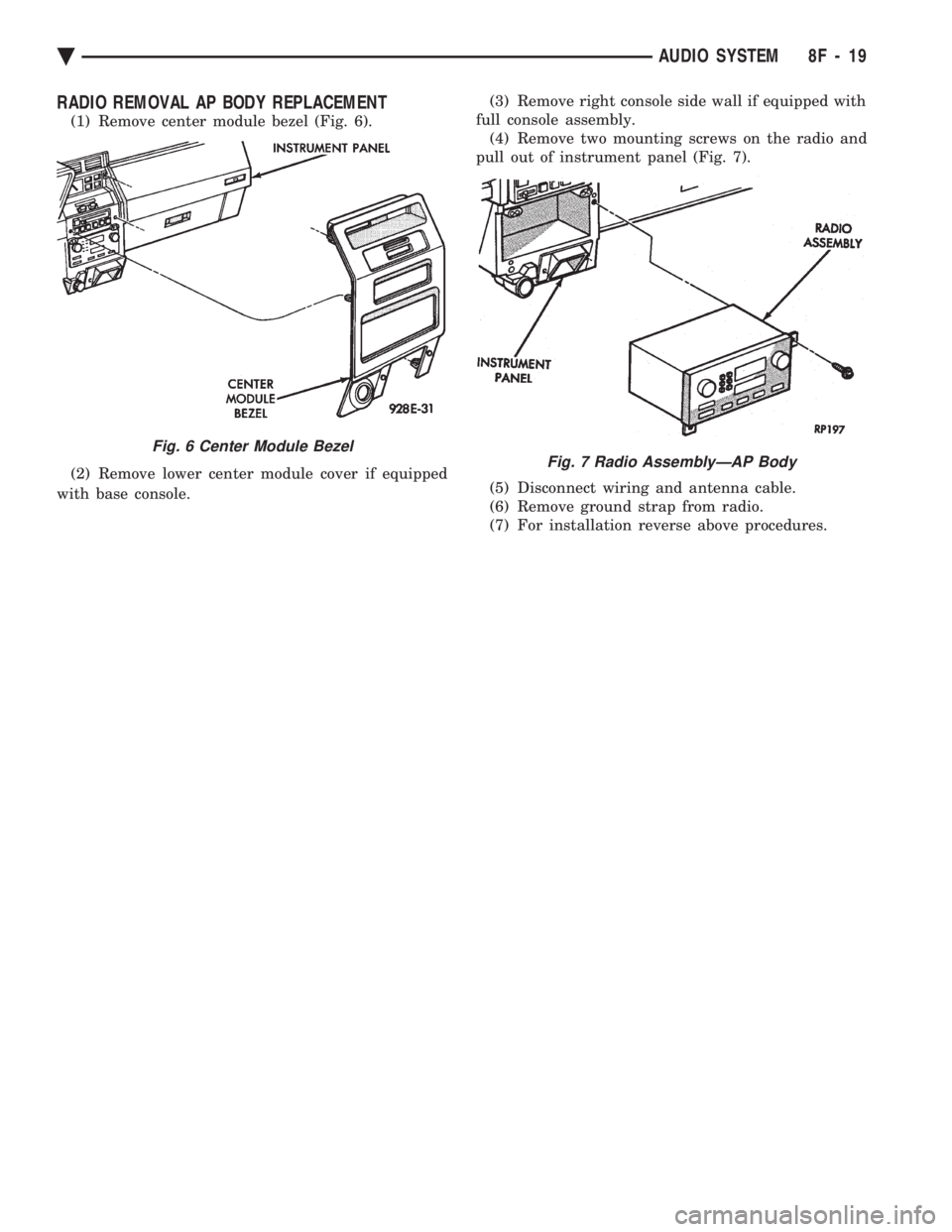
RADIO REMOVAL AP BODY REPLACEMENT
(1) Remove center module bezel (Fig. 6).
(2) Remove lower center module cover if equipped
with base console. (3) Remove right console side wall if equipped with
full console assembly. (4) Remove two mounting screws on the radio and
pull out of instrument panel (Fig. 7).
(5) Disconnect wiring and antenna cable.
(6) Remove ground strap from radio.
(7) For installation reverse above procedures.
Fig. 6 Center Module Bezel
Fig. 7 Radio AssemblyÐAP Body
Ä AUDIO SYSTEM 8F - 19
Page 596 of 2438

COMPACT DISC PLAYER
WARNING: USE OF THE CONTROLS, ADJUST-
MENTS, OR SERVICE PROCEDURES NOT SPECI-
FIED HERE OR IN THE OWNER MANUAL MAY
RESULT IN HAZARDOUS RADIATION EXPOSURE.
REPAIR PROCEDURES SHOULD ONLY BE PER-
FORMED BY A TRAINED TECHNICIAN.
DIAGNOSIS TEST
Power to the compact disc player is supplied by the
radio through the CD interface cable. The compact
disc player will only work with the radio system
turned ON. When a compact disc is inserted with the
label side facing up, the disc is automatically loaded
and will begin to play. The CD player may eject the disc with a display of
E under the following conditions:
² The surface of the disc is dirty or wet
² The disc was inserted with the label side facing
down
² The disc is defective
² The CD player may skip or mute while playing a
disc under severe vibration conditions example pot
holes, railroad tracks, etc.
² If the CD player becomes too hot at temperatures
above 60ÉC (140 ÉF) the CD player will shut down
with a display of HOT until it cools down. Refer to
the Audio Diagnostic Charts.
COMPACT DISC PLAYER REPLACEMENT
With intergral compact disc player refer to Radio
Removal.
AJ BODY
(1) Remove center instrument panel bezel by pull-
ing toward the rear of the car. (2) Remove two screws attaching disc player to
console (Fig. 36). (3) Pull disc player out of console and disconnect
interface cable. (4) To install compact disc player, above the re-
moval procedures.
Fig. 36 Compact Disc Player
8F - 30 AUDIO SYSTEM Ä
Page 681 of 2438
AA .............................................................................74
Low Fuel
AA ...........................................................................103
AP ............................................................................161
AC, AY...............................................................PC194
AG, AJ ............................................................5269245
Low Washer Fluid
AA, AC, AY .............................................................74
AP ............................................................................161
AG, AJ ............................................................4437661
Oil Pressure
All .......................................................................PC194
Trunk Open
AA, AC, AY .............................................................74
AP ............................................................................161
AG, AJ ............................................................4437661
Theft Alarm Set
AC, AY....................................................................168
AG, AJ ............................................................4437661
Turn Signal (MIC)
AA ...........................................................................103
AC, AG, AJ, AP, AY .......................................PC194
Turn Signal (EIC)
AA, AY ..............................................................PC194
Seat Belt (MIC)
AA ...........................................................................103
AC, AG, AJ, AP, AY .......................................PC194
Seat Belt (EIC)
AA, AY ..............................................................PC194
AJ ............................................................................103
DIMMER CONTROLLED LAMPS
Service procedures for most of the lamps in the in-
strument panel, Instrument cluster and switches are
located in Group 8E, Instrument Panel and Gauges. A/C Heater Control
All ..............................................................................37
Automatic Temperature Control
All ....................................................................4437661
Column Gearshift Indicator
AA, AC, AY ...........................................................161
Console Gearshift Indicator
AP ............................................................................194
AA, AG, AJ ............................................................161
Fog Lamp Switch Symbol
AG ......................................................................PC194
Headlamp Dimmer Switch
AG, AJ ......................................................................37
Headlamp Switch Symbol
AC, AY....................................................................161
AG, AJ ......................................................................37
Heater Control
All ............................................................................158
EVIC
AJ...........................................................................ASC
Instrument Cluster (MIC)
All .......................................................................PC194
Instrument Cluster (EIC) AA, AY .....................................................................74
Message Center
AA, AC, AY .............................................................74
AP ............................................................................161
Navigator/Travel Companion
AA, AJ ......................................................................74
Radio
All ..........................................................................ASC
Rear Defogger Switch
Not Serviceable, Replace Switch
Rear Wiper Switch
AG .............................................................................37
Theft Alarm
AC, AY....................................................................161
Top Lift Switch
AJ ....................................................................5268053
Travel Computer
All ..........................................................................ASC
Turbo Gauge
AP ............................................................................161
Windshield Wiper Switch
AG, AJ ......................................................................37
NON-DIMMING LAMPS
Service procedures for most of the lamps in the fol-
lowing list can be found in Group 23, Body. Some
components have lamps that can only be serviced by
a Authorized Service Center (ASC) after the compo-
nent is removed from the vehicle. Contact local
dealer for location of nearest ASC. Ash Receiver
AA .............................................................................74
AC, AP, AY ............................................................161
AG, AJ ......................................................................37
Center Console Rear
AJ ............................................................................906
Cigar Lighter
AA, AP ....................................................................161
Courtesy
AA, AC, AY-S .....................................................214-2
AJ ............................................................................906
AY-P.....................................................................212-2
Dome
ALL ......................................................................211-2
Engine Compartment
All ............................................................................105
Glove Compartment
All ..........................................................................1891
Ignition Lock
All ..............................................................................37
Inside Rear View Mirror
AJ ............................................................................168
Overhead Console
AA ...........................................................................912
AC, AY....................................................................906
AG, AJ, AP .........................................................212-2
Reading Lamp Front
All ............................................................................906
Ä LAMPS 8L - 39