1993 CHEVROLET PLYMOUTH ACCLAIM center console
[x] Cancel search: center consolePage 684 of 2438
FRONT IMPACT SENSORS
The driver air bag system is a safety device de-
signed to reduce the risk of fatality or serious injury,
caused by a frontal impact of the vehicle. The impact sensors provide verification of the di-
rection and severity of the impact. Three impact sen-
sors are used. One is called a safing sensor. It is
located inside the diagnostic module which is
mounted on the floor pan, just forward of the center
console. The other two sensors are mounted on the
upper crossmember of the radiator closure panel on
the left and right side of the vehicle under the hood. The impact sensors are threshold sensitive switches
that complete an electrical circuit when an impact
provides a sufficient G force to close the switch. The
sensors are calibrated for the specific vehicle and re-
act to the severity and direction of the impact.
CLOCKSPRING
The clockspring is mounted on the steering column
behind the steering wheel, and is used to maintain a
continuous electrical circuit between the wiring har-
ness and the driver's air bag module. This assembly
consists of a flat ribbon-like electrically conductive
tape which winds and unwinds with the steering
wheel rotation.
DIAGNOSTIC MODULE
The Air Bag System Diagnostic Module (ASDM)
contains the safing sensor and energy reserve capac-
itor. The ASDM monitors the system to determine
the system readiness. The ASDM will store sufficient
energy to deploy the air bag for only two minutes af-
ter the battery is disconnected. If both front impact
sensors are open the air bag could be deployed up to
9.5 minutes after the battery is disconnected. The
ASDM contains on-board diagnostics, and will illumi-
nate the AIR BAG warning lamp in the cluster when
a fault occurs.
STORAGE
The air bag module must be stored in its original
special container until used for service. Additionally,
it must be stored in a clean, dry environment, away
from sources of extreme heat, sparks, and sources of
high electrical energy. Always place or store the
module on a surface with the trim cover facing up to
minimize movement in case of accidental deploy-
ment.
HANDLING LIVE MODULE
At no time should any source of electricity be per-
mitted near the inflator on the back of the module.
When carrying a live module, the trim cover should
be pointed away from the body to minimize injury in
the event of accidental deployment. In addition, if
the module is placed on a bench or other surface, the plastic trim cover should be face up to minimize
movement in case of accidental deployment. When handling a steering column with an air bag
module attached, never place the column on the floor
or other surface with the steering wheel or module
face down.
DEPLOYED MODULE
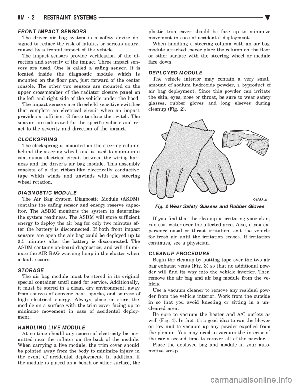
The vehicle interior may contain a very small
amount of sodium hydroxide powder, a byproduct of
air bag deployment. Since this powder can irritate
the skin, eyes, nose or throat, be sure to wear safety
glasses, rubber gloves and long sleeves during
cleanup (Fig. 2).
If you find that the cleanup is irritating your skin,
run cool water over the affected area. Also, if you ex-
perience nasal or throat irritation, exit the vehicle
for fresh air until the irritation ceases. If irritation
continues, see a physician.
CLEANUP PROCEDURE
Begin the cleanup by putting tape over the two air
bag exhaust vents (Fig. 3) so that no additional pow-
der will find its way into the vehicle interior. Then
remove the air bag and air bag module from the ve-
hicle. Use a vacuum cleaner to remove any residual pow-
der from the vehicle interior. Work from the outside
in so that you avoid kneeling or sitting in a un-
cleaned area. Be sure to vacuum the heater and A/C outlets as
well (Fig. 4). In fact it's a good idea to run the blower
on low and to vacuum up any powder expelled from
the plenum. You may need to vacuum the interior of
the car a second time to recover all of the powder. Place the deployed bag and module in your auto-
motive scrap.
Fig. 2 Wear Safety Glasses and Rubber Gloves
8M - 2 RESTRAINT SYSTEMS Ä
Page 737 of 2438
POWER MIRRORS
CONTENTS
page page
AUTOMATIC DAY/NIGHT INSIDE MIRROR .... 7
AUTOMATIC DAY/NIGHT INSIDE MIRROR WITH ULTRALIGHT HEADLAMP CONTROL ....... 7
GENERAL INFORMATION .................. 1
HEATED MIRROR ........................ 2
INSIDE MIRROR/READING LAMPS BULB/LENS REPLACEMENT ........................ 6
INSIDE MIRROR/READING LAMPS REPLACEMENT ........................ 6
MIRROR ASSEMBLY REPLACEMENTÐAA BODY.5
MIRROR ASSEMBLY REPLACEMENTÐ AC AND AY BODIES .................... 5
MIRROR ASSEMBLY REPLACEMENTÐAG BODY.5
MIRROR ASSEMBLY REPLACEMENTÐAJ BODY.5
MIRROR ASSEMBLY REPLACEMENTÐAP BODY.5
MIRROR MOTOR TEST PROCEDURE ........ 2
MIRROR SWITCH REPLACEMENTÐAA BODY . 3
MIRROR SWITCH REPLACEMENTÐAC AND AY BODIES .............................. 4
MIRROR SWITCH REPLACEMENTÐAG AND AJ BODIES .............................. 3
MIRROR SWITCH REPLACEMENTÐAP BODY . 4
MIRROR SWITCH TEST PROCEDURE ....... 2
TEST PROCEDURES ...................... 2
GENERAL INFORMATION
Electrically operated power mirrors are available
on all car lines. The mirrors are controlled by a sin-
gle switch assembly located either on the driver's
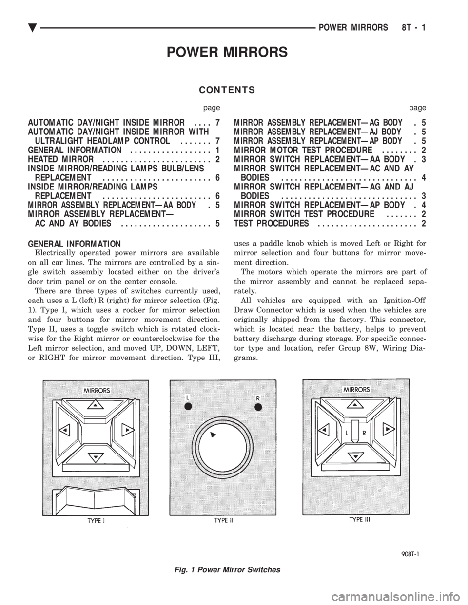
door trim panel or on the center console. There are three types of switches currently used,
each use s a L (left) R (right) for mirror selection (Fig.
1). Type I, which uses a rocker for mirror selection
and four buttons for mirror movement direction.
Type II, uses a toggle switch which is rotated clock-
wise for the Right mirror or counterclockwise for the
Left mirror selection, and moved UP, DOWN, LEFT,
or RIGHT for mirror movement direction. Type III, uses a paddle knob which is moved Left or Right for
mirror selection and four buttons for mirror move-
ment direction.
The motors which operate the mirrors are part of
the mirror assembly and cannot be replaced sepa-
rately. All vehicles are equipped with an Ignition-Off
Draw Connector which is used when the vehicles are
originally shipped from the factory. This connector,
which is located near the battery, helps to prevent
battery discharge during storage. For specific connec-
tor type and location, refer Group 8W, Wiring Dia-
grams.
Fig. 1 Power Mirror Switches
Ä POWER MIRRORS 8T - 1
Page 933 of 2438
Wiring Diagram
Name Sheet Number
Illumination Lamp ...........................68
Resistor .................................68
Horn System ...............................65
Horn (Hi-Note) .............................65
Horn (Lo-Note) ............................65
Horn Relay ...............................65
Horn Switch ..............................65
Hydraulic Modulator (ABS) 41
Ignition Coil .......................... .14, 20, 29
Ignition Off-Draw Connector .....................5,7
Ignition Switch .............................4,11
Brake Warning Lamp Switch ....................11
Park Brake Switch ...........................11
Illuminated Entry .............................58
Illuminated Entry Module ......................58
Left Door Illuminated Entry Switch ................58
Right Door Illuminated Entry Switch ...............58
Illuminated Visor Vanity Mirror ....................73
Injector(s) ........................... .16, 17, 26
Instrument Panel Wiring to Left Body ...............123
Instrument Panel Wiring to Right Body ..............124
Instrument Panel to Multi-Function Switch ............116
Interface Grommet ............................47
Intermittent Wiper System .................... .63, 64
Intermittent Windshield Wiper Motor ...............64
Intermittent Wiper Control Module ................64
Multi-function Switch .........................63
Windshield Washer Low Fluid Level Sensor ...........63
Windshield Washer Pump Motor .................63
Key-In Switch ...............................46
Key-In Warning Chimes .........................45
Lamp Outage Module ........................ .115
Lamps A/C Lamps ...............................52
Ash Receiver Lamp ..........................52
Back-Up Lamps ............ .93, 94, 98, 102, 103, 105
Cargo Lamp ........................ .76, 96, 100
Center High Mounted Stop Lamp ........94, 98, 102, 105
Cigar Lighter Lamp ..........................52
Cluster Lamp ..............................77
Courtesy Lamps ............................76
Dome Lamp ..............................73
Fog Lamp-Left .............................56
Fog Lamp-Right ............................55
Front Reading Lamp .........................75
Glove Box Lamp ............................54
Halo Lamp ...............................54
Headlamp-Left .............................56
Headlamp Out Lamp .........................77
Headlamp-Right ............................55
Heater Lamp ..............................52
Illumination Lamp ..................... .68, 71, 72
Left Front Door Ajar Lamp .....................77
Left Rear Door Ajar Lamp ......................77
Left Side Marker Lamp ........................93
Left Tail/Stop and Turn Lamp ....................93
License Lamp ................... .93, 98, 102, 104Wiring Diagram
Name Sheet Number
Liftgate Ajar Lamp ..........................77
Low Washer Fluid Lamp .......................77
Park/Turn Lamp-Left .........................56
Park/Turn Lamp-Right ........................55
Radio Lamp ...............................52
Reading Lamps ............................75
Right Front Door Ajar Lamp ....................77
Right Rear Door Ajar Lamp .....................77
Seat Belt Warning Lamp .......................45
Side Marker Lamp-Left Front ....................56
Side Marker Lamp-Left Rear ...........93, 98, 102, 103
Side Marker Lamp-Right Front ...................55
Side Marker Lamp-Right Rear ..........94, 98, 102, 105
Stop Lamp Out Lamp ........................77
Tail Lamp Out Lamp .........................77
Tail/Stop Lamp-Left Rear ................... .93, 98
Tail/Stop Lamp-Right Rear .................. .94, 98
Tail/Stop and Turn Lamp-Left Rear .......93, 98, 102, 103
Tail/Stop and Turn Lamp-Right Rear ......94, 98, 102, 105
Transmission Range Indicator Lamp ...............76
Underhood Lamp ........................ .39, 40
Visor Vanity Mirror Lamp ......................73
Left Power Seat System ........................66
Center Switch .............................66
Front Switch ..............................66
Power Seat Motors ..........................66
Rear Switch ...............................66
License Lamp ..................... .93, 98, 102, 104
Lighter-Cigar ................................52
MAP Sensor .......................... .13, 19, 30
Message Center ..............................60
Traveler and Message Center ....................60
Mini Trip Computer ...........................60
Modules Airbag System Diagnostic Module .................47
Daytime Running Light Module ..................57
Illuminated Entry Module ......................58
Intermittent Wiper Control Module ................64
Lamp Outage Module ..................... .95, 99
Motors A/C-Heater Blower Motor ................... .71, 72
Fuel Pump Motor ...........................69
Heater Blower Motor .........................68
Idle Air Control Motor .................. .12, 18, 30
Intermittent Wiper Motor ......................64
Power Door Locks Motors .................. .85, 86
Power Seat Motors ..........................66
Power Window Motors .................... .81, 82
Radiator Fan Motor ...................... .32, 33
Starter Motor ............................9,10
Windshield Washer Pump Motor .................63
Name Brand Speaker Relay ......................89
Optical Horn Headlamp Dimmer Switch .............1,50
Overhead Console, Dome, Reading and Visor Vanity Lamps ..................... .73, 74, 75, 76
Ambient Temperature Sensor ....................75
Cargo Lamp ..............................76
Ä WIRING DIAGRAMS AA-BODY 8W - 183
Page 934 of 2438
Wiring Diagram
Name Sheet Number
Dome Lamp ..............................73
Front Reading Lamps .........................75
Illuminated Visor Vanity Lamps ..................73
Left Front Door Courtesy Lamp ..................76
Left Front Door Jamb Switch ....................75
Left Rear Door Courtesy Lamp ...................76
Left Rear Door Jamb Switch ....................76
Left Lamp Switch ...........................75
Overhead Console ...........................73
Right Front Door Courtesy Lamp .................76
Right Front Door Jamb Switch ...................74
Right Rear Door Courtesy Lamp ..................76
Right Rear Door Jamb Switch ...................73
Transmission Range Indicator Lamp ...............76
Power Assist System ..........................67
Power Door Interlock System ....................106
Power Door Lock Inhibit Relay ...................106
Power Door Lock System .................... .85, 86
Connectors and Door Lock Switch Function ........85, 86
Left Front Door Lock Motor .....................85
Left Front Door Lock Switch ....................85
Left Rear Door Lock Motor .....................85
Right Front Door Lock Motor ....................86
Right Front Door Lock Switch ...................86
Right Rear Door Lock Motor ....................86
Power Remote Heated Mirrors ..................79, 80
Heated Mirror .......................... .79, 80
Left Power Mirror ...........................79
Right Power Mirror ..........................80
Switch ..................................79
Switch Function ............................79
Powertrain Control Module (PCM) .....12, 13, 14, 15, 16, 17,
18, 19, 20, 21, 22, 23, 24, 25, 27, 28, 29, 30, 31, 59
Powertrain Control Module Flex Fuel Connector (2.5L Engine) ............................ .125
Powertrain Control Module Connector (2.5L) ...........108
Powertrain Control Module Connector (3.0L) .......109, 110
Power Window Connector and Switch Functions .........83
Power Window System ..................... .81, 82
Left Front Door Window Lift Master Switch ...........81
Left Front Window Regulator Motor ...............81
Left Rear Window Regulator Motor ................81
Left Rear Door Window Lift Switch ................81
Right Front Window Regulator Motor ...............82
Right Front Door Window Lift Switch ...............82
Right Rear Window Regulator Motor ...............82
Right Rear Door Window Lift Switch ...............82
Radiator Fan Motor ........................ .32, 33
Rear End Lighting (Chrysler/Dodge) with Lamp Outage ....................... .99, 100, 101, 102
Cargo Lamp ............................. .100
Center High Mounted Stop Lamp ................102
Lamp Outage Module .........................99
Left Back-Up Lamp ........................ .102
Left Side Marker Lamp ...................... .102
Left Tail/Stop and Turn Lamp ...................102
License Lamp ............................ .102Wiring Diagram
Name Sheet Number
Right Back-Up Lamp ....................... .102
Right Side Marker Lamp ..................... .102
Right Tail/Stop and Turn Lamp ..................102
Rear End Lighting (Chrysler/Dodge) without Lamp Outage ..................... .103, 104, 105
Center High Mounted Stop Lamp ................105
Left Back-Up Lamp ........................ .103
Left Side Marker Lamp ...................... .103
Left Tail/Stop and Turn Lamp ...................103
License Lamp ............................ .104
Right Back-Up Lamp ....................... .105
Right Side Marker Lamp ..................... .105
Right Tail/Stop and Turn Lamp ..................105
Rear End Lighting (Plymouth) with Lamp Outage ......................... .95, 96, 97, 98
Cargo Lamp ..............................96
Center High Mounted Stop Lamp .................98
Lamp Outage Module .........................95
Left Back-Up Lamp ..........................98
Left Side Marker Lamp ........................98
Left Tail/Stop and Turn Lamp ....................98
License Lamp .............................98
Right Back-Up Lamp .........................98
Right Side Marker Lamp .......................98
Right Tail/Stop and Turn Lamp ...................98
Rear End Lighting (Plymouth) without Lamp Outage ............................ .92, 93, 94
Center High Mounted Stop Lamp .................94
Left Back-Up Lamp ..........................93
Left Side Marker Lamp ........................93
Left Tail/Stop and Turn Lamp ....................93
License Lamp .............................93
Right Back-Up Lamp .........................94
Right Side Marker Lamp .......................94
Right Tail/Stop and Turn Lamp ...................94
Relay Bank ............................... .107
Relays ABS Pump Motor Relay .......................41
ABS System Relay ..........................43
ABS Warning Lamp Relay ......................43
A/C Compressor Clutch Relay .................32, 33
Automatic Shut-down Relay ...............14, 20, 28
Back-Up Lamp Relay .........................37
Engine Starter Relay ........................9,10
Fan Control Relay ....................... .32, 33
Fog Lamp Relay ............................48
Fuel Pump Relay ...........................70
Horn Relay ...............................65
Power Door Lock Inhibit Relay ..................106
Safety Shut-down Relay .......................35
Speaker Relay (NBS) .........................89
Time Delay Relay ...........................54
Seat Belt Warning System .................... .45, 46
Cigar Lighter ..............................45
Headlamp Switch Connector ....................46
Key-in Switch .............................46
Left Front Door Jamb Switch ....................46
8W - 184 WIRING DIAGRAMS AA-BODY Ä
Page 1283 of 2438
WIRING DIAGRAMS AG-AJ BODY
ALPHABETICAL INDEX
Wiring Diagram
Name Sheet Number
A/C Compressor Clutch .........................89
A/C and Heater System ..................... .91, 92
A/C Compressor Clutch Relay ...................91
A/C Low Pressure Switch ......................91
A/C High Pressure Switch ......................92
A/C Cycling Switch ..........................92
ABS Warning Lamp Diode .......................69
Airbag System ........................... .84, 85
Clock Spring ..............................84
Diagnostic Module ..........................84
Interface Grommet ..........................85
Left Airbag Sensor ..........................85
Right Airbag Sensor .........................85
Squib (Airbag Igniter) ........................84
Air Conditioning System ........................90
A/C Blower Motor ...........................90
A/C/Heater Blower Motor Resistor .................90
A/C Switch ...............................90
Blower Switch .............................90
Defrost Switch .............................90
Illumination Lamps Switch .....................90
Alarm, Security Module ....................... .127
Ambient Air Temperature Sensor ...............117, 119
Anti-Lock Brake System (Except Turbo 3) .............170
Anti-Lock Brake System Controller ..........68, 69, 70, 71
Anti-Lock Brake System .................68, 69, 70, 71
ABS Controller .................... .68, 69, 70, 71
ABS Hydraulic Modulator ......................68
ABS Pump Motor Relay .......................68
ABS System Relay ..........................69
ABS Warning Lamp Diode ......................69
ABS Warning Switch Lamp Switch ................70
Brake Switch ..............................70
Left Front Wheel Sensor .......................71
Left Rear Wheel Sensor .......................71
Park Brake Switch ...........................70
Right Front Wheel Sensor ......................71
Right Rear Wheel Sensor ......................71
Automatic Shutdown Relay ..................20, 27, 33
Battery ...........................1,9,11,53,56
Body Computer ......................... .165, 166
Body Computer #1 ............................40
Body Computer (Mechanical Cluster) ..............79, 80
Body Computer #2 ............................40
Body Computer (Electronic Cluster) ...............81, 82
Body Wiring to Left Instrument Panel ...............147
Body Wiring to Right Instrument Panel ...........150, 151
Bulkhead Disconnect (50-Way) ................153, 154
Center High Mounted Stop Lamp (AG) ...............140
Center High Mounted Stop Lamp (J-21) ..............141
Center High Mounted Stop Lamp (J-27) ..............142
Charging System (2.5L and Turbo) ................9,10Wiring Diagram
Name Sheet Number
Battery ...................................9
Data Link Connector ..........................9
Generator ................................10
Power Distribution Center ....................9,10
Powertrain Control Module ......................9
Charging System (3.0L) ..................... .11, 12
Battery ..................................11
Generator ................................12
Power Distribution Center .................. .11, 12
Cigar Lighter ................................51
Circuit Breakers (Fuse Cavity #2) ...........8,42,110, 111
Circuit Breakers (Fuse Cavity #3) ..............5,53,116
Clockspring .......................... .59, 65, 84
Clutch Pedal Position Jumper ..................13, 15
Clutch Pedal Position Switch .....................14
Combo Flasher ..............................56
Data Link Connector ..................9,19,25,34,72
Daytime Running Lights Module Connector ............173
Decklid Lock Sense Switch ..................... .102
Dimming Interior Lamps & Headlamp Switch .........51, 52
Ash Receiver Lamp ..........................51
Cluster Lamps .............................52
Cigar Lighter ..............................51
Console Switch Module .......................51
A/C Heater Control Switch Lamp .................52
Headlamp Switch ...........................51
Fog Lamp Switch ...........................51
Fuse Panel Switch ...........................51
Left Pod Lamps ............................51
Left Switch Pod ............................51
Transmission Range Lamp .....................51
Diode ....................................89
Diode Package ....................... .83, 102, 104
Distributor .............................. .21, 26
Dome and Courtesy Lamps (AG) ...............125, 126
Cargo Lamp ............................. .126
Dome Lamp ............................. .126
Front Reading Lamps ....................... .126
Front Reading Lamp Switch ................... .126
Glove Box Lamp & Switch .................... .125
Halo Light .............................. .125
Liftgate Ajar Switch ........................ .125
Vanity Mirror Lamps ....................... .126
Vanity Mirror Lamp Switch ................... .126
Dome, Reading and Courtesy Lamps (J-27 Only) .....121, 122
Courtesy Lamp ........................... .121
Decklid Ajar Switch ........................ .122
Glove Box Lamp .......................... .121
Halo Light .............................. .121
Left Door Courtesy Lamp .................... .122
Rear Mirror Courtesy Lamp ................... .122
Right Door Courtesy Lamp ................... .121
Ä WIRING DIAGRAMS AG-AJ BODY 8W - 533
Page 1286 of 2438
Wiring Diagram
Name Sheet Number
Fuel Gauge ............................. .107
Fuel Pump Module ........................ .107
Fuel Pump Relay .......................... .108
Fuel Tank Gauge Level Sending System ............107
Fuse Application Chart (Engine Compartment) ......1,2,3,4
Fuse Application Chart (Instrument Panel) .........5,6,7,8
Fuse Block ............................... .143
Fuses Fuse 1 ...........................8,42,90,93
Fuse 5 ....................8,13,14,39,42,84,96
Fuse 6 ..............................8,42,56
Fuse 7 .............................8,42,105
Fuse 8 ................................5,52
Fuse 9 ................................5,55
Fuse 10 ..........................5,10,12,54
Fuse 11 ..........................5,60,84,88
Fuse 12 ...............................5,63
Fuse 14 .....................7,42,70,73,77,84
Fuse 15 ..........................7,42,59,70
Fuse 17 .........................6,53, 133, 137
Fuse 18 .........................6,53, 133, 137
Fuse 19 ...............................6,54
Fuse 20 ...............................6,54
Fuse 21 ..........................5,10,12,59
Fuse 22 ...............................5,65
Fuse 25 .......................8,94,95,98,100
Fuse 26 ..............8,16,73,77,94, 121, 123, 125
Fuse 27 ..........................7,42,61,63
Fuse 28 .............................7,42,67
Fuse 36 ...........................1,9,11,56
Fuse 37 ..................................1
Fuse 40 ..............................2,9,11
Fuse 41 ..............................2,9,11
Fuse 42 ...........................2,9,11,18
Fuse 43 ..................................2
Fuse 44 .............................2,10,12
Fuse 45 .............................2,10,12
Fuse 46 ..............................2,9,11
Fuse 47 ..............................2,9,11
Fuse 48 .............................1,10,12
Fuse 50 .............................1,10,12
Fuse 51 .............................2,10,12
Fuse 52 .............................4,10,12
Fuse 53 .............................4,10,12
Fuse 55 ..........................2,10,12,13
Fuse 56 ........................3,10,12,54,84
Fuse 57 ..........................3,10,12,54
Fuse 58 .............................1,10,12
Generator .............................. .10, 12
Glove Box Lamp Switch ................... .101, 103
Headlamp Switch ......................... .51, 55
Headlamp Switch System .................. .53, 54, 55
Battery ..................................53
Fog Lamp Relay ............................55
Fog Lamp Switch ...........................55
Headlamp Switch ...........................55
High Beam Relay ...........................53Wiring Diagram
Name Sheet Number
Left Pod Light .............................55
Low Beam Relay ............................53
Optical Horn Switch .........................55
Park Lamp Relay ...........................53
Parking Switch .............................55
Turn Signal Switch ..........................55
Heated Oxygen Sensor ................... .17, 24, 32
Heated Rear Window ......................8,94,95
Heated Rear Window Switch .................8,94,95
Heater System ...............................93
Blower Motor ..............................93
Blower Motor Resistor ........................93
Blower Switch .............................93
Illumination Lamp Switch ......................93
High Beam Relay ...........................6,53
Horn System ...............................65
Clockspring ...............................65
Horn Relay ...............................65
Horn Switch ..............................65
Left Horn (Lo-Note) ..........................65
Right Horn (Hi-Note) .........................65
Idle Air Control Motor ...................... .17, 23
Ignition Coil ............................. .19, 23
Ignition Switch ...........................2,7,42
Instrument Panel Fuse Application Chart ..........5,6,7,8
Intermittent Wiper System .................... .66, 67
Intermittent Windshield Wiper Motor ...............67
Park Switch ...............................67
Washer Relay .............................66
Windshield Washer Low Fluid Level Sensor ...........67
Windshield Washer Pump Motor .................67
Wiper Switch ..............................66
Interface Grommet ............................85
Key Disarm Switch ....................... .115, 116
Lamp Outage Module Connectors ..................174
Lamps A/C Heater Control Lamp ......................52
Ash Receiver Lamp ..........................51
Back-Up Lamps ...........128, 131, 133, 134, 137, 138
Cargo Lamp ............................. .126
Center High Mounted Stop Lamp ..........140, 141, 142
Cluster Lamps .............................52
Console Switch Module Lamp ...................51
Courtesy Lamps ................ .121, 122, 123, 124
Dome Lamp ......................... .118, 126
Dummy Lamp .......................... .45, 46
Fog Lamp-Left ......................... .43, 47
Fog Lamp-Right ........................ .44, 48
Glove Box Lamp ............. .101, 103, 121, 123, 125
Halo Light ....................... .121, 123, 125
Headlamp, High Beam .......43, 44, 45, 46, 47, 48, 49, 50
Headlamp, Low Beam .......43, 44, 45, 46, 47, 48, 49, 50
Illumination Lamp ....................... .90, 93
Left Pod Lamps ......................... .51, 55
License Lamp .................. .128, 131, 133, 137
Park and Turn Signal Lamp-Left ........43, 45, 47, 49, 50
Park and Turn Signal Lamp-Right .......44, 46, 48, 49, 50
8W - 536 WIRING DIAGRAMS AG-AJ BODY Ä
Page 1287 of 2438
Wiring Diagram
Name Sheet Number
Reading Lamps ....................... .124, 126
Side Marker Lamp-Left .........45, 49, 50, 128, 132, 136
Side Marker Lamp-Right ........46, 49, 50, 131, 135, 139
Stop Lamp .......... .59, 128, 131, 132, 135, 136, 139
Tail Lamps .......128, 131, 132, 134, 135, 136, 138, 139
Trunk Lamp .......................... .122, 124
Transmission Range Lamp .....................51
Turn Lamp .................... .132, 135, 136, 139
Turn Signal Lamp-Left ...................... .128
Turn Signal Lamp-Right ..................... .131
Vanity Mirror Lamp ............118, 120, 122, 124, 126
Underhood Lamp ...........................16
Left Bucket Power Seat System ...................113
Power Seat Switch ........................ .113
Left Instrument Panel to Body Wiring ...............144
Left Instrument Panel to Body Wiring with Lamp Outage . . .145
Left Instrument Panel to Body Wiring without Lamp Outage ........................ .146
Liftgate Wiper and Washer System ..............105, 106
Logic Function and Timer .................... .105
Module ................................ .105
Washer Motor ........................... .106
Wiper Motor ............................ .106
Low Beam Relay ...........................6,53
Lumbar Pump ............................. .114
Lumbar Switch ............................ .114
MAP Sensor .......................... .18, 29, 30
Mechanical Cluster #1 Left PCB Connector ............155
Mechanical Cluster #1 ...................... .73, 74
Mechanical Cluster #2 ...................... .75, 76
Mechanical Cluster #2 Right PCB Connector ...........156
Message Center ..............................88
Mercury Switch ..............................16
Mirror Vanity Lamp ...................... .118, 120
Modules Airbag System Diagnostic Module .................84
Body Controller
Engine Node Module .........................72
Fuel Pump Module ........................ .107
Lamp Outage Module ....................... .138
Liftgate Wiper/Washer Module ..................105
Powertrain Control Module ...................9,59
Security Alarm Module ...................... .127
Transmission Control Module ..........15, 36, 37, 38, 39
Motors Blower Motor - A/C ...................... .90, 93
Blower Motor - Heater ........................93
Field Coil Engine Starter Motor ..............13, 14, 15
Idle Air Control Motor .................. .17, 23, 34
Intermittent Windshield Wiper Motor ...............67
Liftgate Washer Motor ...................... .106
Liftgate Wiper Motor ....................... .106
Power Door Locks ..................... .115, 116
Power Mirror ......................... .98, 100
Power Seats ............................ .114
Power Top ...............................96
Power Window Lift Motors ..............110, 111, 112Wiring Diagram
Name Sheet Number
Radiator Fan ..............................89
Starter ............................ .13, 14, 15
Windshield Washer Pump Motor .................67
Wing Motor ............................. .114
Name Brand Speaker Relay System .................60
Name Brand Speaker Relay .....................60
Relay Block ...............................60
Speaker Choke .............................60
Oil Level Sensor (Engine) ........................41
Overhead Console (AG) .................... .117, 118
Ambient Air Temperature Sensor .................117
Dome Lamp ............................. .118
Overhead Console ......................... .118
Vanity Mirror Lamps ....................... .118
Vanity Mirror Lamp Switch ................... .118
Overhead Console (AJ) .................... .119, 120
Ambient Air Temperature Sensor .................119
Overhead Console ......................... .120
Vanity Mirror Lamps ....................... .120
Vanity Mirror Lamp Switch ................... .120
Park Lamp Relay ...........................5,53
Power Distribution Center ..........5,7,9,10,11,12,160
Power Remote and Heated Mirrors .........97, 98, 99, 100
Heated Mirrors ........................ .98, 100
LH Mirror ............................ .97, 99
Power Mirror Switch ..................... .97, 99
RH Mirror ............................ .97, 99
Power Top System (Convertible) ...................96
Lower Power Switch .........................96
Power Top Motor ...........................96
Power Top Relay ...........................96
Powertrain Control Module ......9,17,18,19,20,21,22,23,
24, 25, 26, 27, 29, 30, 31, 32, 33, 34, 35
Powertrain Control Module Connector (2.5L Engine) ......167
Powertrain Control Module Connector (Turbo III) ........168
Powertrain Control Module Connector (3.0L Engine) ......169
Power Window System (J21 & G24) ................110
Motors ................................ .110
Window Lift Switch ........................ .110
Switch Function Chart ...................... .110
Right Door Switch ......................... .110
Power Window System (J-27) ................111, 112
Left Door Master Window Lift Switch ..............111
Motors ............................. .111, 112
Right Window Lift Switch .................... .111
Switch Function Chart ...................... .112
Radio Speaker Choke ..........................60
Radio Systems ...................... .61, 62, 63, 64
Radio Speakers ..................... .61, 62, 63, 64
Rear Lighting (AG) ................ .128, 129, 130, 131
Left Back-Up Lamp ........................ .128
Left Side Marker Lamp ...................... .128
Left Tail Lamp ........................... .128
Left Tail, Stop & Signal Lamps ..................128
License Lamp ........................ .128, 131
Right Back-Up Lamp ....................... .131
Right Side Marker Lamp ..................... .131
Ä WIRING DIAGRAMS AG-AJ BODY 8W - 537
Page 1469 of 2438
Wiring Diagram
Name Sheet Number
Horn (Lo-note) .............................42
Horn Relay ...............................42
Horn Switch ..............................42
Idle Air Control Motor ...................... .16, 20
Ignition Coil 2.2L E.F.I. .........................14
Ignition Coil 2.5L E.F.I. .........................14
Ignition Coil 3.0L .............................22
Ignition Off-Draw Connector .....................3,5
Ignition Switch .............................2,11
Brake Warning Lamp Switch ....................11
Park Brake Switch ...........................11
Injector ...................................13
Instrument Panel Illumination Lamps ...........45, 46, 47
Instrument Panel to Left Body Wiring ................88
Instrument Panel to Engine Wiring ..................85
Intermittent Wiper System .................... .53, 54
Control Unit ...............................54
Park Switch ...............................54
Washer Low Fluid Level Sensor ..................53
Washer Pump Motor .........................53
Wiper Motor ..............................54
Wiper Switch ..............................53
Key-In, Seat Belt Warning, Headlamp On, Chime .........43
Lamps Air Conditioning and Heater Switch Lamp ............47
Ash Receiver Lamp ..........................37
Back-Up Lamps .................... .69, 70, 71, 72
Cargo Lamp ..............................40
Center High Mounted Stop Lamp ...............70, 72
Cigar Lighter Lamp ..........................37
Courtesy Lamps ............................72
Dome Lamp ..............................40
Fog Lamp ....................... .31, 32, 33, 34
Glove Box Lamp ............................39
Halo Lamp ...............................44
Headlamp-Aero .................... .31, 32, 33, 34
Heated Rear Window Switch Lamp ................67
Heater Switch Lamp .........................46
Illumination Lamps ....................... .46, 47
License Lamp .......................... .70, 72
Park Lamps-Front .................. .31, 32, 33, 34
Side Marker Lamps-Front ..............31, 32, 33, 34
Side Marker Lamps-Rear ...............69, 70, 71, 72
Stop Lamps ...............................29
Tail/Stop/Turn Signal Lamps-Rear .........69, 70, 71, 72
Transmission Range Lamp .....................37
Turn Signal Lamps-Front ...............31, 32, 33, 34
Underhood Lamp ...........................12
Left Body to Instrument Panel Wiring ................87
Left Front Wheel Sensor ........................26
Left Rear Wheel Sensor .........................26
Liftgate Latch Switch ..........................40
MAP Sensor ............................ .15, 20
Mercury Switch ..............................12
Mirrors-Power ........................... .55, 56
Modules Airbag Diagnostic Module ......................35Wiring Diagram
Name Sheet Number
Daytime Running Lamps Module .................30
Fuse Block Module ..........................76
Powertrain Control Module ...........13, 14, 15, 16, 17,
18, 19, 20, 21, 22, 29
Relay Module ..............................77
Transmission Control Module ...............23, 24, 25
Motors Blower Motor .......................... .46, 47
Engine Starter ........................7,8,9,10
Fuel Pump Motor ...........................68
Idle Air Control Motor ..................... .16, 20
Power Door Locks-2 Door .................. .61, 62
Power Door Locks-4 Door .................. .63, 64
Power Mirror ..............................56
Power Seat ...............................60
Power Window-2 Door ........................57
Power Window-4 Door ........................58
Radiator Fan Motor ...................... .45, 49
Washer Pump Motor .........................53
Wiper ..................................54
Optical Horn ..............................1,36
Overhead Console ............................41
A/C Ambient Temperature Sensor .................41
Power Door Lock System-2 Door ................61, 62
Connector and Door Lock Switch Function .........61, 62
Left Front Door Motor ........................61
Left Front Door Switch ........................61
Right Front Door Motor .......................62
Right Front Door Switch .......................62
Power Door Lock System-4 Door ................63, 64
Left Front Door Motor ........................63
Left Front Door Switch ........................63
Left Rear Door Motor ........................63
Right Front Door Motor .......................64
Right Front Door Switch .......................64
Right Rear Door Motor .......................64
Power Mirrors ........................... .55, 56
Dual Mirror Control Switch .....................55
Left Motors ...............................56
Power Mirror Switch .........................55
Right Motors ..............................56
Switch Function ............................55
Power Seat System-Left Bucket ....................60
Powertrain Control Module ............13, 14, 15, 16, 17,
18, 19, 20, 21, 22
Powertrain Control Module Connector .............79, 80
Power Window Connector and Switch Functions .........59
Power Window System-2 Door ....................57
Console Master Switch ........................57
Left Front Motor ............................57
Right Front Motor ...........................57
Power Window System-4 Door ....................58
Console Master Switch ........................58
Left Front Motor ............................58
Left Rear Motor ............................58
Left Rear Switch ............................58
Right Front Motor ...........................58
Ä WIRING DIAGRAMS AP BODY D-P 8W - 719