1993 CHEVROLET PLYMOUTH ACCLAIM alarm
[x] Cancel search: alarmPage 1844 of 2438
SYSTEM TESTS
Apply parking brake and/or block wheels be-
fore performing idle check or adjustment, or any
engine running tests.
OBTAINING DIAGNOSTIC TROUBLE CODES
(1) Connect DRBII scan tool to the data link connec-
tor (Fig. 1). (2) Start the engine if possible, cycle the trans mis-
sion selector and the A/Cswitch if applicable. Shut off
the engine. (3) Turn the ignition switch on, access Read Fault
Screen. Record all the fault messages shown on the
DRBII scan tool. Observe the malfunction indicator
lamp (check engine lamp on the instrument panel). The
lamp should light for 2 seconds then go out (bulb
check). Diagnostic trouble code erasure: access erase
diagnostic trouble code data.
STATE DISPLAY TEST MODE
The switch inputs used by the powertrain control
module (PCM) have only two recognized states, HIGH
and LOW. For this reason, the PCM cannot recognize
the difference between a selected switch position ver-
sus an open circuit, a short circuit, or a defective
switch. If the display changes, assume the entire
switch circuit to the PCM is functional. From the state
display screen access either State Display Inputs and
Outputs or State Display Sensors.
STATE DISPLAY INPUTS AND OUTPUTS
Connect the DRBII scan tool to the vehicle and access
the State Display screen. Then access Inputs and
Outputs. The following is a list of the engine control
system functions accessible through the Inputs and
Outputs screen. Speed Control Resume
Brake Switch
Speed Control On/Off
Speed Control Set
A/C Switch Sense
S/C Vent Solenoid S/C Vacuum Solenoid
A/C Clutch Relay
Baro Read Solenoid
Wastegate Solenoid
Auto Shutdown Relay
Radiator Fan Relay
Purge Solenoid
Malfunction Indicator Lamp (Check Engine Lamp)
STATE DISPLAY SENSORS
Connect the DRBII scan tool to the vehicle and ac-
cess the State Display screen. Then access Sensor
Display. The following is a list of the engine control
system functions accessible through the Sensor Dis-
play screen. Oxygen Sensor Signal
Coolant Temperature
Coolant Temp Sensor
Throttle Position
Minimum Throttle
Knock Sensor Signal
Battery Voltage
MAP Sensor Reading
Idle Air Control Motor Position
Adaptive Fuel Factor
Barometric Pressure
Min Airflow Idle Spd (speed)
Engine Speed
DIS Sensor Status
Fault #1 Key-On Info
Module Spark Advance
Cyl 1 Knock Retard
Cyl 2 Knock Retard
Cyl 3 Knock Retard
Cyl 4 Knock Retard
Boost Pressure Goal
Charge Temperature
Charge Temp Sensor
Speed Control Target
Fault #2 Key-on Info
Fault #3 Key-on Info
Speed Control Status
Charging System Goal
Theft Alarm Status
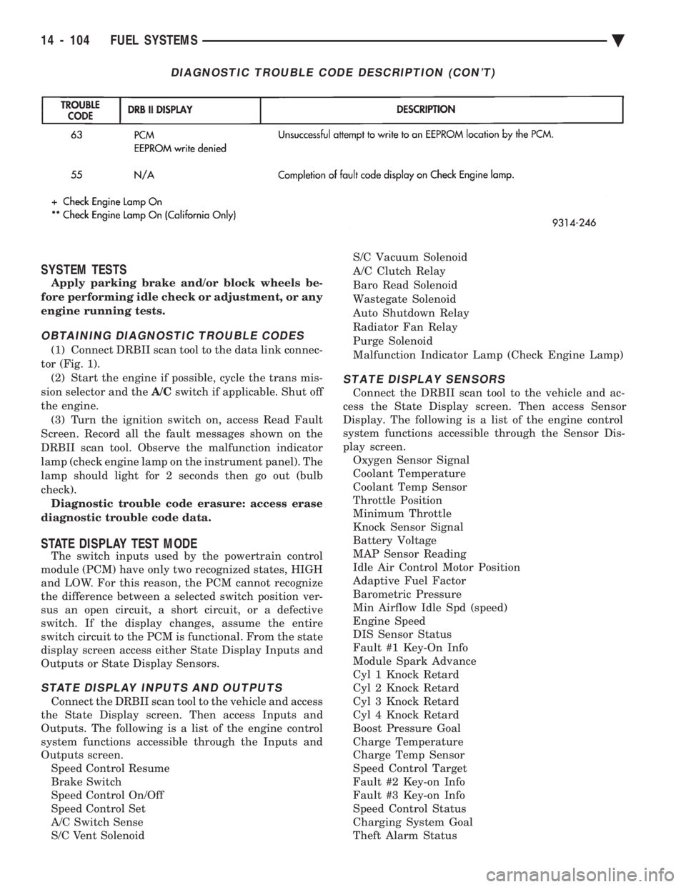
DIAGNOSTIC TROUBLE CODE DESCRIPTION (CON'T)
14 - 104 FUEL SYSTEMS Ä
Page 1874 of 2438
SYSTEM TESTS
WARNING: APPLY PARKING BRAKE AND/OR BLOCK
WHEELS BEFORE PERFORMING ANY TEST ON AN
OPERATING ENGINE.
OBTAINING DIAGNOSTIC TROUBLE CODES
(1) Connect DRBII scan tool to the data link connec-
tor located in the engine compartment near the pow-
ertrain control module (PCM). (2) Start the engine if possible, cycle the transaxle
selector and the A/Cswitch if applicable. Shut off the
engine. (3) Turn the ignition switch on, access Read Fault
Screen. Record all the fault messages shown on the
DRBII scan tool. Observe the malfunction indicator
lamp (Check Engine lamp on the instrument panel).
The lamp should light for 3 seconds then go out (bulb
check). Diagnostic trouble code erasure; access erase
diagnostic trouble code data
STATE DISPLAY TEST MODE
The switch inputs used by the powertrain control
module (PCM) have only two recognized states, HIGH
and LOW. For this reason, the PCM cannot recognize
the difference between a selected switch position ver-
sus an open circuit, a short circuit, or a defective
switch. If the change is displayed, it can be assumed
that the entire switch circuit to the PCM is functional.
From the state display screen access either State
Display Inputs and Outputs or State Display Sensors.
STATE DISPLAY INPUTS AND OUTPUTS
Connect the DRBII scan tool to the vehicle. Access
the State Display screen. Then access Inputs and
Outputs. The following is a list of the engine control
system functions accessible through the Inputs and
Outputs screen. Park/Neutral Switch
Speed Control Resume
Brake Switch
Speed Control On/Off
Speed Control Set
A/C Switch Sense
S/C Vent Solenoid
S/C Vacuum Solenoid
A/C Clutch Relay
EGR Solenoid
Auto Shutdown Relay
Radiator Fan Relay
Purge Solenoid
Torque Converter Clutch Solenoid
Malfunction Indicator Lamp (Check Engine Lamp)
STATE DISPLAY SENSORS
Connect the DRBII scan tool to the vehicle and ac-
cess the State Display screen. Then access Sensor
Display. The following is a list of the engine control
system functions accessible through the Sensor Dis-
play screen. Battery Temperature
Oxygen Sensor Signal
Engine Coolant Temperature
Engine Coolant Temp Sensor
Throttle Position
Minimum Throttle
Battery Voltage
MAP Sensor Reading
Idle Air Control Motor Position
Adaptive Fuel Factor
Barometric Pressure
Min Airflow Idle Speed
Engine Speed
Fault #1 Key-On Info
Module Spark Advance
Speed Control Target
Fault #2 Key-on Info
Fault #3 Key-on Info
Speed Control Status
Speed Control Switch Voltage
Charging System Goal
Theft Alarm Status
Map Sensor Voltage
Vehicle Speed
Oxygen Sensor State
MAP Gauge Reading
Throttle Opening (percentage)
Total Spark Advance
CIRCUIT ACTUATION TEST MODE
The circuit actuation test mode checks for proper
operation of output circuits or devices which the pow-
ertrain control module (PCM) cannot internally rec-
ognize. The PCM can attempt to activate these
outputs and allow an observer to verify proper oper-
ation. Most of the tests provide an audible or visual
indication of device operation (click of relay contacts,
spray fuel, etc.). Except for intermittent conditions, if
a device functions properly during testing, assume
the device, its associated wiring, and driver circuit
working correctly.
OBTAINING CIRCUIT ACTUATION TEST
Connect the DRBII scan tool to the vehicle and ac-
cess the Actuators screen. The following is a list of
the engine control system functions accessible
through Actuators screens. Stop All Tests
Ignition Coil #1
Fuel Injector #1
Fuel Injector #2
Fuel Injector #3
14 - 134 FUEL SYSTEMS Ä
Page 1906 of 2438
S/C Vacuum Solenoid
A/C Clutch Relay
EGR Solenoid
Auto Shutdown Relay
Radiator Fan Relay
Purge Solenoid
Malfunction Indicator Lamp (Check Engine Lamp)
STATE DISPLAY SENSORS
Connect the DRBII scan tool to the vehicle and ac-
cess the State Display screen. Then access Sensor
Display. The following is a list of the engine control
system functions accessible through the Sensor Dis-
play screen. Oxygen Sensor Signal
Engine Coolant Temperature
Engine Coolant Temp Sensor
Throttle Position
Minimum Throttle
Battery Voltage
MAP Sensor Reading
Idle Air Control Motor Position
Adaptive Fuel Factor
Barometric Pressure
Min Airflow Idle Spd (speed)
Engine Speed
DIS Sensor Status
Fault #1 Key-On Info
Module Spark Advance
Speed Control Target
Fault #2 Key-on Info
Fault #3 Key-on Info
Speed Control Status
Speed Control Switch Voltage
Charging System Goal
Theft Alarm Status
Map Sensor Voltage
Vehicle Speed
Oxygen Sensor State
MAP Gauge Reading
Throttle Opening (percentage)
Total Spark Advance
CIRCUIT ACTUATION TEST MODE
The circuit actuation test mode checks for proper
operation of output circuits or devices which the pow-
ertrain control module (PCM) cannot internally rec-
ognize. The PCM can attempt to activate these
outputs and allow an observer to verify proper oper-
ation. Most of the tests provide an audible or visual
indication of device operation (click of relay contacts,
spray fuel, etc.). Except for intermittent conditions, if
a device functions properly during testing, assume
the device, its associated wiring, and driver circuit
working correctly.
OBTAINING CIRCUIT ACTUATION TEST
Connect the DRBII scan tool to the vehicle and ac-
cess the Actuators screen. The following is a list of
the engine control system functions accessible
through Actuators screens. Stop All Tests
Ignition Coil #1
Ignition Coil #2
Ignition Coil #3
Fuel Injector #1
Fuel Injector #2
Fuel Injector #3
Fuel Injector #4
Fuel Injector #5
Fuel Injector #6
Idle Air Control Motor Open/Close
Radiator Fan Relay
A/C Clutch Relay
Auto Shutdown Relay
EVAP Purge Solenoid
S/C Servo Solenoids
Generator Field
EGR Solenoid
All Solenoids/Relays
ASD Fuel System Test
Speed Control Vacuum Solenoid
Speed Control Vent Solenoid
THROTTLE BODY MINIMUM AIR FLOW CHECK
PROCEDURE
(1) Warm engine in Park or Neutral until the cool-
ing fan has cycled on and off at least once. (2) Ensure that all accessories are off.
(3) Shut off engine.
(4) Disconnect the PCV valve hose from the intake
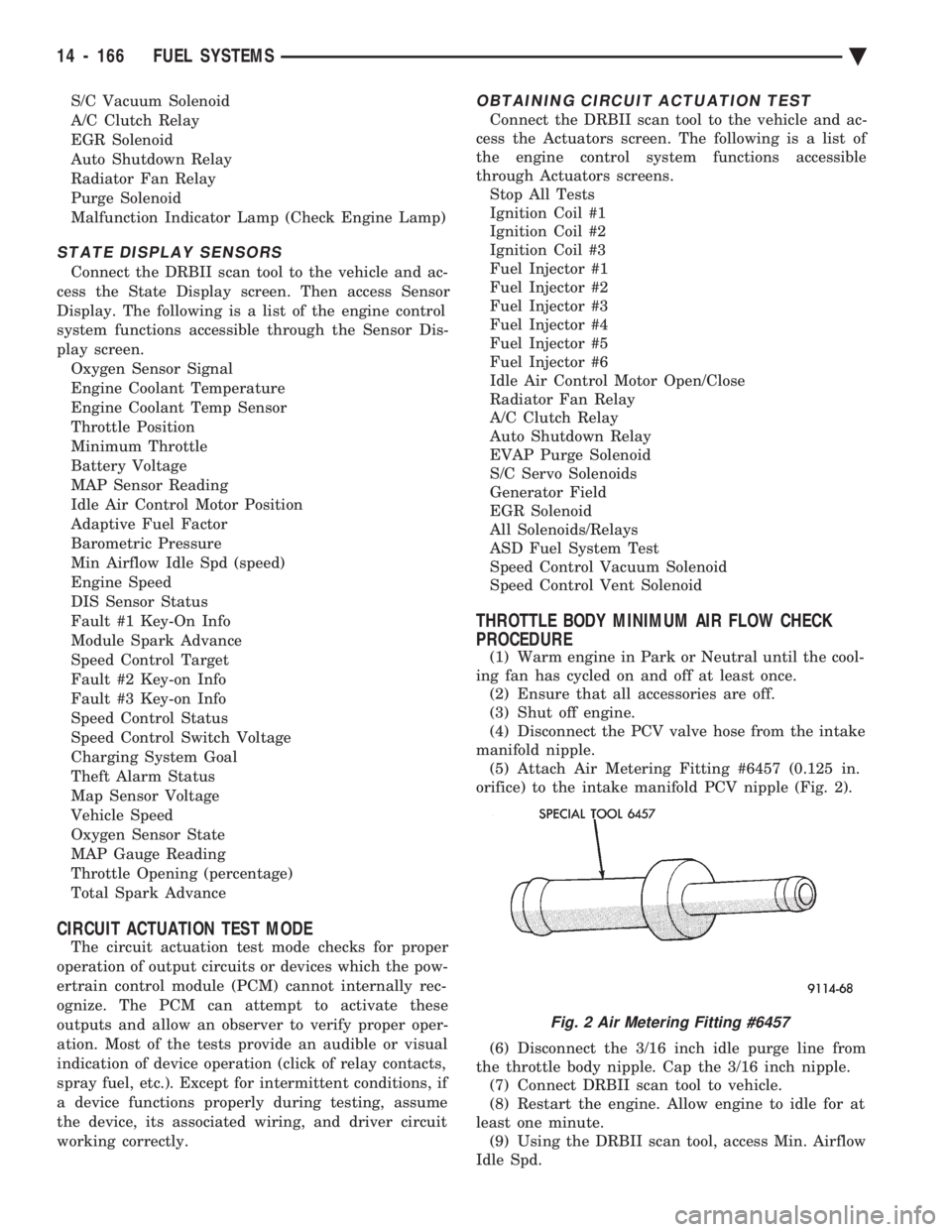
manifold nipple. (5) Attach Air Metering Fitting #6457 (0.125 in.
orifice) to the intake manifold PCV nipple (Fig. 2).
(6) Disconnect the 3/16 inch idle purge line from
the throttle body nipple. Cap the 3/16 inch nipple. (7) Connect DRBII scan tool to vehicle.
(8) Restart the engine. Allow engine to idle for at
least one minute. (9) Using the DRBII scan tool, access Min. Airflow
Idle Spd.
Fig. 2 Air Metering Fitting #6457
14 - 166 FUEL SYSTEMS Ä
Page 2172 of 2438
(6) Separate door from vehicle.
FRONT DOOR INSTALLATION
Reverse the preceding operation. The door should
not require re-alignment. If door does need align-
ment, refer to Front Door Hinge Installation para-
graph in this section.
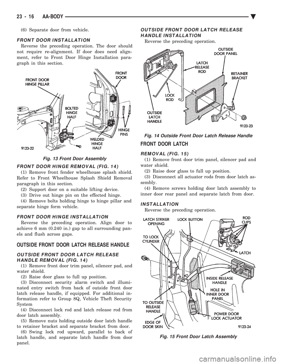
FRONT DOOR HINGE REMOVAL (FIG. 14)
(1) Remove front fender wheelhouse splash shield.
Refer to Front Wheelhouse Splash Shield Removal
paragraph in this section. (2) Support door on a suitable lifting device.
(3) Drive out hinge pin on the effected hinge.
(4) Remove bolts holding hinge to hinge pillar and
separate hinge form vehicle.
FRONT DOOR HINGE INSTALLATION
Reverse the preceding operation. Align door to
achieve 6 mm (0.240 in.) gap to all surrounding pan-
els and flush across gaps.
OUTSIDE FRONT DOOR LATCH RELEASE HANDLE
OUTSIDE FRONT DOOR LATCH RELEASE HANDLE REMOVAL (FIG. 14)
(1) Remove front door trim panel, silencer pad, and
water shield. (2) Raise door glass to full up position.
(3) Disconnect security alarm switch and illumi-
nated entry switch from back of outside front door
latch release handle, if equipped. For additional in-
formation refer to Group 8Q, Vehicle Theft Security
System (4) Disconnect lock rod and latch release rod from
door latch assembly. (5) Remove nuts holding outside door latch handle
to retainer bracket and separate bracket from door. (6) Swing lock rod upward, parallel to back of
latch handle, and separate latch handle from door
panel.
OUTSIDE FRONT DOOR LATCH RELEASE
HANDLE INSTALLATION
Reverse the preceding operation.
FRONT DOOR LATCH
REMOVAL (FIG. 15)
(1) Remove front door trim panel, silencer pad and
water shield. (2) Raise door glass to full up position.
(3) Disconnect all actuator rods from door latch as-
sembly. (4) Remove screws holding door latch assembly to
inner door rear panel and separate latch from door.
INSTALLATION
Reverse the preceding operation.
Fig. 13 Front Door Assembly
Fig. 14 Outside Front Door Latch Release Handle
Fig. 15 Front Door Latch Assembly
23 - 16 AA-BODY Ä
Page 2214 of 2438
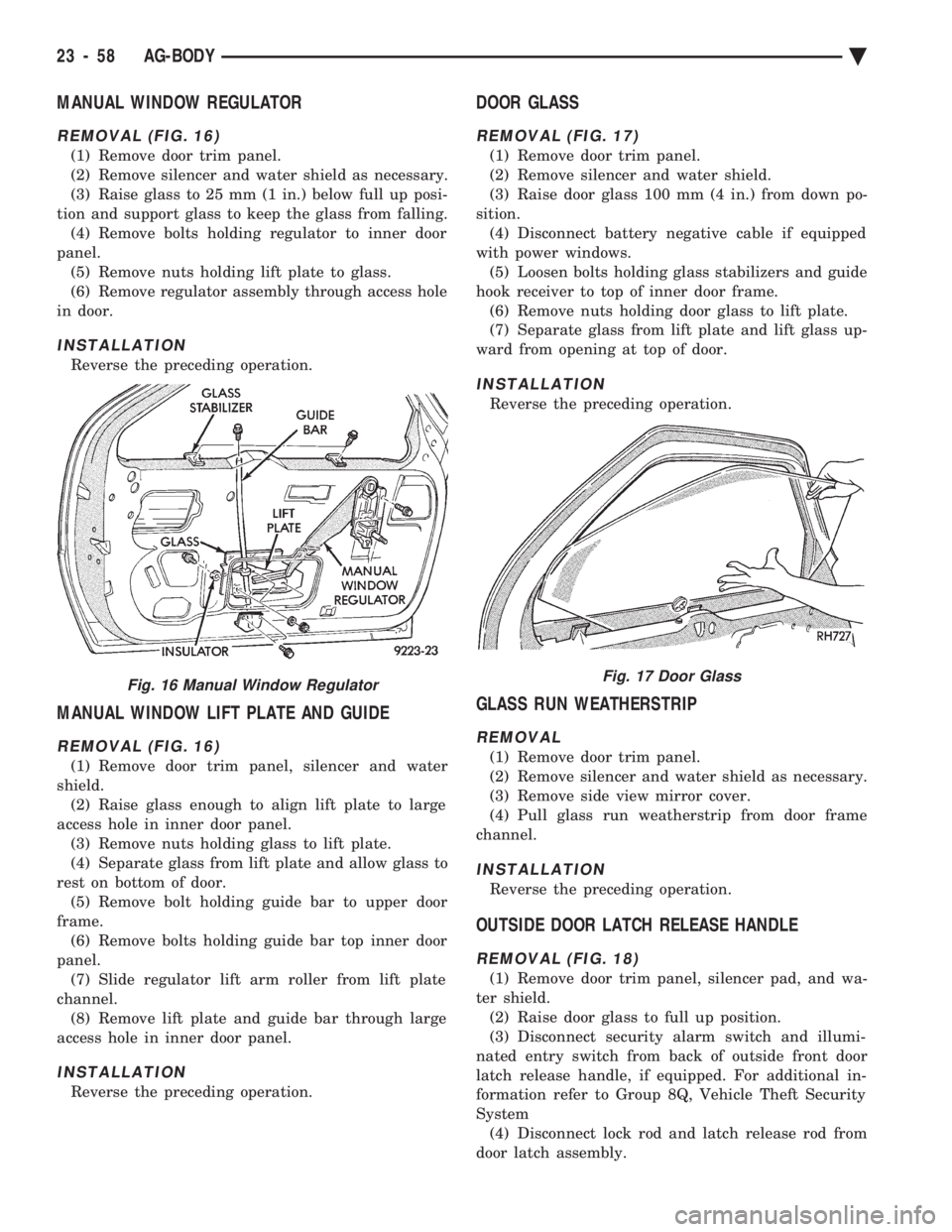
MANUAL WINDOW REGULATOR
REMOVAL (FIG. 16)
(1) Remove door trim panel.
(2) Remove silencer and water shield as necessary.
(3) Raise glass to 25 mm (1 in.) below full up posi-
tion and support glass to keep the glass from falling. (4) Remove bolts holding regulator to inner door
panel. (5) Remove nuts holding lift plate to glass.
(6) Remove regulator assembly through access hole
in door.
INSTALLATION
Reverse the preceding operation.
MANUAL WINDOW LIFT PLATE AND GUIDE
REMOVAL (FIG. 16)
(1) Remove door trim panel, silencer and water
shield. (2) Raise glass enough to align lift plate to large
access hole in inner door panel. (3) Remove nuts holding glass to lift plate.
(4) Separate glass from lift plate and allow glass to
rest on bottom of door. (5) Remove bolt holding guide bar to upper door
frame. (6) Remove bolts holding guide bar top inner door
panel. (7) Slide regulator lift arm roller from lift plate
channel. (8) Remove lift plate and guide bar through large
access hole in inner door panel.
INSTALLATION
Reverse the preceding operation.
DOOR GLASS
REMOVAL (FIG. 17)
(1) Remove door trim panel.
(2) Remove silencer and water shield.
(3) Raise door glass 100 mm (4 in.) from down po-
sition. (4) Disconnect battery negative cable if equipped
with power windows. (5) Loosen bolts holding glass stabilizers and guide
hook receiver to top of inner door frame. (6) Remove nuts holding door glass to lift plate.
(7) Separate glass from lift plate and lift glass up-
ward from opening at top of door.
INSTALLATION
Reverse the preceding operation.
GLASS RUN WEATHERSTRIP
REMOVAL
(1) Remove door trim panel.
(2) Remove silencer and water shield as necessary.
(3) Remove side view mirror cover.
(4) Pull glass run weatherstrip from door frame
channel.
INSTALLATION
Reverse the preceding operation.
OUTSIDE DOOR LATCH RELEASE HANDLE
REMOVAL (FIG. 18)
(1) Remove door trim panel, silencer pad, and wa-
ter shield. (2) Raise door glass to full up position.
(3) Disconnect security alarm switch and illumi-
nated entry switch from back of outside front door
latch release handle, if equipped. For additional in-
formation refer to Group 8Q, Vehicle Theft Security
System (4) Disconnect lock rod and latch release rod from
door latch assembly.
Fig. 16 Manual Window RegulatorFig. 17 Door Glass
23 - 58 AG-BODY Ä
Page 2232 of 2438
DOOR GLASS
REMOVAL
(1) Remove door trim panel.
(2) Remove silencer and water shield.
(3) Raise door glass 100 mm (4 in.) from down po-
sition. (4) Disconnect battery negative cable if equipped
with power windows. (5) Loosen bolts holding glass stabilizers and guide
hook receiver to top of inner door frame. (6) Remove nuts holding door glass to lift plate.
(7) Separate glass from lift plate and lift glass up-
ward from opening at top of door.
INSTALLATION
Reverse the preceding operation.
DOOR GLASS LIFT PLATE AND GUIDE POST
REMOVAL
(1) Remove door trim panel.
(2) Remove silencer and water shield.
(3) Raise door glass 100 mm (4 in.) from down po-
sition. (4) Disconnect battery negative cable if equipped
with power windows. (5) Remove nuts holding door glass to lift plate
and separate glass from lift plate. Allow glass to
slide downward to the bottom of door. (6) Remove bolts (nuts on AJ-27 body) holding
guide post to inner door panel. (7) Separate lift plate channel from regulator lift
roller. (8) Remove lift plate and guide assemble from door
through access hole in inner door panel.
INSTALLATION
Reverse the preceding operation.
GLASS RUN WEATHERSTRIPÐAJ-21 BODY
REMOVAL
(1) Remove door trim panel.
(2) Remove silencer and water shield as necessary.
(3) Remove side view mirror cover.
(4) Pull glass run weatherstrip from door frame
channel.
INSTALLATION
Reverse the preceding operation.
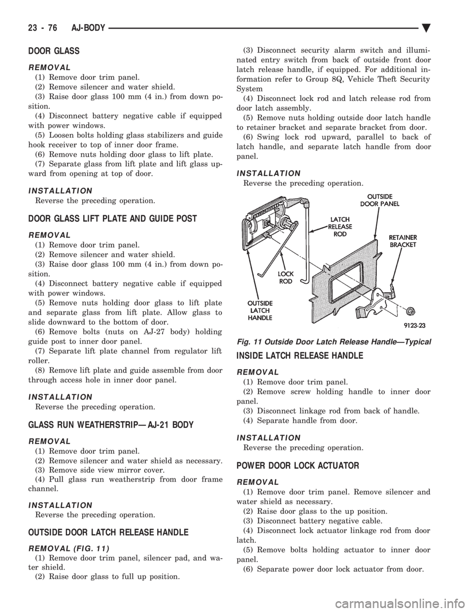
OUTSIDE DOOR LATCH RELEASE HANDLE
REMOVAL (FIG. 11)
(1) Remove door trim panel, silencer pad, and wa-
ter shield. (2) Raise door glass to full up position. (3) Disconnect security alarm switch and illumi-
nated entry switch from back of outside front door
latch release handle, if equipped. For additional in-
formation refer to Group 8Q, Vehicle Theft Security
System (4) Disconnect lock rod and latch release rod from
door latch assembly. (5) Remove nuts holding outside door latch handle
to retainer bracket and separate bracket from door. (6) Swing lock rod upward, parallel to back of
latch handle, and separate latch handle from door
panel.
INSTALLATION
Reverse the preceding operation.
INSIDE LATCH RELEASE HANDLE
REMOVAL
(1) Remove door trim panel.
(2) Remove screw holding handle to inner door
panel. (3) Disconnect linkage rod from back of handle.
(4) Separate handle from door.
INSTALLATION
Reverse the preceding operation.
POWER DOOR LOCK ACTUATOR
REMOVAL
(1) Remove door trim panel. Remove silencer and
water shield as necessary. (2) Raise door glass to the up position.
(3) Disconnect battery negative cable.
(4) Disconnect lock actuator linkage rod from door
latch. (5) Remove bolts holding actuator to inner door
panel. (6) Separate power door lock actuator from door.
Fig. 11 Outside Door Latch Release HandleÐTypical
23 - 76 AJ-BODY Ä
Page 2257 of 2438
FRONT DOOR HINGE INSTALLATION
Reverse the preceding operation. Align door to
achieve 6 mm (0.240 in.) gap to all surrounding pan-
els and flush across gaps.
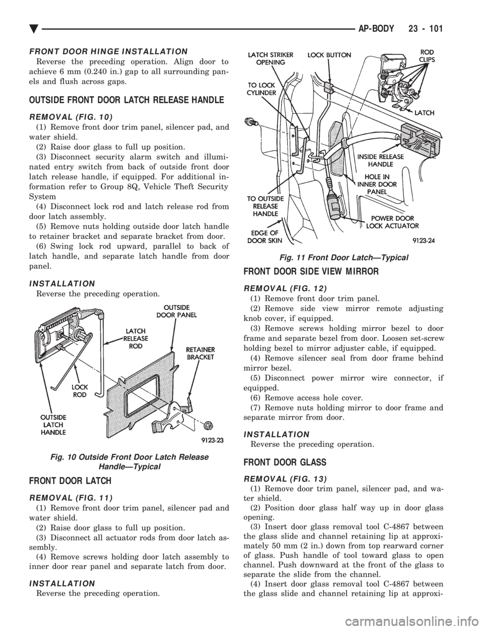
OUTSIDE FRONT DOOR LATCH RELEASE HANDLE
REMOVAL (FIG. 10)
(1) Remove front door trim panel, silencer pad, and
water shield. (2) Raise door glass to full up position.
(3) Disconnect security alarm switch and illumi-
nated entry switch from back of outside front door
latch release handle, if equipped. For additional in-
formation refer to Group 8Q, Vehicle Theft Security
System (4) Disconnect lock rod and latch release rod from
door latch assembly. (5) Remove nuts holding outside door latch handle
to retainer bracket and separate bracket from door. (6) Swing lock rod upward, parallel to back of
latch handle, and separate latch handle from door
panel.
INSTALLATION
Reverse the preceding operation.
FRONT DOOR LATCH
REMOVAL (FIG. 11)
(1) Remove front door trim panel, silencer pad and
water shield. (2) Raise door glass to full up position.
(3) Disconnect all actuator rods from door latch as-
sembly. (4) Remove screws holding door latch assembly to
inner door rear panel and separate latch from door.
INSTALLATION
Reverse the preceding operation.
FRONT DOOR SIDE VIEW MIRROR
REMOVAL (FIG. 12)
(1) Remove front door trim panel.
(2) Remove side view mirror remote adjusting
knob cover, if equipped. (3) Remove screws holding mirror bezel to door
frame and separate bezel from door. Loosen set-screw
holding bezel to mirror adjuster cable, if equipped. (4) Remove silencer seal from door frame behind
mirror bezel. (5) Disconnect power mirror wire connector, if
equipped. (6) Remove access hole cover.
(7) Remove nuts holding mirror to door frame and
separate mirror from door.
INSTALLATION
Reverse the preceding operation.
FRONT DOOR GLASS
REMOVAL (FIG. 13)
(1) Remove door trim panel, silencer pad, and wa-
ter shield. (2) Position door glass half way up in door glass
opening. (3) Insert door glass removal tool C-4867 between
the glass slide and channel retaining lip at approxi-
mately 50 mm (2 in.) down from top rearward corner
of glass. Push handle of tool toward glass to open
channel. Push downward at the front of the glass to
separate the slide from the channel. (4) Insert door glass removal tool C-4867 between
the glass slide and channel retaining lip at approxi-
Fig. 10 Outside Front Door Latch Release HandleÐTypical
Fig. 11 Front Door LatchÐTypical
Ä AP-BODY 23 - 101
Page 2367 of 2438
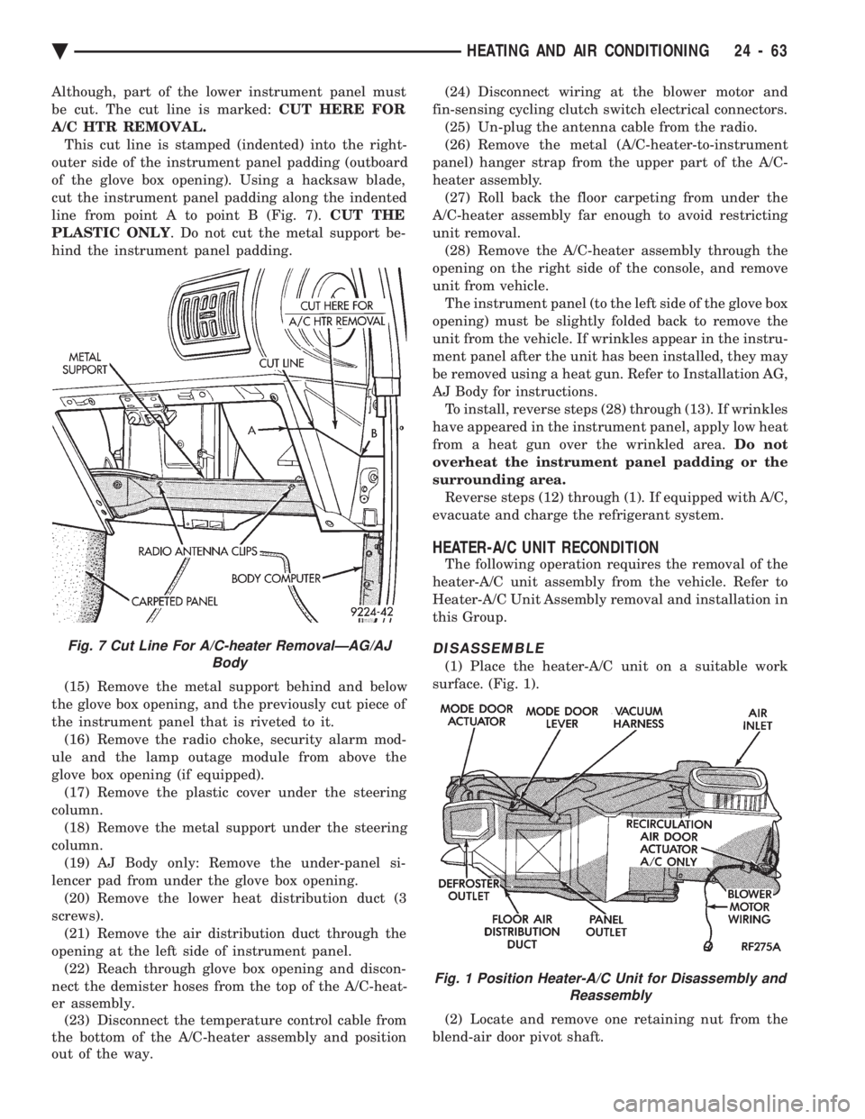
Although, part of the lower instrument panel must
be cut. The cut line is marked: CUT HERE FOR
A/C HTR REMOVAL. This cut line is stamped (indented) into the right-
outer side of the instrument panel padding (outboard
of the glove box opening). Using a hacksaw blade,
cut the instrument panel padding along the indented
line from point A to point B (Fig. 7). CUT THE
PLASTIC ONLY . Do not cut the metal support be-
hind the instrument panel padding.
(15) Remove the metal support behind and below
the glove box opening, and the previously cut piece of
the instrument panel that is riveted to it. (16) Remove the radio choke, security alarm mod-
ule and the lamp outage module from above the
glove box opening (if equipped). (17) Remove the plastic cover under the steering
column. (18) Remove the metal support under the steering
column. (19) AJ Body only: Remove the under-panel si-
lencer pad from under the glove box opening. (20) Remove the lower heat distribution duct (3
screws). (21) Remove the air distribution duct through the
opening at the left side of instrument panel. (22) Reach through glove box opening and discon-
nect the demister hoses from the top of the A/C-heat-
er assembly. (23) Disconnect the temperature control cable from
the bottom of the A/C-heater assembly and position
out of the way. (24) Disconnect wiring at the blower motor and
fin-sensing cycling clutch switch electrical connectors. (25) Un-plug the antenna cable from the radio.
(26) Remove the metal (A/C-heater-to-instrument
panel) hanger strap from the upper part of the A/C-
heater assembly. (27) Roll back the floor carpeting from under the
A/C-heater assembly far enough to avoid restricting
unit removal. (28) Remove the A/C-heater assembly through the
opening on the right side of the console, and remove
unit from vehicle. The instrument panel (to the left side of the glove box
opening) must be slightly folded back to remove the
unit from the vehicle. If wrinkles appear in the instru-
ment panel after the unit has been installed, they may
be removed using a heat gun. Refer to Installation AG,
AJ Body for instructions. To install, reverse steps (28) through (13). If wrinkles
have appeared in the instrument panel, apply low heat
from a heat gun over the wrinkled area. Do not
overheat the instrument panel padding or the
surrounding area. Reverse steps (12) through (1). If equipped with A/C,
evacuate and charge the refrigerant system.
HEATER-A/C UNIT RECONDITION
The following operation requires the removal of the
heater-A/C unit assembly from the vehicle. Refer to
Heater-A/C Unit Assembly removal and installation in
this Group.
DISASSEMBLE
(1) Place the heater-A/C unit on a suitable work
surface. (Fig. 1).
(2) Locate and remove one retaining nut from the
blend-air door pivot shaft.
Fig. 7 Cut Line For A/C-heater RemovalÐAG/AJ Body
Fig. 1 Position Heater-A/C Unit for Disassembly andReassembly
Ä HEATING AND AIR CONDITIONING 24 - 63