1993 CHEVROLET PLYMOUTH ACCLAIM relay
[x] Cancel search: relayPage 2169 of 2438
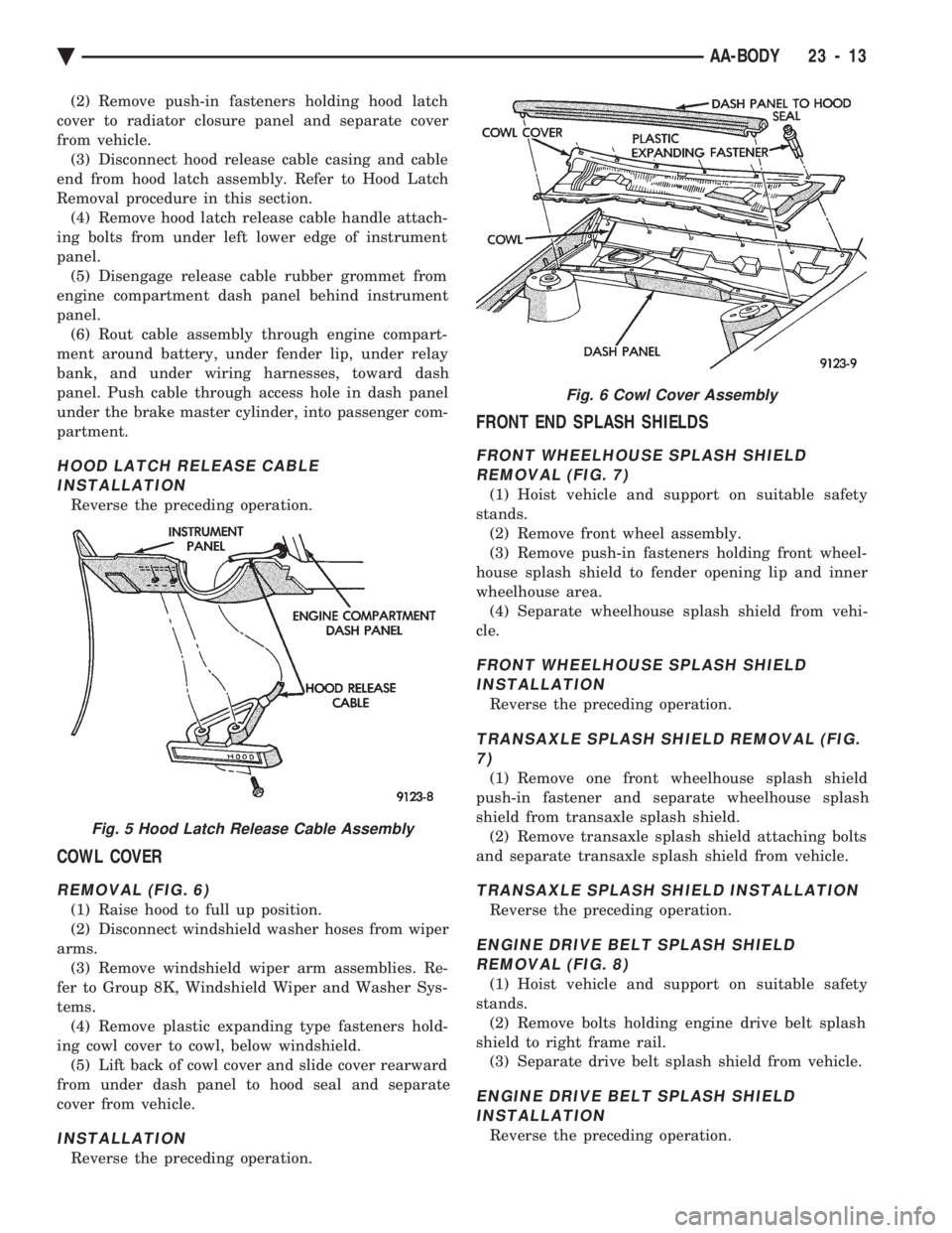
(2) Remove push-in fasteners holding hood latch
cover to radiator closure panel and separate cover
from vehicle. (3) Disconnect hood release cable casing and cable
end from hood latch assembly. Refer to Hood Latch
Removal procedure in this section. (4) Remove hood latch release cable handle attach-
ing bolts from under left lower edge of instrument
panel. (5) Disengage release cable rubber grommet from
engine compartment dash panel behind instrument
panel. (6) Rout cable assembly through engine compart-
ment around battery, under fender lip, under relay
bank, and under wiring harnesses, toward dash
panel. Push cable through access hole in dash panel
under the brake master cylinder, into passenger com-
partment.
HOOD LATCH RELEASE CABLE INSTALLATION
Reverse the preceding operation.
COWL COVER
REMOVAL (FIG. 6)
(1) Raise hood to full up position.
(2) Disconnect windshield washer hoses from wiper
arms. (3) Remove windshield wiper arm assemblies. Re-
fer to Group 8K, Windshield Wiper and Washer Sys-
tems. (4) Remove plastic expanding type fasteners hold-
ing cowl cover to cowl, below windshield. (5) Lift back of cowl cover and slide cover rearward
from under dash panel to hood seal and separate
cover from vehicle.
INSTALLATION
Reverse the preceding operation.
FRONT END SPLASH SHIELDS
FRONT WHEELHOUSE SPLASH SHIELD REMOVAL (FIG. 7)
(1) Hoist vehicle and support on suitable safety
stands. (2) Remove front wheel assembly.
(3) Remove push-in fasteners holding front wheel-
house splash shield to fender opening lip and inner
wheelhouse area. (4) Separate wheelhouse splash shield from vehi-
cle.
FRONT WHEELHOUSE SPLASH SHIELD INSTALLATION
Reverse the preceding operation.
TRANSAXLE SPLASH SHIELD REMOVAL (FIG.7)
(1) Remove one front wheelhouse splash shield
push-in fastener and separate wheelhouse splash
shield from transaxle splash shield. (2) Remove transaxle splash shield attaching bolts
and separate transaxle splash shield from vehicle.
TRANSAXLE SPLASH SHIELD INSTALLATION
Reverse the preceding operation.
ENGINE DRIVE BELT SPLASH SHIELD REMOVAL (FIG. 8)
(1) Hoist vehicle and support on suitable safety
stands. (2) Remove bolts holding engine drive belt splash
shield to right frame rail. (3) Separate drive belt splash shield from vehicle.
ENGINE DRIVE BELT SPLASH SHIELDINSTALLATION
Reverse the preceding operation.
Fig. 5 Hood Latch Release Cable Assembly
Fig. 6 Cowl Cover Assembly
Ä AA-BODY 23 - 13
Page 2195 of 2438
ing hood, align all marks and secure bolts. The hood
should be aligned to 4 mm (0.160 in.) gap to the front
fenders and flush across the top surfaces along fend-
ers.(4) Remove the top hood to hinge bolts and loosen
the bottom bolts until they can be removed by hand. (5) With assistance of a helper at the opposite side
of the vehicle to support the hood, remove the bottom
hood to hinge bolts. Separate the hood from the ve-
hicle.
HOOD INSTALLATION
Reverse the preceding operation.
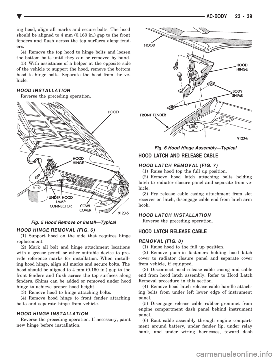
HOOD HINGE REMOVAL (FIG. 6)
(1) Support hood on the side that requires hinge
replacement. (2) Mark all bolt and hinge attachment locations
with a grease pencil or other suitable device to pro-
vide reference marks for installation. When install-
ing hood hinge, align all marks and secure bolts. The
hood should be aligned to 4 mm (0.160 in.) gap to the
front fenders and flush across the top surfaces along
fenders. Shims can be added or removed under hood
hinge to achieve proper hood height. (3) Remove hood to hinge attaching bolts.
(4) Remove hood hinge to front fender attaching
bolts and separate hinge from vehicle.
HOOD HINGE INSTALLATION
Reverse the preceding operation. If necessary, paint
new hinge before installation.
HOOD LATCH AND RELEASE CABLE
HOOD LATCH REMOVAL (FIG. 7)
(1) Raise hood top the full up position.
(2) Remove hood latch attaching bolts holding
latch to radiator closure panel and separate from ve-
hicle. (3) Pry release cable casing attachment from slot
receiver on latch, disengage cable end from latch arm
hook.
HOOD LATCH INSTALLATION
Reverse the preceding operation.
HOOD LATCH RELEASE CABLE
REMOVAL (FIG. 8)
(1) Raise hood to the full up position.
(2) Remove push-in fasteners holding hood latch
cover to radiator closure panel and separate cover
from vehicle, if equipped. (3) Disconnect hood release cable casing and cable
end from hood latch assembly. Refer to Hood Latch
Removal procedure in this section. (4) Remove hood latch release cable handle attach-
ing bolts from under left lower edge of instrument
panel. (5) Disengage release cable rubber grommet from
engine compartment dash panel behind instrument
panel. (6) Rout cable assembly through engine compart-
ment around battery, under fender lip, under relay
bank, and under wiring harnesses, toward dash
Fig. 5 Hood Remove or InstallÐTypical
Fig. 6 Hood Hinge AssemblyÐTypical
Ä AC-BODY 23 - 39
Page 2229 of 2438
(4) Remove hood latch release cable handle attach-
ing bolts from under left lower edge of instrument
panel. (5) Disengage release cable rubber grommet from
engine compartment dash panel behind instrument
panel. (6) Rout cable assembly through engine compart-
ment around battery, under fender lip, under relay
bank, and under wiring harnesses, toward dash panel. Push cable through access hole in dash panel
under the brake master cylinder, into passenger com-
partment.
HOOD LATCH RELEASE CABLE INSTALLATION
Reverse the preceding operation.
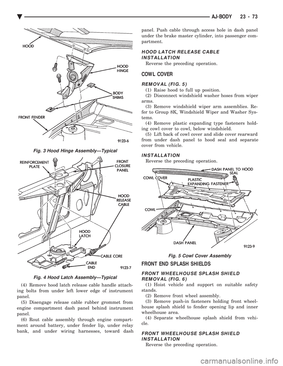
COWL COVER
REMOVAL (FIG. 5)
(1) Raise hood to full up position.
(2) Disconnect windshield washer hoses from wiper
arms. (3) Remove windshield wiper arm assemblies. Re-
fer to Group 8K, Windshield Wiper and Washer Sys-
tems. (4) Remove plastic expanding type fasteners hold-
ing cowl cover to cowl, below windshield. (5) Lift back of cowl cover and slide cover rearward
from under dash panel to hood seal and separate
cover from vehicle.
INSTALLATION
Reverse the preceding operation.
FRONT END SPLASH SHIELDS
FRONT WHEELHOUSE SPLASH SHIELD REMOVAL (FIG. 6)
(1) Hoist vehicle and support on suitable safety
stands. (2) Remove front wheel assembly.
(3) Remove push-in fasteners holding front wheel-
house splash shield to fender opening lip and inner
wheelhouse area. (4) Separate wheelhouse splash shield from vehi-
cle.
FRONT WHEELHOUSE SPLASH SHIELD INSTALLATION
Reverse the preceding operation.
Fig. 3 Hood Hinge AssemblyÐTypical
Fig. 4 Hood Latch AssemblyÐTypical
Fig. 5 Cowl Cover Assembly
Ä AJ-BODY 23 - 73
Page 2251 of 2438
HYDRAULIC SYSTEMS
The power convertible top hydraulic system con-
sists of;
² Two hydraulic cylinders
² Hydraulic lines
² Electric hydraulic pump and reservoir
² Dual relays
HYDRAULIC SYSTEM TESTS
The convertible top will raise slowly or make ab-
normal noise if the hydraulic fluid level is low. (1) Remove sling well and floor cover.
(2) With the top up and latched, remove the reser-
voir fill plug. (3) Visually inspect fluid level. If low, inspect for
leak in hydraulic system. (4) Repair or replace components, as necessary.
(5) Fill reservoir with Dexron tII, Type A, auto-
matic transmission fluid to the bottom of the fill
hole. (6) Replace fill plug and lower top.
(7) Raise top and verify fluid level.
(8) Install sling well and floor cover.
HYDRAULIC PUMP ASSEMBLY
HYDRAULIC PUMP REMOVAL (FIG. 13)
(1) Disconnect battery negative cable.
(2) Remove sling well and floor cover from behind
rear seat. (3) Disconnect pump wire connector and ground
connection. (4) Disconnect hydraulic lines from pump.
(5) Remove motor pump assembly from vehicle.
The rubber mounts are pressed and locked into the
mounting bracket. Pull up motor assembly to re-
move.
HYDRAULIC PUMP INSTALLATION
Reverse the preceding operation
HYDRAULIC CYLINDER
HYDRAULIC CYLINDER REMOVAL
(1) Disconnect battery negative cable.
(2) Remove interior trim as necessary to gain ac-
cess to hydraulic cylinders. (3) Remove cylinder mounting bracket and nut.
(4) Remove pivot bolt holding cylinder shaft to top
linkage. (5) Disconnect hydraulic lines from the cylinder.
(6) Remove cylinder from vehicle.
HYDRAULIC CYLINDER INSTALLATION
Reverse the preceding operation, and verify each
hydraulic seal is in place when connecting the line to
the cylinder. Replace seal if damaged.
HYDRAULIC PUMP LINE SEALS
HYDRAULIC PUMP LINE SEALS REMOVAL
(1) Disconnect battery negative cable.
(2) Disconnect hydraulic lines from pump and re-
move seals.
HYDRAULIC PUMP LINE SEALS INSTALLATION
Reverse the preceding operation.
HYDRAULIC CYLINDER LINE SEALS
REMOVAL
(1) Remove hydraulic cylinder to gain access to hy-
draulic line connections. (2) Disconnect hydraulic lines from cylinder and
remove seals.
INSTALLATION
Reverse the preceding operation.
Ä AJ/27-BODY 23 - 95
Page 2254 of 2438
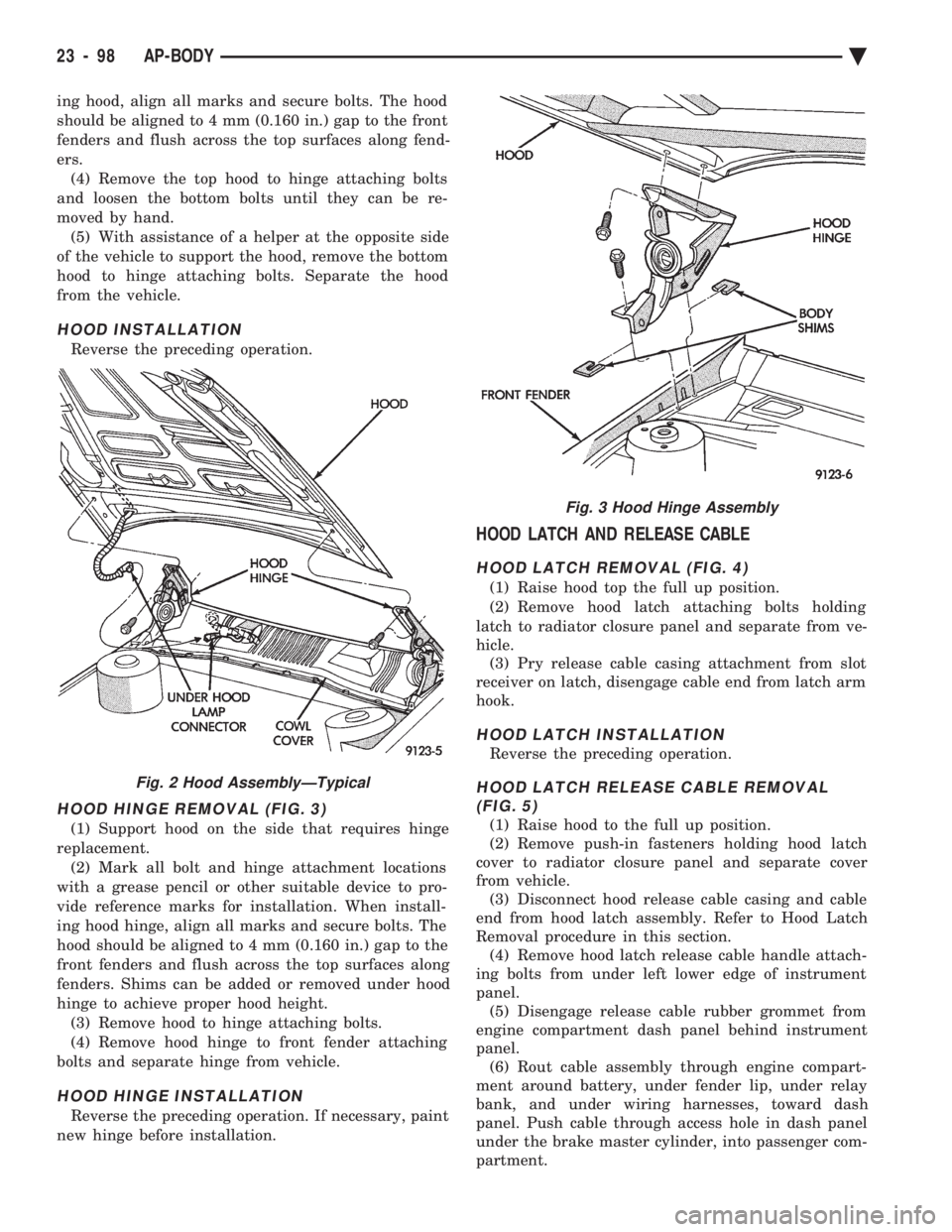
ing hood, align all marks and secure bolts. The hood
should be aligned to 4 mm (0.160 in.) gap to the front
fenders and flush across the top surfaces along fend-
ers.(4) Remove the top hood to hinge attaching bolts
and loosen the bottom bolts until they can be re-
moved by hand. (5) With assistance of a helper at the opposite side
of the vehicle to support the hood, remove the bottom
hood to hinge attaching bolts. Separate the hood
from the vehicle.
HOOD INSTALLATION
Reverse the preceding operation.
HOOD HINGE REMOVAL (FIG. 3)
(1) Support hood on the side that requires hinge
replacement. (2) Mark all bolt and hinge attachment locations
with a grease pencil or other suitable device to pro-
vide reference marks for installation. When install-
ing hood hinge, align all marks and secure bolts. The
hood should be aligned to 4 mm (0.160 in.) gap to the
front fenders and flush across the top surfaces along
fenders. Shims can be added or removed under hood
hinge to achieve proper hood height. (3) Remove hood to hinge attaching bolts.
(4) Remove hood hinge to front fender attaching
bolts and separate hinge from vehicle.
HOOD HINGE INSTALLATION
Reverse the preceding operation. If necessary, paint
new hinge before installation.
HOOD LATCH AND RELEASE CABLE
HOOD LATCH REMOVAL (FIG. 4)
(1) Raise hood top the full up position.
(2) Remove hood latch attaching bolts holding
latch to radiator closure panel and separate from ve-
hicle. (3) Pry release cable casing attachment from slot
receiver on latch, disengage cable end from latch arm
hook.
HOOD LATCH INSTALLATION
Reverse the preceding operation.
HOOD LATCH RELEASE CABLE REMOVAL (FIG. 5)
(1) Raise hood to the full up position.
(2) Remove push-in fasteners holding hood latch
cover to radiator closure panel and separate cover
from vehicle. (3) Disconnect hood release cable casing and cable
end from hood latch assembly. Refer to Hood Latch
Removal procedure in this section. (4) Remove hood latch release cable handle attach-
ing bolts from under left lower edge of instrument
panel. (5) Disengage release cable rubber grommet from
engine compartment dash panel behind instrument
panel. (6) Rout cable assembly through engine compart-
ment around battery, under fender lip, under relay
bank, and under wiring harnesses, toward dash
panel. Push cable through access hole in dash panel
under the brake master cylinder, into passenger com-
partment.
Fig. 2 Hood AssemblyÐTypical
Fig. 3 Hood Hinge Assembly
23 - 98 AP-BODY Ä
Page 2292 of 2438
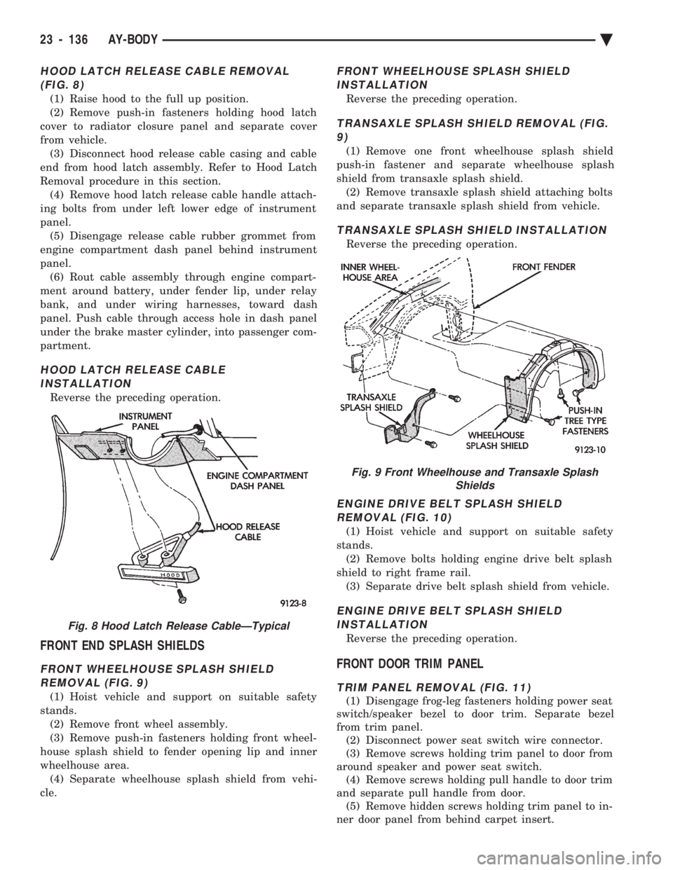
HOOD LATCH RELEASE CABLE REMOVAL (FIG. 8)
(1) Raise hood to the full up position.
(2) Remove push-in fasteners holding hood latch
cover to radiator closure panel and separate cover
from vehicle. (3) Disconnect hood release cable casing and cable
end from hood latch assembly. Refer to Hood Latch
Removal procedure in this section. (4) Remove hood latch release cable handle attach-
ing bolts from under left lower edge of instrument
panel. (5) Disengage release cable rubber grommet from
engine compartment dash panel behind instrument
panel. (6) Rout cable assembly through engine compart-
ment around battery, under fender lip, under relay
bank, and under wiring harnesses, toward dash
panel. Push cable through access hole in dash panel
under the brake master cylinder, into passenger com-
partment.
HOOD LATCH RELEASE CABLE INSTALLATION
Reverse the preceding operation.
FRONT END SPLASH SHIELDS
FRONT WHEELHOUSE SPLASH SHIELDREMOVAL (FIG. 9)
(1) Hoist vehicle and support on suitable safety
stands. (2) Remove front wheel assembly.
(3) Remove push-in fasteners holding front wheel-
house splash shield to fender opening lip and inner
wheelhouse area. (4) Separate wheelhouse splash shield from vehi-
cle.
FRONT WHEELHOUSE SPLASH SHIELD INSTALLATION
Reverse the preceding operation.
TRANSAXLE SPLASH SHIELD REMOVAL (FIG.9)
(1) Remove one front wheelhouse splash shield
push-in fastener and separate wheelhouse splash
shield from transaxle splash shield. (2) Remove transaxle splash shield attaching bolts
and separate transaxle splash shield from vehicle.
TRANSAXLE SPLASH SHIELD INSTALLATION
Reverse the preceding operation.
ENGINE DRIVE BELT SPLASH SHIELD REMOVAL (FIG. 10)
(1) Hoist vehicle and support on suitable safety
stands. (2) Remove bolts holding engine drive belt splash
shield to right frame rail. (3) Separate drive belt splash shield from vehicle.
ENGINE DRIVE BELT SPLASH SHIELDINSTALLATION
Reverse the preceding operation.
FRONT DOOR TRIM PANEL
TRIM PANEL REMOVAL (FIG. 11)
(1) Disengage frog-leg fasteners holding power seat
switch/speaker bezel to door trim. Separate bezel
from trim panel. (2) Disconnect power seat switch wire connector.
(3) Remove screws holding trim panel to door from
around speaker and power seat switch. (4) Remove screws holding pull handle to door trim
and separate pull handle from door. (5) Remove hidden screws holding trim panel to in-
ner door panel from behind carpet insert.
Fig. 8 Hood Latch Release CableÐTypical
Fig. 9 Front Wheelhouse and Transaxle Splash Shields
23 - 136 AY-BODY Ä
Page 2358 of 2438
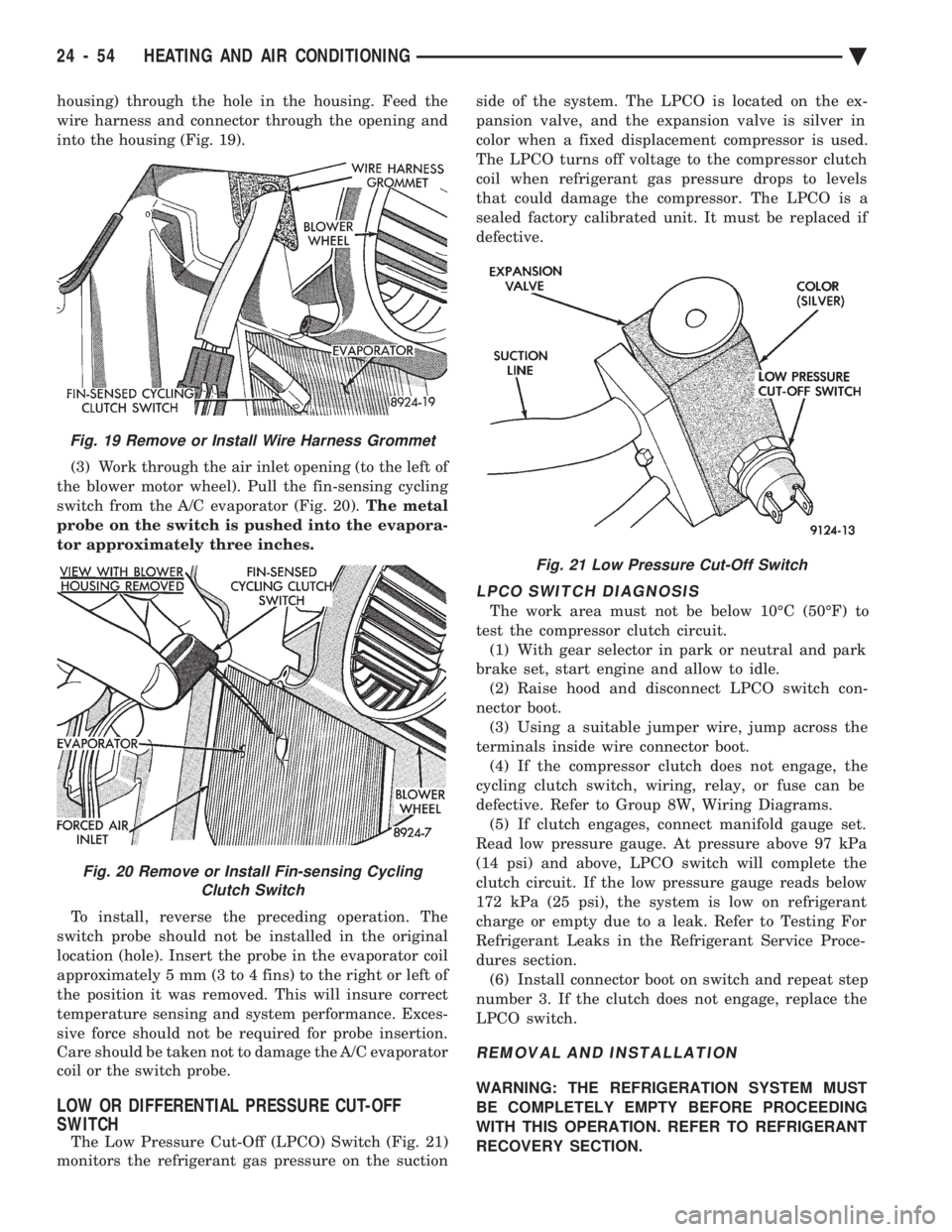
housing) through the hole in the housing. Feed the
wire harness and connector through the opening and
into the housing (Fig. 19). (3) Work through the air inlet opening (to the left of
the blower motor wheel). Pull the fin-sensing cycling
switch from the A/C evaporator (Fig. 20). The metal
probe on the switch is pushed into the evapora-
tor approximately three inches.
To install, reverse the preceding operation. The
switch probe should not be installed in the original
location (hole). Insert the probe in the evaporator coil
approximately 5 mm (3 to 4 fins) to the right or left of
the position it was removed. This will insure correct
temperature sensing and system performance. Exces-
sive force should not be required for probe insertion.
Care should be taken not to damage the A/C evaporator
coil or the switch probe.
LOW OR DIFFERENTIAL PRESSURE CUT-OFF
SWITCH
The Low Pressure Cut-Off (LPCO) Switch (Fig. 21)
monitors the refrigerant gas pressure on the suction side of the system. The LPCO is located on the ex-
pansion valve, and the expansion valve is silver in
color when a fixed displacement compressor is used.
The LPCO turns off voltage to the compressor clutch
coil when refrigerant gas pressure drops to levels
that could damage the compressor. The LPCO is a
sealed factory calibrated unit. It must be replaced if
defective.
LPCO SWITCH DIAGNOSIS
The work area must not be below 10ÉC (50ÉF) to
test the compressor clutch circuit. (1) With gear selector in park or neutral and park
brake set, start engine and allow to idle. (2) Raise hood and disconnect LPCO switch con-
nector boot. (3) Using a suitable jumper wire, jump across the
terminals inside wire connector boot. (4) If the compressor clutch does not engage, the
cycling clutch switch, wiring, relay, or fuse can be
defective. Refer to Group 8W, Wiring Diagrams. (5) If clutch engages, connect manifold gauge set.
Read low pressure gauge. At pressure above 97 kPa
(14 psi) and above, LPCO switch will complete the
clutch circuit. If the low pressure gauge reads below
172 kPa (25 psi), the system is low on refrigerant
charge or empty due to a leak. Refer to Testing For
Refrigerant Leaks in the Refrigerant Service Proce-
dures section. (6) Install connector boot on switch and repeat step
number 3. If the clutch does not engage, replace the
LPCO switch.
REMOVAL AND INSTALLATION
WARNING: THE REFRIGERATION SYSTEM MUST
BE COMPLETELY EMPTY BEFORE PROCEEDING
WITH THIS OPERATION. REFER TO REFRIGERANT
RECOVERY SECTION.
Fig. 21 Low Pressure Cut-Off Switch
Fig. 19 Remove or Install Wire Harness Grommet
Fig. 20 Remove or Install Fin-sensing Cycling Clutch Switch
24 - 54 HEATING AND AIR CONDITIONING Ä
Page 2365 of 2438
HEATER-A/C UNIT ASSEMBLYÐREMOVAL AND
INSTALLATION
AP, AC, AY BODY PROCEDURE
WARNING: IF EQUIPPED WITH A/C, THE REFRIG-
ERATION SYSTEM MUST BE COMPLETELY EMPTY
BEFORE PROCEEDING WITH THIS OPERATION.
(1) Disconnect battery NEGATIVE cable.
(2) Drain radiator and disconnect heater hoses at
unit. Tape heater tubes to keep from leaking during
removal. Refer to Group 7, Cooling System. (3) Remove A/C condensate drain and disconnect
vacuum lines. (4) Inside passenger compartment, perform as fol-
lows, according to body designation. (a) AC-body, remove right upper and lower un-
der-panel silencers. (b) AP & AC-bodies, remove steering column
cover. (c) AC-body, remove left under-panel silencer.
(5) Position front seat or right front seat full rear. (a) AP-body, remove right A-pillar trim.
(b) Remove right cowl side trim.
(6) Remove glove box. (a) AC-body, remove right instrument panel re-
inforcement.
(7) AP-body only: (a) Remove right instrument panel lower mount-
ing screw. (b) Remove center bezel.
(c) Remove lower center module cover.
(d) Remove floor console.
(e) Remove instrument panel support brace (from
steering column opening to right cowl side at bot-
tom of instrument panel). (f) Remove instrument panel to support bracket
(below glove box opening). (g) Remove ash receiver.
(h) Remove radio.
(i) Remove panel top cover.
(j) Remove three right side panel to fence (below
windshield) attaching screws.
(8) AC-body, remove ash receiver.
(9) AP body, pull right lower side of instrument
panel rearward. (10) Remove center distribution and defroster
adapter ducts. (11) AP and AC-bodies, disconnect relay module.
(12) AP-body, remove instrument panel to unit
bracket. (13) AP-body, remove lower air distribution duct.
(14) Disconnect blower motor wire connector.
(15) Disconnect demister hoses from top of unit.
(16) For Non-ATC equipped vehicles, disconnect
the temperature control cable flag from the bottom of
the heater-A/C unit. Then un-clip the cable from the
left side of the heat distribution duct. Swing the ca-
ble out of the way to the left. Disconnect the vacuum
lines at the unit. (17) For ATC equipped vehicles, disconnect the in-
strument panel wiring from the rear face of the ATC
control unit. (18) AC body, disconnect right 25-way connector
bracket and fuse block from panel. (19) Fold floor right side carpet back (except AC
body). (20) From engine compartment, remove four unit
attaching nuts. (21) Remove unit hanger strap lower screw, and
rotate strap. (22) Move heater-A/C unit rearward to clear
mounting studs, and lower unit. (23) AP-body, remove demister adapter from top of
unit. (24) While pulling the lower right of instrument
panel rearward: (a) Slide unit upright from under instrument
panel for AP-body. (b) Except for AP-body, rotate unit while pulling
from under instrument panel.
To install, reverse the preceding operation.
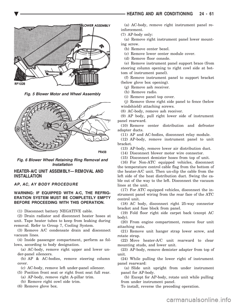
Fig. 5 Blower Motor and Wheel Assembly
Fig. 6 Blower Wheel Retaining Ring Removal and Installation
Ä HEATING AND AIR CONDITIONING 24 - 61