1993 CHEVROLET PLYMOUTH ACCLAIM tire size
[x] Cancel search: tire sizePage 1952 of 2438
(16) Connect the battery ground (negative) cable.
Test the operation of the lights and horns. If applica-
ble, reset the clock and radio.
STEERING COLUMN COMPONENT SERVICE
The Acustar tilt and standard steering columns
(Fig.1) have been designed to be serviced as an as-
sembly; less wiring, switches, shrouds, steering
wheel, etc. Also most steering column components
can be serviced without removing the steering col-
umn from the vehicle. For additional information on
electrical components refer to Group 8H Electrical.
GEAR SHIFT LEVER
The gear shift lever (if equipped) is a serviceable
component of the Acustar steering column assembly.
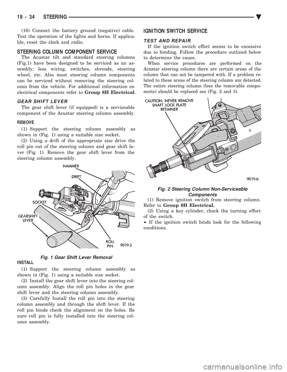
REMOVE (1) Support the steering column assembly as
shown in (Fig. 1) using a suitable size socket. (2) Using a drift of the appropriate size drive the
roll pin out of the steering column and gear shift le-
ver (Fig. 1). Remove the gear shift lever from the
steering column assembly.
INSTALL (1) Support the steering column assembly as
shown in (Fig. 1) using a suitable size socket. (2) Install the gear shift lever into the steering col-
umn assembly. Align the roll pin holes in the gear
shift lever and the steering column assembly. (3) Carefully Install the roll pin into the steering
column assembly and through the shift lever. If the
roll pin binds check the alignment on the holes. Be
sure roll pin is fully installed into the steering col-
umn assembly.
IGNITION SWITCH SERVICE
TEST AND REPAIR
If the ignition switch effort seems to be excessive
due to binding. Follow the procedure outlined below
to determine the cause.
When service procedures are performed on the
Acustar steering column there are certain areas of the
column that can not be tampered with. If a problem re-
lated to these areas of the steering column are detected.
The entire steering column (less the removable compo-
nents) should be replaced see (Fig. 2 and 3).
(1) Remove ignition switch from steering column.
Refer to Group 8H Electrical.
(2) Using a key cylinder, check the turning effort
of the switch.
² If the ignition switch binds look for the following
conditions.
Fig. 1 Gear Shift Lever Removal
Fig. 2 Steering Column Non-Serviceable Components
19 - 34 STEERING Ä
Page 2010 of 2438
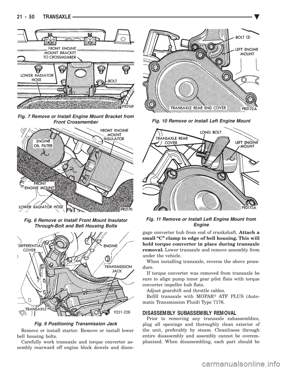
Remove or install starter. Remove or install lower
bell housing bolts. Carefully work transaxle and torque converter as-
sembly rearward off engine block dowels and disen- gage converter hub from end of crankshaft.
Attach a
small ``C'' clamp to edge of bell housing. This will
hold torque converter in place during transaxle
removal. Lower transaxle and remove assembly from
under the vehicle. When installing transaxle, reverse the above proce-
dure. If torque converter was removed from transaxle be
sure to align pump inner gear pilot flats with torque
converter impeller hub flats. Adjust gearshift and throttle cables.
Refill transaxle with MOPAR tATF PLUS (Auto-
matic Transmission Fluid) Type 7176.
DISASSEMBLY SUBASSEMBLY REMOVAL
Prior to removing any transaxle subassemblies,
plug all openings and thoroughly clean exterior of
the unit, preferably by steam. Cleanliness through
entire disassembly and assembly cannot be overem-
phasized. When disassembling, each part should be
Fig. 7 Remove or Install Engine Mount Bracket from Front Crossmember
Fig. 8 Remove or Install Front Mount InsulatorThrough-Bolt and Bell Housing Bolts
Fig. 9 Positioning Transmission Jack
Fig. 10 Remove or Install Left Engine Mount
Fig. 11 Remove or Install Left Engine Mount from Engine
21 - 50 TRANSAXLE Ä
Page 2063 of 2438
SPEED SENSOR-OUTPUT
CAUTION: When disconnecting speed sensor con-
nector, be sure that the weather seal does not fall
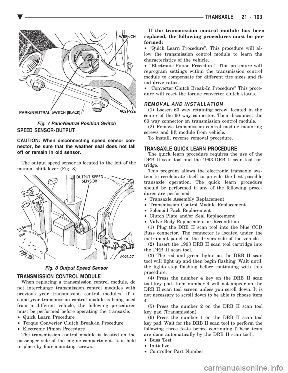
off or remain in old sensor. The output speed sensor is located to the left of the
manual shift lever (Fig. 8).
TRANSMISSION CONTROL MODULE
When replacing a transmission control module, do
not interchange transmission control modules with
previous year transmission control modules. If a
same year transmission control module is being used
from a different vehicle, the following procedures
must be performed before operating the transaxle:
² Quick Learn Procedure
² Torque Converter Clutch Break-in Procedure
² Electronic Pinion Procedure
The transmission control module is located on the
passenger side of the engine compartment. It is held
in place by four mounting screws. If the transmission control module has been
replaced, the following procedures must be per-
formed:
² ``Quick Learn Procedure''. This procedure will al-
low the transmission control module to learn the
characteristics of the vehicle.
² ``Electronic Pinion Procedure''. This procedure will
reprogram settings within the transmission control
module to compensate for different tire sizes and fi-
nal drive ratios.
² ``Converter Clutch Break-In Procedure'' This proce-
dure will reset the torque converter clutch status.
REMOVAL AND INSTALLATION
(1) Loosen 60 way retaining screw, located in the
center of the 60 way connector. Then disconnect the
60 way connector on transmission control module. (2) Remove transmission control module mounting
screws and lift module from vehicle. To install, reverse removal procedure.
TRANSAXLE QUICK LEARN PROCEDURE
The quick learn procedure requires the use of the
DRB II scan tool and the 1993 DRB II scan tool car-
tridge. This program allows the electronic transaxle sys-
tem to recelebrate itself to provide the best possible
transaxle operation. The quick learn procedure
should be performed if any of the following proce-
dures are performed:
² Transaxle Assembly Replacement
² Transmission Control Module Replacement
² Solenoid Pack Replacement
² Clutch Plate and/or Seal Replacement
² Valve Body Replacement or Recondition
(1) Plug the DRB II scan tool into the blue CCD
Buss connector. The connector is located under the
instrument panel on the drivers side of the vehicle. (2) Insert the 1993 DRB II scan tool cartridge into
the DRB II scan tool. (3) The red and green lights on the DRB II scan
tool will light up and then begin flashing. Wait until
the lights stop flashing before continuing with this
procedure. (4) Press the number 4 key on the DRB II scan
tool key pad. Item number 4 will not appear on the
DRB II scan tool screen unless you scroll down. It is
not necessary to scroll down to be able to choose item
4. (5) Press the number 2 on the DRB II scan tool
key pad (Transmission). (6) Press the number 1 on the DRB II scan tool
key pad. Wait for the DRB II scan tool to perform the
following three tests before continuing (These tests
are done automatically by the DRB II scan tool).
² Buss Test
² Initialize
² Controller Part Number
Fig. 7 Park/Neutral Position Switch
Fig. 8 Output Speed Sensor
Ä TRANSAXLE 21 - 103
Page 2064 of 2438
(7) Press the number 5 on the DRB II scan tool
key pad (Adjustments). (8) Press the number 3 on the DRB II scan tool
key pad (Quick Learn). Then follow the instructions
on the DRB II scan tool screen.
PINION FACTOR PROCEDURE
The vehicle speed readings for the speedometer are
taken from the output speed sensor. Because of dif-
ferent tire sizes and final drive ratios, the transmis-
sion control module must be calibrated to reflect the
different combinations of equipment. A procedure has
been developed called Pinion Factor. It allows the
technician to set the transmission control module ini-
tial setting so that the speedometer readings will be
correct. Failure to perform this procedure will cause a ``No
Speedometer Operation'' condition. This procedure must be performed if the transmis-
sion control module has been replaced. To properly read or reset the Pinion Factor, it is
necessary to use a DRB II scan tool. Perform the fol-
lowing steps with the DRB II scan tool to read or re-
set the Pinion Factor: (1) Plug the DRB II scan tool into the blue CCD
Bus connector. The connector is located under the in-
strument panel on the drivers side of the vehicle. (2) Insert the 1993 DRB II scan tool cartridge into
the DRB II scan tool. (3) The red and green lights on the DRB II scan
tool will light up and then begin flashing. Wait until
the lights stop flashing before continuing with this
procedure. (4) Press the number 4 key (Select System) on the
DRB II scan tool key pad. Item number 4 will not ap-
pear on the DRB II scan tool screen unless you scroll
down. It is not necessary to scroll down to be able to
choose item 4. (5) Press the number 2 on the DRB II scan tool
key pad (Transmission). (6) Press the number 1 on the DRB II scan tool
key pad. Wait for the DRB II scan tool to perform the
following three tests before continuing (These tests
are done automatically by the DRB II scan tool).
² Bus Test
² Initialize
² Transmission Control Module Part Number
(7) Press the number 5 on the DRB II scan tool
key pad (Adjustments). (8) Press the number 2 on the DRB II scan tool
key pad (Pinion Factor). Then follow the instructions
on the DRB II scan tool screen.
TORQUE CONVERTER CLUTCH BREAK-IN
PROCEDURE
A torque converter clutch break-in program is be-
ing used on all models with a 41TE. This program
will properly condition the torque converter clutch. This will eliminate shudder during partial torque
converter clutch operation on a new torque converter.
If the torque converter is replaced, the new clutch
within the torque converter will require break-in.
The current break-in status stored in the transmis-
sion control module will have to be reset to the start
of break-in with the DRB II scan tool. If a new transmission control module is put on the
vehicle, the status will be at the start of break-in.
This status is acceptable regardless of the mileage on
the torque converter. No modification of the break-in
status is required. To properly service these vehicles, it is necessary to
use a DRB II scan tool to read or reset the break-in
status. Perform the following steps with the DRB II
scan tool to reset the break-in status: (1) Plug the DRB II scan tool into the blue CCD
Bus connector. The connector is located under the in-
strument panel on the drivers side of the vehicle. (2) Insert the 1993 DRB II scan tool cartridge into
the DRB II scan tool. (3) The red and green lights on the DRB II scan
tool will light up and then begin flashing. Wait until
the lights stop flashing before continuing with this
procedure. (4) Press the number 4 key (Select System) on the
DRB II scan tool key pad. Item number 4 will not ap-
pear on the DRB II scan tool screen unless you scroll
down. It is not necessary to scroll down to be able to
choose item 4. (5) Press the number 2 on the DRB II scan tool
key pad (Transmission). (6) Press the number 1 on the DRB II scan tool
key pad. Wait for the DRB II scan tool to perform the
following three tests before continuing (These tests
are done automatically by the DRB II scan tool).
² Bus Test
² Initialize
² Transmission Control Module Part Number
(7) Press the number 5 on the DRB II scan tool
key pad (Adjustments). (8) Press the number 1 on the DRB II scan tool
key pad (Reset LU Clutch). The DRB II scan tool will
display one of three screens. (a) LU Clutch Break-in Status: Start
(b) LU Clutch Break-in Status: In-progress
Press ENTER to Reset Break-in status (c) LU Clutch Break-in Status: CompletePress
ENTER to Reset Break-in status
If screen (a) appears, the transmission control mod-
ule is at the beginning of its break-in program. No
further action is required. If screen (b) appears, the transmission control mod-
ule is in the middle of a its break-in program. Press
the enter key on the DRB II scan tool key pad to re-
turn the status to the start of break-in.
21 - 104 TRANSAXLE Ä
Page 2092 of 2438
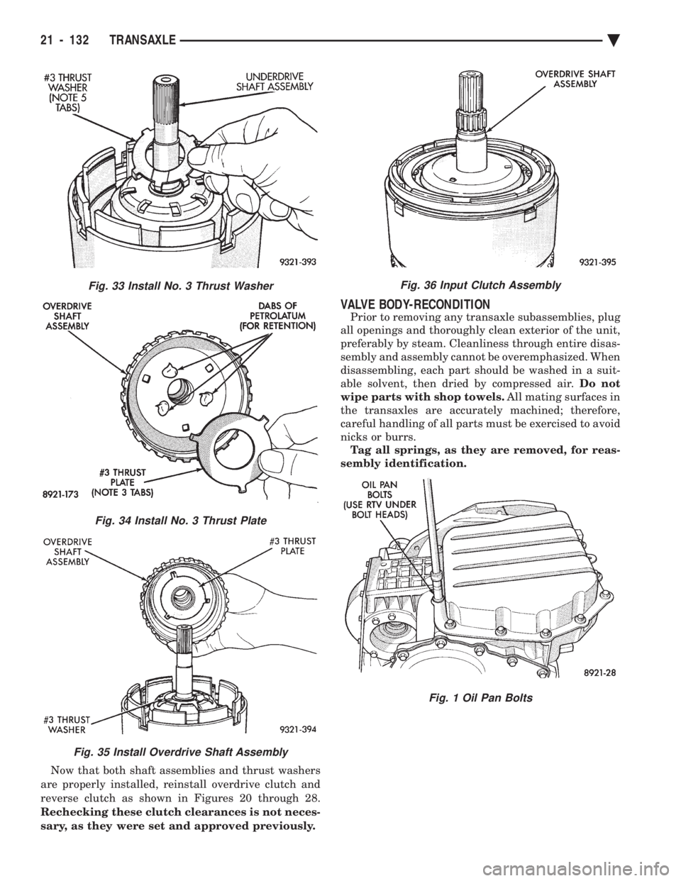
Now that both shaft assemblies and thrust washers
are properly installed, reinstall overdrive clutch and
reverse clutch as shown in Figures 20 through 28.
Rechecking these clutch clearances is not neces-
sary, as they were set and approved previously.
VALVE BODY-RECONDITION
Prior to removing any transaxle subassemblies, plug
all openings and thoroughly clean exterior of the unit,
preferably by steam. Cleanliness through entire disas-
sembly and assembly cannot be overemphasized. When
disassembling, each part should be washed in a suit-
able solvent, then dried by compressed air. Do not
wipe parts with shop towels. All mating surfaces in
the transaxles are accurately machined; therefore,
careful handling of all parts must be exercised to avoid
nicks or burrs. Tag all springs, as they are removed, for reas-
sembly identification.
Fig. 33 Install No. 3 Thrust Washer
Fig. 34 Install No. 3 Thrust Plate
Fig. 35 Install Overdrive Shaft Assembly
Fig. 36 Input Clutch Assembly
Fig. 1 Oil Pan Bolts
21 - 132 TRANSAXLE Ä
Page 2149 of 2438
WHEELSÐTIRES
CONTENTS
page page
SPECIFICATIONS ........................ 8
TIRE SERVICE PROCEDURES .............. 1 WHEELS SERVICE PROCEDURES
........... 6
TIRE SERVICE PROCEDURES INDEX
page page
Cleaning of Tires .......................... 1
General Information ........................ 1
Pressure Gauges ......................... 2
Radial-Ply Tires ........................... 1
Repairing Leaks .......................... 3
Rotation ................................ 3 Spare TireÐCompact
...................... 1
Tire Inflation Pressures ..................... 2
Tire Noise or Vibration ..................... 3
Tire Wear Patterns ........................ 3
Tread Wear Indicators ...................... 3
GENERAL INFORMATION
Throughout this group, references may be made to a
particular vehicle by letter or number designation. A
chart showing the breakdown of these designations is
included in the Introduction Section. Tires are designed for the vehicle and provide the
best overall performance for normal operation. The
ride and handling characteristics match the vehicle's
requirements. With proper care they will give excellent
reliability traction, skid resistance and tread life. They
have load carrying capacity, when properly inflated, to
operate at loads up to the specified Maximum Vehicle
Capacity. Driving habits have more effect on tire life than any
other factor. Careful drivers will obtain, in most cases,
much greater mileage than severe or careless drivers. A
few of the driving habits which will shorten the life of
any tire are:
² Rapid acceleration and deceleration
² Severe application of brakes
² High-speed driving
² Taking turns at excessive speeds
² Striking curbs and other obstacles
Radial ply tires can be more susceptible to irregular
tread wear. It is very important to follow the tire
rotation interval shown in the section on Tire
Rotation to achieve a greater tread life potential.
RADIAL-PLY TIRES
Radial-ply tires improve handling, tread life, and
ride quality and decrease rolling resistance. Radial-ply tires must always be used in sets of four
and under no circumstances should they be used on
the front only. However, they may be mixed with temporary spare tires when necessary,
but reduced speeds are recommended. Radial-ply tires have the same load carrying capac-
ity as other types of tires of the same size. They also
use the same recommended inflation pressures.
SPARE TIREÐCOMPACT
The compact spare tire is designed for emergency
use only. The original tire should be repaired and re-
installed at the first opportunity. Refer to Owner's
Manual for complete details.
TIRE CHAINS
Tire snow chains may be used on certainmodels.
Refer to Owner's Manual for more information.
CLEANING OF TIRES
Remove protective coating on tires before delivery
of vehicle, otherwise it could cause deterioration of
tires. Remove protective coating by applying warm wa-
ter, letting it soak one minute, and then scrubbing
the coating away with a soft bristle brush. Steam cleaning may also be used for cleaning.
DO NOT use gasoline or wire brush for cleaning.
DO NOT use mineral oil or an oil-based solvent.
Ä WHEELSÐTIRES 22 - 1
Page 2150 of 2438
PRESSURE GAUGES
High quality dial type air pressure gauges are rec-
ommended. After checking pressure with the gauge,
replace valve caps and tighten finger tight.
TIRE INFLATION PRESSURES
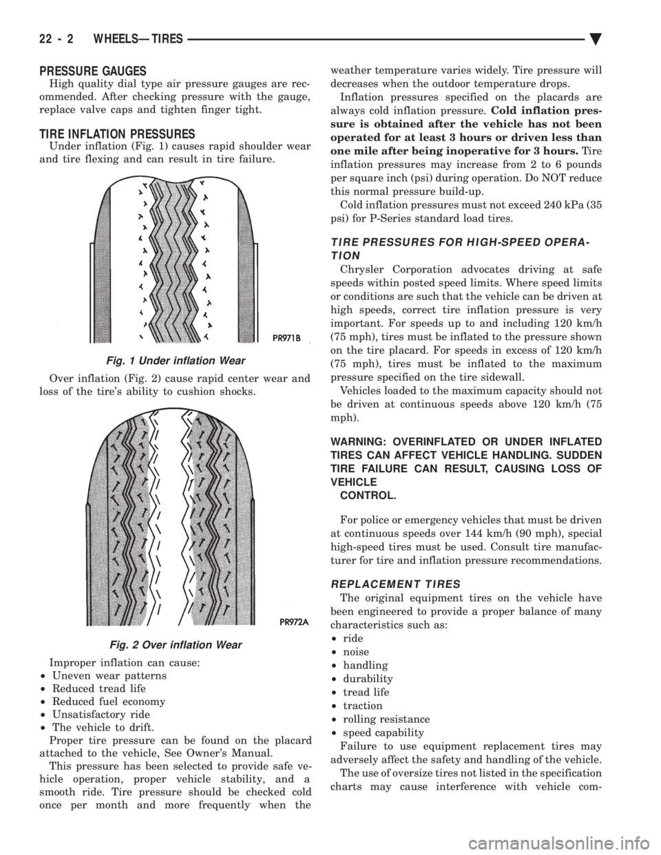
Under inflation (Fig. 1) causes rapid shoulder wear
and tire flexing and can result in tire failure.
Over inflation (Fig. 2) cause rapid center wear and
loss of the tire's ability to cushion shocks.
Improper inflation can cause:
² Uneven wear patterns
² Reduced tread life
² Reduced fuel economy
² Unsatisfactory ride
² The vehicle to drift.
Proper tire pressure can be found on the placard
attached to the vehicle, See Owner's Manual. This pressure has been selected to provide safe ve-
hicle operation, proper vehicle stability, and a
smooth ride. Tire pressure should be checked cold
once per month and more frequently when the weather temperature varies widely. Tire pressure will
decreases when the outdoor temperature drops.
Inflation pressures specified on the placards are
always cold inflation pressure. Cold inflation pres-
sure is obtained after the vehicle has not been
operated for at least 3 hours or driven less than
one mile after being inoperative for 3 hours. Tire
inflation pressures may increase from 2 to 6 pounds
per square inch (psi) during operation. Do NOT reduce
this normal pressure build-up. Cold inflation pressures must not exceed 240 kPa (35
psi) for P-Series standard load tires.
TIRE PRESSURES FOR HIGH-SPEED OPERA- TION
Chrysler Corporation advocates driving at safe
speeds within posted speed limits. Where speed limits
or conditions are such that the vehicle can be driven at
high speeds, correct tire inflation pressure is very
important. For speeds up to and including 120 km/h
(75 mph), tires must be inflated to the pressure shown
on the tire placard. For speeds in excess of 120 km/h
(75 mph), tires must be inflated to the maximum
pressure specified on the tire sidewall. Vehicles loaded to the maximum capacity should not
be driven at continuous speeds above 120 km/h (75
mph).
WARNING: OVERINFLATED OR UNDER INFLATED
TIRES CAN AFFECT VEHICLE HANDLING. SUDDEN
TIRE FAILURE CAN RESULT, CAUSING LOSS OF
VEHICLE CONTROL.
For police or emergency vehicles that must be driven
at continuous speeds over 144 km/h (90 mph), special
high-speed tires must be used. Consult tire manufac-
turer for tire and inflation pressure recommendations.
REPLACEMENT TIRES
The original equipment tires on the vehicle have
been engineered to provide a proper balance of many
characteristics such as:
² ride
² noise
² handling
² durability
² tread life
² traction
² rolling resistance
² speed capability
Failure to use equipment replacement tires may
adversely affect the safety and handling of the vehicle. The use of oversize tires not listed in the specification
charts may cause interference with vehicle com-
Fig. 1 Under inflation Wear
Fig. 2 Over inflation Wear
22 - 2 WHEELSÐTIRES Ä