1993 CHEVROLET PLYMOUTH ACCLAIM service reset
[x] Cancel search: service resetPage 529 of 2438
CONDITION: US/METRIC MODES WILL NOT TOGGLE OR TRIP ODOMETER WILL NOTRESET
PROCEDURE
(1) Perform cluster self-diagnostics to determine if
push buttons are operational. (2) Refer to the Body Chassis Diagnostic Manual
to diagnose CCD Bus. The US/Metric toggle and trip
odometer reset are activated over the CCD Bus.
ODOMETER ADJUSTMENT
The odometer memory is no longer retained in the
cluster. This information is stored in the body con-
troller. Therefore, there is no adjustment procedure.
If the cluster is replaced odometer value will not
change. If the body controller is replaced the mileage
may be transferred using the DRB II. Refer to the
Body Chassis Diagnostic Manual for the procedure.
SWITCH AND PANEL COMPONENT SERVICE
MESSAGE CENTER REPLACEMENT
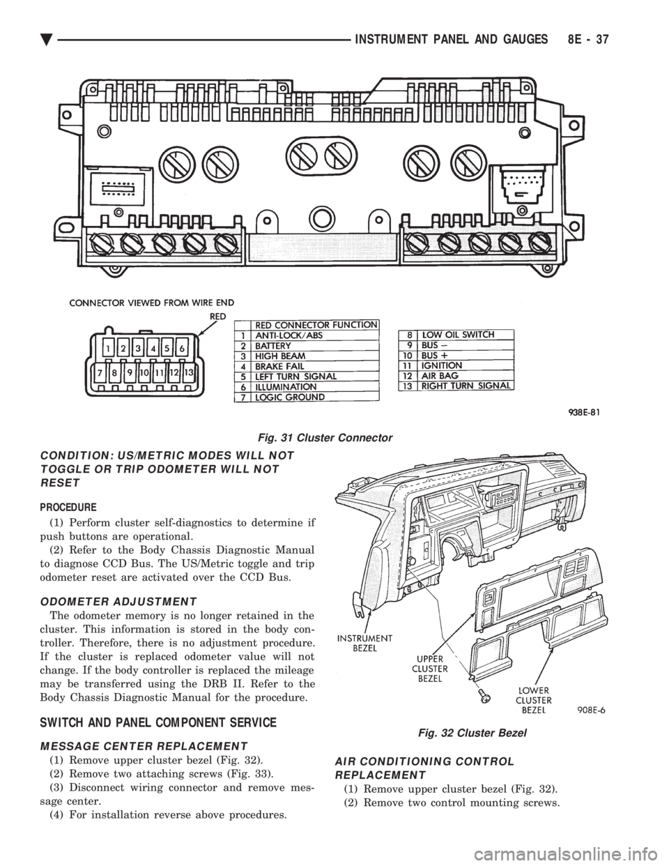
(1) Remove upper cluster bezel (Fig. 32).
(2) Remove two attaching screws (Fig. 33).
(3) Disconnect wiring connector and remove mes-
sage center. (4) For installation reverse above procedures.AIR CONDITIONING CONTROLREPLACEMENT
(1) Remove upper cluster bezel (Fig. 32).
(2) Remove two control mounting screws.
Fig. 31 Cluster Connector
Fig. 32 Cluster Bezel
Ä INSTRUMENT PANEL AND GAUGES 8E - 37
Page 1582 of 2438
POWER STEERING/ACCESSORY DRIVE BELT TENSIONER BRACKET
REMOVAL
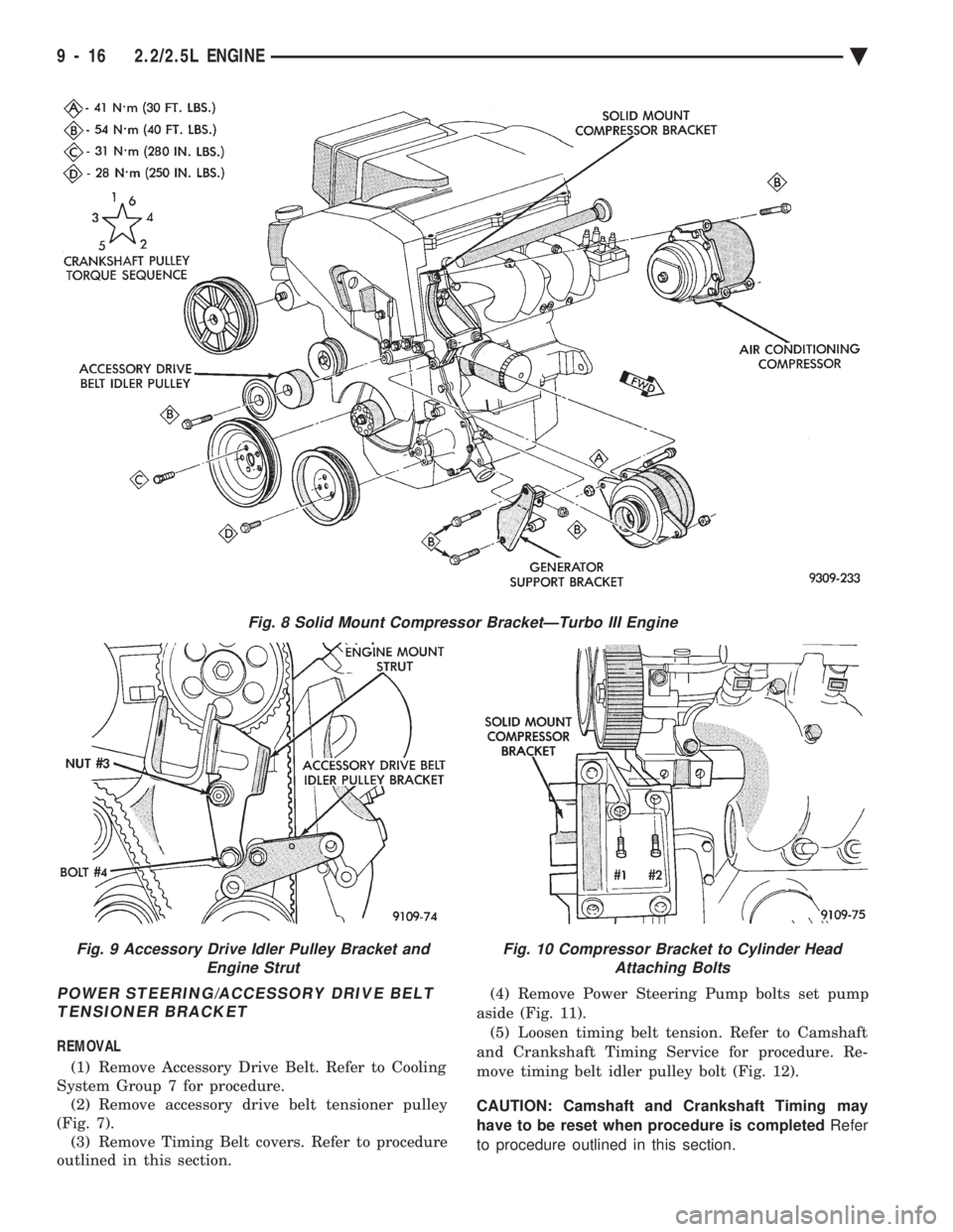
(1) Remove Accessory Drive Belt. Refer to Cooling
System Group 7 for procedure. (2) Remove accessory drive belt tensioner pulley
(Fig. 7). (3) Remove Timing Belt covers. Refer to procedure
outlined in this section. (4) Remove Power Steering Pump bolts set pump
aside (Fig. 11). (5) Loosen timing belt tension. Refer to Camshaft
and Crankshaft Timing Service for procedure. Re-
move timing belt idler pulley bolt (Fig. 12).
CAUTION: Camshaft and Crankshaft Timing may
have to be reset when procedure is completed Refer
to procedure outlined in this section.
Fig. 8 Solid Mount Compressor BracketÐTurbo III Engine
Fig. 9 Accessory Drive Idler Pulley Bracket and Engine StrutFig. 10 Compressor Bracket to Cylinder HeadAttaching Bolts
9 - 16 2.2/2.5L ENGINE Ä
Page 1952 of 2438
(16) Connect the battery ground (negative) cable.
Test the operation of the lights and horns. If applica-
ble, reset the clock and radio.
STEERING COLUMN COMPONENT SERVICE
The Acustar tilt and standard steering columns
(Fig.1) have been designed to be serviced as an as-
sembly; less wiring, switches, shrouds, steering
wheel, etc. Also most steering column components
can be serviced without removing the steering col-
umn from the vehicle. For additional information on
electrical components refer to Group 8H Electrical.
GEAR SHIFT LEVER
The gear shift lever (if equipped) is a serviceable
component of the Acustar steering column assembly.
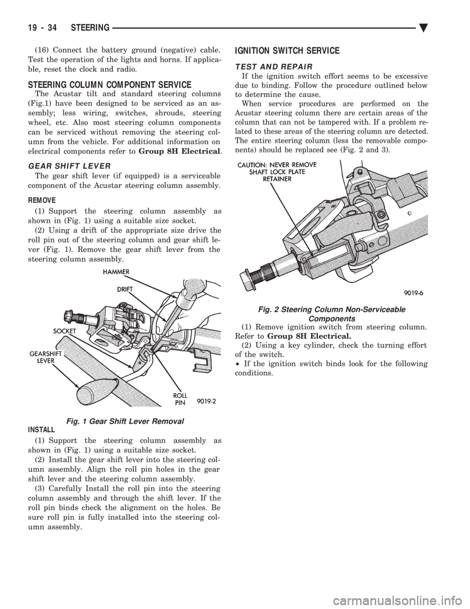
REMOVE (1) Support the steering column assembly as
shown in (Fig. 1) using a suitable size socket. (2) Using a drift of the appropriate size drive the
roll pin out of the steering column and gear shift le-
ver (Fig. 1). Remove the gear shift lever from the
steering column assembly.
INSTALL (1) Support the steering column assembly as
shown in (Fig. 1) using a suitable size socket. (2) Install the gear shift lever into the steering col-
umn assembly. Align the roll pin holes in the gear
shift lever and the steering column assembly. (3) Carefully Install the roll pin into the steering
column assembly and through the shift lever. If the
roll pin binds check the alignment on the holes. Be
sure roll pin is fully installed into the steering col-
umn assembly.
IGNITION SWITCH SERVICE
TEST AND REPAIR
If the ignition switch effort seems to be excessive
due to binding. Follow the procedure outlined below
to determine the cause.
When service procedures are performed on the
Acustar steering column there are certain areas of the
column that can not be tampered with. If a problem re-
lated to these areas of the steering column are detected.
The entire steering column (less the removable compo-
nents) should be replaced see (Fig. 2 and 3).
(1) Remove ignition switch from steering column.
Refer to Group 8H Electrical.
(2) Using a key cylinder, check the turning effort
of the switch.
² If the ignition switch binds look for the following
conditions.
Fig. 1 Gear Shift Lever Removal
Fig. 2 Steering Column Non-Serviceable Components
19 - 34 STEERING Ä
Page 1964 of 2438
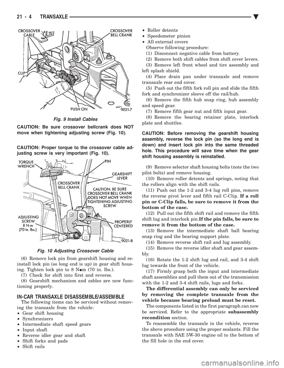
CAUTION: Be sure crossover bellcrank does NOT
move when tightening adjusting screw (Fig. 10).
CAUTION: Proper torque to the crossover cable ad-
justing screw is very important (Fig. 10).
(6) Remove lock pin from gearshift housing and re-
install lock pin (so long end is up) in gear shift hous-
ing. Tighten lock pin to 8 N Im (70 in. lbs.).
(7) Check for shift into first and reverse.
(8) Gearshift mechanism and cables are now func-
tioning properly.
IN-CAR TRANSAXLE DISASSEMBLE/ASSEMBLE
The following items can be serviced without remov-
ing the transaxle from the vehicle:
² Gear shift housing
² Synchronizers
² Intermediate shaft speed gears
² Input shaft
² Reverse idler gear and shaft
² Shift forks and pads
² Shift rails ²
Roller detents
² Speedometer pinion
² All external covers
Observe following procedure:
(1) Disconnect negative cable from battery.
(2) Remove both shift cables from shift cover levers.
(3) Remove left front wheel and tire assembly and
left splash shield. (4) Place drain pan under transaxle and remove
transaxle rear end cover. (5) Push out the fifth fork roll pin and slide the fifth
fork and synchronizer sleeve off the rail/hub. (6) Remove the fifth hub snap ring, hub assembly
and speed gear. (7) Remove fifth gear nut and fifth input gear.
(8) Remove the bearing retainer plate, interlock
plate and shuttles.
CAUTION: Before removing the gearshift housing
assembly, reverse the lock pin (so the long end is
down) and insert lock pin into the same threaded
hole. This procedure will save time when the gear
shift housing assembly is reinstalled. (9) Remove selector shaft housing bolts (note the two
pilot bolts) and remove housing. (10) Remove roller detents and springs, noting that
the rollers align with the shift rails. (11) Push out the 1-2 and 3-4 lug roll pins, remove
the reverse pivot lever and fifth rail C-Clip. If a roll
pin or C-Clip falls, be sure to remove it from the
bottom of the case. (12) Pull out the fifth shift rail and remove the fifth
shift lug and interlock pin. If the pin falls, be sure to
remove it from the bottom of the case. (13) Remove the intermediate shaft ball bearing
snap ring and the bearing support plate. (14) Remove reverse shift rail and lug assembly.
(15) Remove the reverse idler shaft and gear assem-
bly. (16) Rotate the 1-2 shift lug and rail, and 3-4 shift
lug towards the front of the vehicle. (17) Firmly grasp both the input and intermediate
shaft assemblies and pull them out of the transmission
with the 1-2 and 3-4 shift rails, lugs and forks. The differential assembly can only be serviced
by removing the complete transaxle from the
vehicle because bearing preload must be reset. The components listed in the first paragraph can now
be serviced. Refer to the appropriate subassembly
recondition section.
To reassemble the transaxle in the vehicle, reverse
the above procedure using the proper sealants. Fill the
transaxle with SAE 5W-30 engine oil to the bottom of
the fill hole in the end cover.
Fig. 9 Install Cables
Fig. 10 Adjusting Crossover Cable
21 - 4 TRANSAXLE Ä
Page 2064 of 2438
(7) Press the number 5 on the DRB II scan tool
key pad (Adjustments). (8) Press the number 3 on the DRB II scan tool
key pad (Quick Learn). Then follow the instructions
on the DRB II scan tool screen.
PINION FACTOR PROCEDURE
The vehicle speed readings for the speedometer are
taken from the output speed sensor. Because of dif-
ferent tire sizes and final drive ratios, the transmis-
sion control module must be calibrated to reflect the
different combinations of equipment. A procedure has
been developed called Pinion Factor. It allows the
technician to set the transmission control module ini-
tial setting so that the speedometer readings will be
correct. Failure to perform this procedure will cause a ``No
Speedometer Operation'' condition. This procedure must be performed if the transmis-
sion control module has been replaced. To properly read or reset the Pinion Factor, it is
necessary to use a DRB II scan tool. Perform the fol-
lowing steps with the DRB II scan tool to read or re-
set the Pinion Factor: (1) Plug the DRB II scan tool into the blue CCD
Bus connector. The connector is located under the in-
strument panel on the drivers side of the vehicle. (2) Insert the 1993 DRB II scan tool cartridge into
the DRB II scan tool. (3) The red and green lights on the DRB II scan
tool will light up and then begin flashing. Wait until
the lights stop flashing before continuing with this
procedure. (4) Press the number 4 key (Select System) on the
DRB II scan tool key pad. Item number 4 will not ap-
pear on the DRB II scan tool screen unless you scroll
down. It is not necessary to scroll down to be able to
choose item 4. (5) Press the number 2 on the DRB II scan tool
key pad (Transmission). (6) Press the number 1 on the DRB II scan tool
key pad. Wait for the DRB II scan tool to perform the
following three tests before continuing (These tests
are done automatically by the DRB II scan tool).
² Bus Test
² Initialize
² Transmission Control Module Part Number
(7) Press the number 5 on the DRB II scan tool
key pad (Adjustments). (8) Press the number 2 on the DRB II scan tool
key pad (Pinion Factor). Then follow the instructions
on the DRB II scan tool screen.
TORQUE CONVERTER CLUTCH BREAK-IN
PROCEDURE
A torque converter clutch break-in program is be-
ing used on all models with a 41TE. This program
will properly condition the torque converter clutch. This will eliminate shudder during partial torque
converter clutch operation on a new torque converter.
If the torque converter is replaced, the new clutch
within the torque converter will require break-in.
The current break-in status stored in the transmis-
sion control module will have to be reset to the start
of break-in with the DRB II scan tool. If a new transmission control module is put on the
vehicle, the status will be at the start of break-in.
This status is acceptable regardless of the mileage on
the torque converter. No modification of the break-in
status is required. To properly service these vehicles, it is necessary to
use a DRB II scan tool to read or reset the break-in
status. Perform the following steps with the DRB II
scan tool to reset the break-in status: (1) Plug the DRB II scan tool into the blue CCD
Bus connector. The connector is located under the in-
strument panel on the drivers side of the vehicle. (2) Insert the 1993 DRB II scan tool cartridge into
the DRB II scan tool. (3) The red and green lights on the DRB II scan
tool will light up and then begin flashing. Wait until
the lights stop flashing before continuing with this
procedure. (4) Press the number 4 key (Select System) on the
DRB II scan tool key pad. Item number 4 will not ap-
pear on the DRB II scan tool screen unless you scroll
down. It is not necessary to scroll down to be able to
choose item 4. (5) Press the number 2 on the DRB II scan tool
key pad (Transmission). (6) Press the number 1 on the DRB II scan tool
key pad. Wait for the DRB II scan tool to perform the
following three tests before continuing (These tests
are done automatically by the DRB II scan tool).
² Bus Test
² Initialize
² Transmission Control Module Part Number
(7) Press the number 5 on the DRB II scan tool
key pad (Adjustments). (8) Press the number 1 on the DRB II scan tool
key pad (Reset LU Clutch). The DRB II scan tool will
display one of three screens. (a) LU Clutch Break-in Status: Start
(b) LU Clutch Break-in Status: In-progress
Press ENTER to Reset Break-in status (c) LU Clutch Break-in Status: CompletePress
ENTER to Reset Break-in status
If screen (a) appears, the transmission control mod-
ule is at the beginning of its break-in program. No
further action is required. If screen (b) appears, the transmission control mod-
ule is in the middle of a its break-in program. Press
the enter key on the DRB II scan tool key pad to re-
turn the status to the start of break-in.
21 - 104 TRANSAXLE Ä