1993 CHEVROLET PLYMOUTH ACCLAIM radiator cap
[x] Cancel search: radiator capPage 360 of 2438

RADIATOR PRESSURE CAP
Radiators are equipped with a pressure cap which
releases pressure at some point within a range of
97-124 kPa (14-18 psi) (Fig. 7). The system will operate at higher than atmospheric
pressure which raises the coolant boiling point allow-
ing increased radiator cooling capacity. There is also a vent valve in the center of the cap that
allows a small coolant flow to the CRS tank. If valve is
stuck shut, the radiator hoses will be collapsed
on cool down. Clean the vent valve (Fig. 7) to
ensure proper sealing when boiling point is
reached.
There is also a gasket in the cap to seal to the top of
the filler neck so that vacuum can be maintained for
drawing coolant back into the radiator from the coolant
reserve system tank.
RADIATOR CAP TO FILLER NECK SEAL PRES- SURE RELIEF CHECK
The pressure cap upper gasket (seal) pressure relief
can be checked by removing the overflow hose at the
radiator filler neck nipple (Fig. 7). Attach the Radiator
Pressure Tool to the filler neck nipple and pump air
into the radiator. Pressure cap upper gasket should
relieve at 69-124 kPa (10-18 psi) and hold pressure at
55 kPa (8 psi) minimum.
WARNING: THE WARNING WORDS DO NOT OPEN
HOT ON THE RADIATOR PRESSURE CAP IS A
SAFETY PRECAUTION. WHEN HOT, PRESSURE
BUILDS UP IN COOLING SYSTEM. TO PREVENT
SCALDING OR INJURY, THE RADIATOR CAP
SHOULD NOT BE REMOVED WHILE THE SYSTEM IS
HOT AND/OR UNDER PRESSURE.
There is no need to remove the radiator cap at any
time except for the following purposes:
(1) Check and adjust antifreeze freeze point.
(2) Refill system with new antifreeze.
(3) Conducting service procedures.
(4) Checking for vacuum leaks.
WARNING: IF VEHICLE HAS BEEN RUN RECENTLY,
WAIT 15 MINUTES BEFORE REMOVING CAP. THEN PLACE A SHOP TOWEL OVER THE CAP AND WITH-
OUT PUSHING DOWN ROTATE IT COUNTER-
CLOCKWISE TO THE FIRST STOP. ALLOW FLUIDS
TO ESCAPE THROUGH THE OVERFLOW TUBE AND
WHEN THE SYSTEM STOPS PUSHING COOLANT
AND STEAM INTO THE CRS TANK AND PRESSURE
DROPS PUSH DOWN AND REMOVE THE CAP COM-
PLETELY. SQUEEZING THE RADIATOR INLET HOSE
WITH A SHOP TOWEL (TO CHECK PRESSURE) BE-
FORE AND AFTER TURNING TO THE FIRST STOP IS
RECOMMENDED.
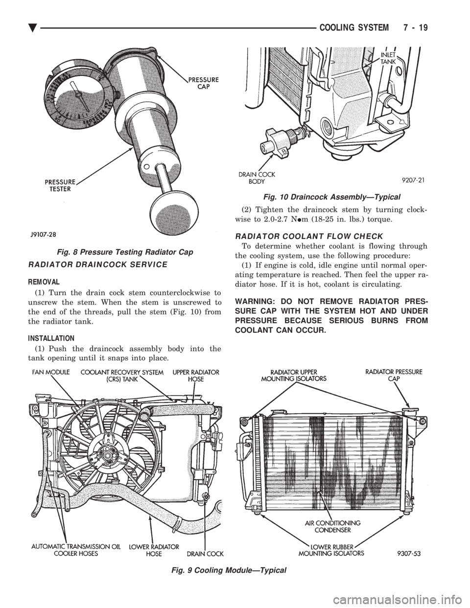
PRESSURE TESTING RADIATOR CAPS
Dip the pressure cap in water, clean any deposits off
the vent valve or its seat and apply cap to end of
Radiator Pressure Tool. Working the plunger, bring the
pressure to 104 kPa (15 psi) on the gauge. If the
pressure cap fails to hold pressure of at least 97 kPa
(14 psi) replace cap. See CAUTION
If the pressure cap tests properly while positioned on
Radiator Pressure Tool, but will not hold pressure or
vacuum when positioned on the radiator. Inspect the
radiator filler neck and cap top gasket for irregularities
that may prevent the cap from sealing properly.
CAUTION: Radiator Pressure Tool is very sensitive to
small air leaks which will not cause cooling system
problems. A pressure cap that does not have a
history of coolant loss should not be replaced just
because it leaks slowly when tested with this tool.
Add water to the tool. Turn tool upside down and
recheck pressure cap to confirm that cap is bad.
INSPECTION
Hold the cap in hand, right side up(Fig. 7). The
vent valve at the bottom of the cap should open. If the
rubber gasket has swollen and prevents the valve from
opening, replace the cap. Hold the cleaned cap in hand upside down.If any
light can be seen between vent valve and rubber
gasket, replace cap. Do not use a replacement cap
that has a spring to hold the vent shut. Replacement cap must be of the type designed for
coolant reserve systems. This design assures coolant
return to radiator.
RADIATORS
The radiators are crossflow types (horizontal tubes)
with design features that provide greater strength as
well as sufficient heat transfer capabilities to keep the
engine satisfactorily cooled.
CAUTION: Plastic tanks, while stronger then brass
are subject to damage by impact, such as wrenches.
Fig. 7 Radiator Pressure Cap Filler Neck
7 - 18 COOLING SYSTEM Ä
Page 361 of 2438

RADIATOR DRAINCOCK SERVICE
REMOVAL (1) Turn the drain cock stem counterclockwise to
unscrew the stem. When the stem is unscrewed to
the end of the threads, pull the stem (Fig. 10) from
the radiator tank.
INSTALLATION (1) Push the draincock assembly body into the
tank opening until it snaps into place. (2) Tighten the draincock stem by turning clock-
wise to 2.0-2.7 N Im (18-25 in. lbs.) torque.
RADIATOR COOLANT FLOW CHECK
To determine whether coolant is flowing through
the cooling system, use the following procedure: (1) If engine is cold, idle engine until normal oper-
ating temperature is reached. Then feel the upper ra-
diator hose. If it is hot, coolant is circulating.
WARNING: DO NOT REMOVE RADIATOR PRES-
SURE CAP WITH THE SYSTEM HOT AND UNDER
PRESSURE BECAUSE SERIOUS BURNS FROM
COOLANT CAN OCCUR.
Fig. 9 Cooling ModuleÐTypical
Fig. 8 Pressure Testing Radiator Cap
Fig. 10 Draincock AssemblyÐTypical
Ä COOLING SYSTEM 7 - 19
Page 362 of 2438

(2) Remove radiator pressure cap when engine is
cold, Idle engine until thermostat opens, you should
observe coolant flow while looking down the filler
neck. Once flow is detected install radiator pressure
cap.
RADIATOR
REMOVAL
(1) Disconnect negative battery cable from battery.
WARNING: DO NOT REMOVE THE CYLINDER
BLOCK PLUG OR THE RADIATOR DRAINCOCK
WITH THE SYSTEM HOT AND UNDER PRESSURE
BECAUSE SERIOUS BURNS FROM COOLANT CAN
OCCUR.
(2) Drain cooling system. Refer to Draining Cool-
ing System of this section. (3) Remove hose clamps and hoses from the radia-
tor (Fig. 11). Remove coolant reserve system tank to
filler neck tube. (4) Remove automatic transmission hoses, if
equipped. (5) Remove fan and fan support assembly by dis-
connecting fan motor electrical connector. Remove
fan shroud retaining clips, located on the top and
bottom of the shroud for AA, AG, AJ and AP vehi-
cles. AC/AY vehicle retainer clips are located on the
top only. Lift shroud up and out of bottom shroud at-
tachment clips separating shroud from radiator. Fan
damage should always be avoided. (6) Remove upper radiator mounting screws. Dis-
connect the engine block heater wire if equipped. (7) Remove the air conditioning condenser attaching
screws located at the top front of the radiator,if
equipped. Radiator can now be lifted free from engine compart-
ment. Care should be taken not to damage radia-
tor cooling fins or water tubes during removal.
INSTALLATION
(1) Slide radiator down into position behind radiator
support (yoke). (2) Attach air conditioning condenser to radiator, if
equipped, with a force of approximately 10 lbs. to seat
the radiator assembly lower rubber isolators in the
mount holes provided. (3) Tighten radiator mounting screws to 11.9N Im
(105 in. lbs.). (4) Connect automatic transmission hoses, if
equipped. Tighten hose clamps to 4 N Im (35 in. lbs.).
(5) Slide fan shroud, fan and motor down into clips
on lower radiator flange. Replace shroud retaining
clips. (6) Install upper and lower radiator hoses (including
coolant reserve hose). (7) Connect fan motor electrical connection and con-
nect negative battery cable. (8) Fill cooling system with coolant. Refer to Refill-
ing Cooling Systems. in this group.
(9) Operate engine until it reaches normal operating
temperature. Check cooling system and automatic
transmission for correct fluid levels.
Fig. 11 Cooling ModulesÐAll Models
7 - 20 COOLING SYSTEM Ä
Page 684 of 2438

FRONT IMPACT SENSORS
The driver air bag system is a safety device de-
signed to reduce the risk of fatality or serious injury,
caused by a frontal impact of the vehicle. The impact sensors provide verification of the di-
rection and severity of the impact. Three impact sen-
sors are used. One is called a safing sensor. It is
located inside the diagnostic module which is
mounted on the floor pan, just forward of the center
console. The other two sensors are mounted on the
upper crossmember of the radiator closure panel on
the left and right side of the vehicle under the hood. The impact sensors are threshold sensitive switches
that complete an electrical circuit when an impact
provides a sufficient G force to close the switch. The
sensors are calibrated for the specific vehicle and re-
act to the severity and direction of the impact.
CLOCKSPRING
The clockspring is mounted on the steering column
behind the steering wheel, and is used to maintain a
continuous electrical circuit between the wiring har-
ness and the driver's air bag module. This assembly
consists of a flat ribbon-like electrically conductive
tape which winds and unwinds with the steering
wheel rotation.
DIAGNOSTIC MODULE
The Air Bag System Diagnostic Module (ASDM)
contains the safing sensor and energy reserve capac-
itor. The ASDM monitors the system to determine
the system readiness. The ASDM will store sufficient
energy to deploy the air bag for only two minutes af-
ter the battery is disconnected. If both front impact
sensors are open the air bag could be deployed up to
9.5 minutes after the battery is disconnected. The
ASDM contains on-board diagnostics, and will illumi-
nate the AIR BAG warning lamp in the cluster when
a fault occurs.
STORAGE
The air bag module must be stored in its original
special container until used for service. Additionally,
it must be stored in a clean, dry environment, away
from sources of extreme heat, sparks, and sources of
high electrical energy. Always place or store the
module on a surface with the trim cover facing up to
minimize movement in case of accidental deploy-
ment.
HANDLING LIVE MODULE
At no time should any source of electricity be per-
mitted near the inflator on the back of the module.
When carrying a live module, the trim cover should
be pointed away from the body to minimize injury in
the event of accidental deployment. In addition, if
the module is placed on a bench or other surface, the plastic trim cover should be face up to minimize
movement in case of accidental deployment. When handling a steering column with an air bag
module attached, never place the column on the floor
or other surface with the steering wheel or module
face down.
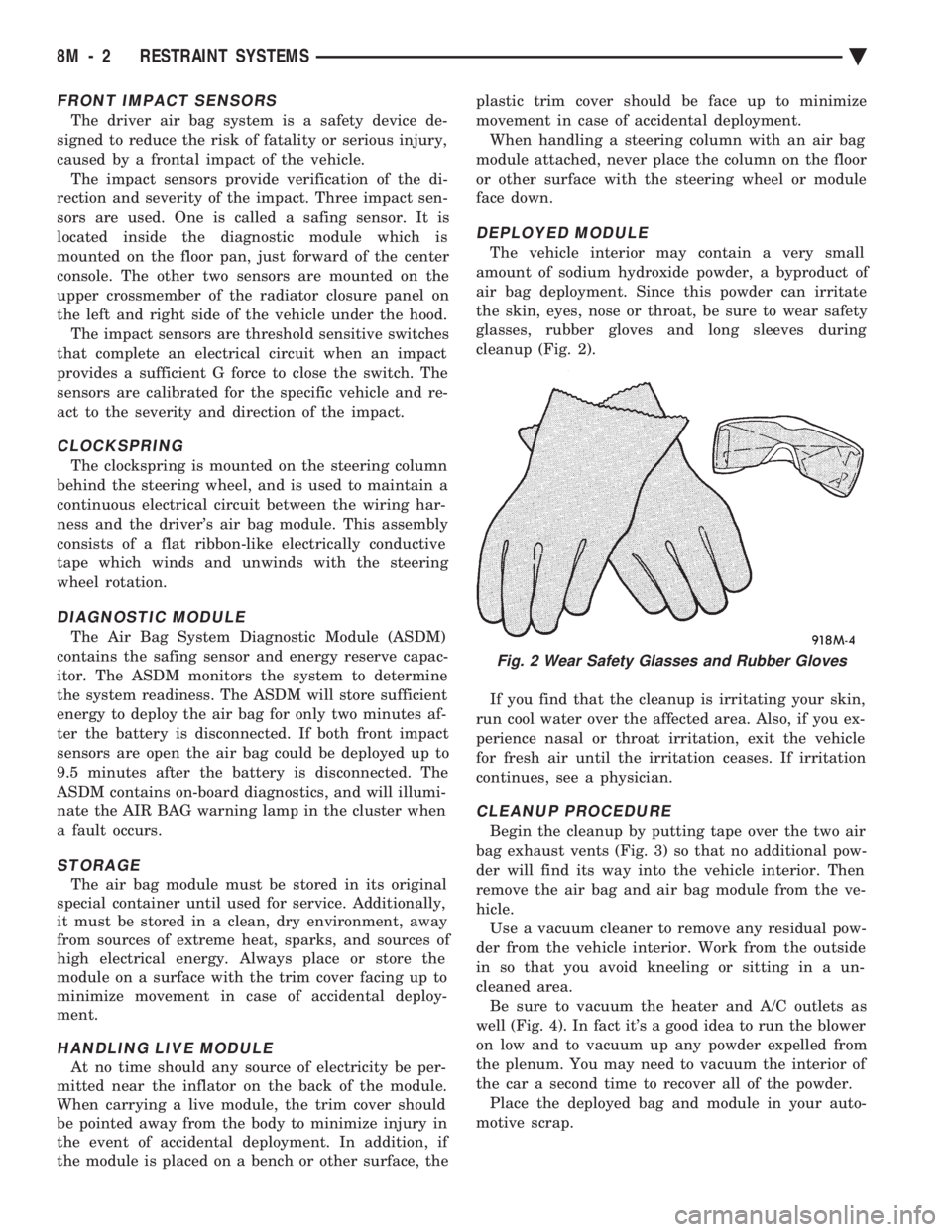
DEPLOYED MODULE
The vehicle interior may contain a very small
amount of sodium hydroxide powder, a byproduct of
air bag deployment. Since this powder can irritate
the skin, eyes, nose or throat, be sure to wear safety
glasses, rubber gloves and long sleeves during
cleanup (Fig. 2).
If you find that the cleanup is irritating your skin,
run cool water over the affected area. Also, if you ex-
perience nasal or throat irritation, exit the vehicle
for fresh air until the irritation ceases. If irritation
continues, see a physician.
CLEANUP PROCEDURE
Begin the cleanup by putting tape over the two air
bag exhaust vents (Fig. 3) so that no additional pow-
der will find its way into the vehicle interior. Then
remove the air bag and air bag module from the ve-
hicle. Use a vacuum cleaner to remove any residual pow-
der from the vehicle interior. Work from the outside
in so that you avoid kneeling or sitting in a un-
cleaned area. Be sure to vacuum the heater and A/C outlets as
well (Fig. 4). In fact it's a good idea to run the blower
on low and to vacuum up any powder expelled from
the plenum. You may need to vacuum the interior of
the car a second time to recover all of the powder. Place the deployed bag and module in your auto-
motive scrap.
Fig. 2 Wear Safety Glasses and Rubber Gloves
8M - 2 RESTRAINT SYSTEMS Ä
Page 685 of 2438

SERVICE OF DEPLOYED AIR BAG MODULE
After an air bag has been deployed, the air bag
module and clockspring must be replaced because
they cannot be reused. Other air bag system compo-
nents are replaced if damaged.
SCHEDULED MAINTENANCE INSPECTION
Vehicles equipped with a Air Bag System must be
inspected every three years or 30,000 miles / 48,000
Km. The following items should be inspected. (1) Inspect components for damage or deteriora-
tion. (a) If the air bag module housing shows signs of
physical damage or abuse, replace the module. (b) Check that both front impact sensors are
properly installed to the upper crossmember of the
radiator closure panel. Repair as required.
(2) Check the air bag warning lamp for proper op-
eration as follows: (a) Turn ignition switch to the ON position, the
air bag warning lamp should light. If not, test the system using the DRB II and Passive Restraint
System Diagnostic Procedures Manual. Repair as
required.
(b) The air bag warning lamp lights, but fails to go
out after ten seconds. Test the system using the DRB
II and Passive Restraint System Diagnostic Proce-
dures Manual. Repair as required. (c) Erasing of fault codes is not required.
AIR BAG SYSTEM CHECK
WARNING: BEFORE BEGINNING ANY AIR BAG SYS-
TEM CHECK PROCEDURES, REMOVE AND ISOLATE
THE BATTERY NEGATIVE (-) CABLE (GROUND)
FROM THE VEHICLE BATTERY. THIS IS THE ONLY
SURE WAY TO DISABLE THE AIR BAG SYSTEM.
FAILURE TO DO THIS COULD RESULT IN ACCIDEN-
TAL AIR BAG DEPLOYMENT AND POSSIBLE PER-
SONAL INJURY.
WHEN AN UNDEPLOYED AIR BAG ASSEMBLY IS
TO BE REMOVED FROM THE STEERING WHEEL,
DISCONNECT BATTERY GROUND CABLE AND
ISOLATE. ALLOW SYSTEM CAPACITOR TO DIS-
CHARGE FOR TWO MINUTES, THEN BEGIN AIR
BAG REMOVAL. (1) Disconnect the battery negative cable and iso-
late. (2) Remove forward console or cover as necessary.
(3) Connect DRB II to ASDM diagnostic 6-way con-
nector, located at right side of module. (4) Turn the ignition key to ON position. Exit vehicle
with DRB II. Use the latest version of the proper
cartridge. (5) After checking that no one is inside the vehicle,
connect the negative battery cable. (6) Using the DRB II, read and record active fault
data. (7) Read and record any stored faults.
(8) Refer to the Passive Restraint Diagnostic Test
Manual if any faults are found in steps 6 and 7. (9) Erase stored faults if there are no active fault
codes. If problems remain, fault codes will not erase. (10) With the ignition key in the ON position, make
sure no one is in the vehicle. (11) From the passenger side of vehicle, turn the
ignition key to OFF then ON and observe the instru-
ment cluster air bag lamp. It should go on for 6 to 8
seconds, then go out; indicating system is functioning
normally. If air bag warning lamp either fails to light,
blinks on and off or goes on and stays on, there is
a system malfunction. Refer to the Passive Re-
straint Diagnostic Test Manual to diagnose the
problem.
Fig. 3 Seal the Air Bag Exhaust Vents
Fig. 4 Vacuum Heater and A/C Outlets
Ä RESTRAINT SYSTEMS 8M - 3
Page 686 of 2438

AIR BAG MODULE
WARNING: BEFORE BEGINNING ANY AIR BAG
SYSTEM REMOVAL OR INSTALLATION PROCE-
DURES, REMOVE AND ISOLATE THE BATTERY
NEGATIVE (-) CABLE (GROUND) FROM THE VEHI-
CLE BATTERY. THIS IS THE ONLY SURE WAY TO
DISABLE THE AIR BAG SYSTEM. FAILURE TO DO
THIS COULD RESULT IN ACCIDENTAL AIR BAG
DEPLOYMENT AND POSSIBLE PERSONAL INJURY. UNDEPLOYED AIR BAG REMOVAL FROM THE
STEERING WHEEL: DISCONNECT BATTERY
GROUND CABLE AND ISOLATE. ALLOW SYS-
TEM CAPACITOR TO DISCHARGE FOR TWO
MINUTES. BEGIN AIR BAG REMOVAL.
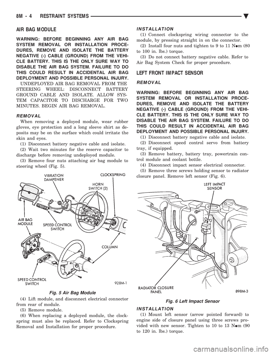
REMOVAL
When removing a deployed module, wear rubber
gloves, eye protection and a long sleeve shirt as de-
posits may be on the surface which could irritate the
skin and eyes. (1) Disconnect battery negative cable and isolate.
(2) Wait two minutes for the reserve capacitor to
discharge before removing undeployed module. (3) Remove four nuts attaching air bag module to
steering wheel (Fig. 5).
(4) Lift module, and disconnect electrical connector
from rear of module. (5) Remove module.
(6) When replacing a deployed module, the clock-
spring must also be replaced. Refer to Clockspring
Removal and Installation for proper procedure.
INSTALLATION
(1) Connect clockspring wiring connector to the
module, by pressing straight in on the connector. (2) Install four nuts and tighten to 9 to 11 N Im (80
to 100 in. lbs.) torque. (3) Do not connect battery negative cable. Refer to
Air Bag System Check for proper procedure.
LEFT FRONT IMPACT SENSOR
REMOVAL
WARNING: BEFORE BEGINNING ANY AIR BAG
SYSTEM REMOVAL OR INSTALLATION PROCE-
DURES, REMOVE AND ISOLATE THE BATTERY
NEGATIVE (-) CABLE (GROUND) FROM THE VEHI-
CLE BATTERY. THIS IS THE ONLY SURE WAY TO
DISABLE THE AIR BAG SYSTEM. FAILURE TO DO
THIS COULD RESULT IN ACCIDENTAL AIR BAG
DEPLOYMENT AND POSSIBLE PERSONAL INJURY. (1) Disconnect battery negative cable and isolate.
(2) Disconnect speed control servo from battery
tray, if equipped. (3) Remove battery, battery tray, powertrain con-
trol module and coolant bottle. (4) Disconnect impact sensor electrical connector.
(5) Remove three screws holding sensor to radiator
closure panel. Remove left sensor (Fig. 6).
INSTALLATION
(1) Mount left sensor (arrow pointed forward) to
engine side of closure panel using three screws pro-
vided with new sensor. Tighten to 10 to 13 N Im (90
to 120 in. lbs.) torque.
Fig. 5 Air Bag Module
Fig. 6 Left Impact Sensor
8M - 4 RESTRAINT SYSTEMS Ä
Page 787 of 2438

AC BODY C,D
Caption Fig.
Air Suspension Wiring ..........................4
Body Left Side Wiring ...........................8
Body Right Side Wiring ..........................9
Cellular Phone Wiring ...........................7
Deck Lid Wiring ..............................5
Door Wiring (Body) ...........................10
Door Wiring (Front) ...........................11
Door Wiring (Rear) ............................12
Engine Wiring 2.5L ............................27
Engine Wiring 3.0L ............................28
Engine Wiring 3.3L, 3.8L ........................29
Engine Compartment Wiring 2.5L ................18, 19
Engine Compartment Wiring 3.0L .............20, 22, 23
Engine Compartment Wiring 3.3L, 3.8L ..........21, 22, 23Caption Fig.
Front End Lighting (Aero Headlamps) ................32
Front End Lighting (Concealed Headlamps) ............33
Ground Strap Locations .........................30
Heated Rear Window Wiring .......................6
Instrument Panel Wiring .................. .13, 14, 15
Load Leveling Wiring ...........................3
Radiator Fan Assembly .........................31
Rear End Wiring (Chrysler) .......................1
Rear End Wiring (Dodge) ........................2
Steering Column Wiring .........................16
Transmission Wiring 2.5L .......................24
Transmission WIring 3.0L .......................25
Transmission Wiring 3.3L, 3.8L ....................26
Underhood Lamp Wiring ........................17
Ä WIRING AND COMPONENT IDENTIFICATION 8W - 37
Page 861 of 2438

AY BODY-C
Caption Fig.
Air Suspension Wiring ..........................3
Body Left Side Wiring ...........................8
Body Right Side Wiring ..........................9
Cellular Phone Wiring ...........................7
Deck Lid Wiring ..............................5
Door Wiring (Body) ...........................10
Door Wiring (Front) ...........................11
Door Wiring (Rear) ............................12
Engine Wiring 3.3L and 3.8L .....................23
Engine Compartment Wiring 3.3L and 3.8L .......18, 19, 20Caption Fig.
Front End Lighting ............................24
Ground Strap Locations .........................6
Heated Rear Window Wiring .......................4
Instrument Panel Wiring .................. .13, 14, 15
Load Leveling Wiring ...........................2
Radiator Fan Assembly .........................21
Rear End Wiring ..............................1
Steering Column Wiring .........................16
Transmission Wiring 3.3L and 3.8L .................22
Underhood Lamp Wiring ........................17
Ä WIRING AND COMPONENT IDENTIFICATION 8W - 111