1993 CHEVROLET PLYMOUTH ACCLAIM flat tire
[x] Cancel search: flat tirePage 304 of 2438

WHEEL SPEED SENSORS
One Wheel Speed Sensor (WSS), is located at each
wheel (Fig. 5 and 6), and sends a small AC signal to the
control module CAB. This signal is generated by mag-
netic induction. The magnetic induction is created,
when a toothed sensor ring (Tone Wheel) (Fig. 7) passes
a stationary magnetic Wheel Speed Sensor. The CAB
converts the AC signal generated at each wheel into a
digital signal. If a wheel locking tendency is detected,
the CAB will then modulate hydraulic pressure to pre-
vent the wheel or wheels from locking.
The front Wheel Speed Sensor is attached to a boss
in the steering knuckle (Fig. 5). The tone wheel is
part of the outboard constant velocity joint (Fig. 5). The rear Wheel Speed Sensor is mounted to the cal-
iper adapter (Fig. 6) and the rear tone wheel is an
integral part of the rear wheel hub (Fig. 7). The
speed sensor air gap is NOT adjustable.
The four Wheel Speed Sensors are serviced individ-
ually. The front Tone Wheels are serviced as an as-
sembly with the outboard constant velocity joint. The
rear Tone Wheels are serviced as an assembly with
the rear brake hub. Correct Antilock system operation is dependent on
the vehicle's wheel speed signals, that are generated
by the Wheel Speed Sensors. The vehicle's wheels
and tires must all be the same size and type to gen-
erate accurate signals. In addition, the tires must be
inflated to the recommended pressures for optimum
system operation. Variations in wheel and tire size
or significant variations in inflation pressure can
produce inaccurate wheel speed signals.
CONTROLLER ANTILOCK BRAKE CAB
The Antilock Brake Controller is a small micropro-
cessor based device which monitors the brake system
and controls the system while it functions in the An-
tilock mode. The CAB is mounted on the top of the
right front frame rail and uses a 60-way system con-
nector (Fig. 8). The power source for the CAB is
through the ignition switch in the Run or On posi-
tion. THE CONTROLLER ANTILOCK BRAKE
CAB IS NOT ON THE CCD BUS The primary functions of the CAB are:
(1) Detect wheel locking tendencies.
(2) Control fluid modulation to the brakes while in
Antilock mode. (3) Monitor the system for proper operation.
Fig. 5 Front Wheel Speed Sensor
Fig. 6 Rear Wheel Speed Sensor
Fig. 7 Rear Tone Wheel (Typical)
5 - 18 ANTILOCK 4 BRAKE SYSTEM Ä
Page 445 of 2438
When testing secondary cables for punctures and
cracks with an oscilloscope follow the equipment
manufacturers instructions. If an oscilloscope is not available, secondary cables
can be tested as follows:
CAUTION: Do not leave any one spark plug cable
disconnected any longer than necessary during test-
ing. Excessive heat could damage the catalytic con-
verter. Total test time must not exceed ten minutes.
(a) With the engine not running, connect one end
of a test probe to a good ground. Use a probe made of
insulated wire with insulated alligator clips on each
end. (b) With engine running, move test probe along
entire length of all cables (approximately 0 to 1/8
inch gap). If punctures or cracks are present there
will be a noticeable spark jump from the faulty area
to the probe. Check the coil cable the same way.
Replace cracked, leaking or faulty cables.
When replacing cables, install the new high
tension cable and nipple assembly over cap or
coil tower. When entering the terminal into the
tower, push lightly, then pinch the large diam-
eter of nipple to release air trapped between the
nipple and tower. Continue pushing on the cable
and nipple until cables are properly seated in the
cap towers. A snap should be heard as terminal
goes into place. Use the same procedure to install cable in coil tower.
Wipe the spark plug insulator clean before reinstalling
cable and cover. Use the following procedure when removing the high
tension cable from the spark plug. First, remove the
cable from the retaining bracket. Then grasp the ter-
minal as close as possible to the spark plug. Rotate the
cover and pull the cable straight back. Pulling on the
cable itself will damage the conductor and termi-
nal connection. Do not use pliers and do not pull
the cable at an angle. Doing so will damage the
insulation, cable terminal or the spark plug in-
sulator. Wipe spark plug insulator clean before
reinstalling cable and cover. Resistance type cable is identified by the words
Electronic Suppression printed on the cable jacket.
Use an ohmmeter to check resistance type cable for
open circuits, loose terminals or high resistance as
follows: (a) Remove cable from spark plug.
(b) Lift distributor cap from distributor with
cables intact. Do not remove cables from cap. The
cables must be removed from the spark plugs. (c) Connect the ohmmeter between spark plug end
terminal and the corresponding electrode inside the
cap, make sure ohmmeter probes are in good contact.
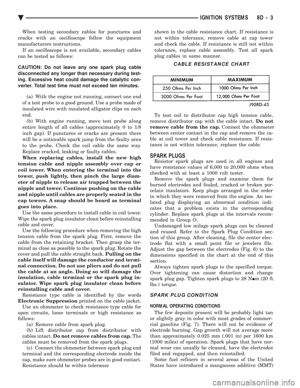
Resistance should be within tolerance shown in the cable resistance chart. If resistance is
not within tolerance, remove cable at cap tower
and check the cable. If resistance is still not within
tolerance, replace cable assembly. Test all spark
plug cables in same manner.
To test coil to distributor cap high tension cable,
remove distributor cap with the cable intact. Do not
remove cable from the cap. Connect the ohmmeter
between center contact in the cap and remove the ca-
ble at coil tower and check cable resistance. If resis-
tance is not within tolerance, replace the cable.
SPARK PLUGS
Resistor spark plugs are used in all engines and
have resistance values of 6,000 to 20,000 ohms when
checked with at least a 1000 volt tester. Remove the spark plugs and examine them for
burned electrodes and fouled, cracked or broken por-
celain insulators. Keep plugs arranged in the order
in which they were removed from the engine. An iso-
lated plug displaying an abnormal condition indi-
cates that a problem exists in the corresponding
cylinder. Replace spark plugs at the intervals recom-
mended in Group O. Undamaged low milage spark plugs can be cleaned
and reused. Refer to the Spark Plug Condition sec-
tion of this group. After cleaning, file the center elec-
trode flat with a small point file or jewelers file.
Adjust the gap between the electrodes (Fig. 6) to the
dimensions specified in the chart at the end of this
section. Always tighten spark plugs to the specified torque.
Over tightening can cause distortion and change
spark plug gap. Tighten spark plugs to 28 N Im (20 ft.
lbs.) torque.
SPARK PLUG CONDITION
NORMAL OPERATING CONDITIONS
The few deposits present will be probably light tan
or slightly gray in color with most grades of commer-
cial gasoline (Fig. 7). There will not be evidence of
electrode burning. Gap growth will not average more
than approximately 0.025 mm (.001 in) per 1600 km
(1000 miles) of operation. Spark plugs that have nor-
mal wear can usually be cleaned, have the electrodes
filed and regapped, and then reinstalled. Some fuel refiners in several areas of the United
States have introduced a manganese additive (MMT)
CABLE RESISTANCE CHART
Ä IGNITION SYSTEMS 8D - 3
Page 645 of 2438
EXTERIOR LAMP SWITCHES AND HEADLAMP ALIGNMENT INDEX
page page
Headlamp Adjustment Using Alignment Screen .... 3
Headlamp Alignment ....................... 3
Headlamp Alignment Preparation .............. 3 Headlamp Dimmer Switch
................... 3
Headlamp Switch .......................... 3
HEADLAMP SWITCH
Service procedures for the headlamp switch can be
found in Group 8E, Instrument Panel and Gauges. More
information can be found in Wiring Diagrams manual.
HEADLAMP DIMMER SWITCH
The headlamp dimmer switch is incorporated into
the turn signal switch. Proper procedures can be found
in Group 8J, Turn Signal and Flashers. More informa-
tion can be found in Group 8W, Wiring Diagrams.
HEADLAMP ALIGNMENT
Headlamps can be aligned using the screen method
provided in this section. Alignment Tool C4466-A or
equivalent can also be used. Refer to instructions
provided with the tool for proper procedures. The
preferred headlamp alignment setting is 0 for the
left/right adjustment and 0 for the up/down ad-
justment.
HEADLAMP ALIGNMENT PREPARATION
(1) Verify headlamp dimmer switch and high beam
indicator operation. (2) Inspect and correct damaged or defective compo-
nents that could interfere with proper headlamp align-
ment. (3) Verify proper tire inflation.
(4) Clean headlamp lenses.
(5) Verify that luggage area is not heavily loaded.
(6) Fuel tank should be FULL. Add 2.94 kg (6.5 lbs.)
of weight over the fuel tank for each estimated gallon of
missing fuel.
HEADLAMP ADJUSTMENT USING ALIGNMENT
SCREEN
ALIGNMENT SCREEN PREPARATION (FIG. 1 AND 2)
(1) Position vehicle on a level surface perpendicular
to a flat wall 7.62 meters (25 ft) away from front of
headlamp lens. (2) If necessary, tape a line on the floor 7.62 meters
(25 ft) away from and parallel to the wall.
(3) From the floor up 1.27 meters (5 ft), tape a line on
the wall at the centerline of the vehicle. Sight along the
centerline of the vehicle (from rear of vehicle forward) to
verify accuracy of the line placement.
(4) Rock vehicle side-to-side three times to allow
suspension to stabilize. (5) Jounce front suspension three times by pushing
downward on front bumper and releasing. (6) Measure the distance from the center of head-
lamp lens to the floor. Transfer measurement to the
alignment screen (with tape). Use this line for up/down
adjustment reference. (7) Measure distance from the centerline of the ve-
hicle to the center of each headlamp being aligned.
Transfer measurements to screen (with tape) to each
side of vehicle centerline. Use these lines for left/right
adjustment reference.
HEADLAMP ADJUSTMENT (FIG. 3, 4, 5, 6 OR 7)
A properly aimed low beam headlamp will project the
top edge of low beam hot spot on the alignment screen
from 50 mm (2 in.) above to 50 mm (2 in.) below the
headlamp centerline. The side-to-side left edge of low
beam hot spot should be from 50 mm (2 in.) left to
50mm (2 in.) right of headlamp centerline (Fig. 1). The
preferred headlamp alignment is 0 for the
up/down adjustment and 0 for the left/right ad-
justment. The high beams on a vehicle with aero
headlamps cannot be aligned. The high beam pattern
should be correct when the low beams are aligned
properly. To adjust headlamp alignment, rotate alignment
screws to achieve the specified low beam hot spot
pattern.
CAUTION: Do not cover an illuminated headlamp for
more then 15 seconds. Lamp will overheat and burn
or melt cover.
To adjust headlamps, rotate alignment screws to
achieve the specified high intensity pattern (Fig. 1 or
2).
FOG LAMP ALIGNMENT (FIG. 8)
Prepare an alignment screen. Refer to Alignment
Screen Preparation paragraph in this section. A prop-
erly aligned fog lamp will project a pattern on the
alignment screen 100 mm (4 in.) below the fog lamp
centerline and straight ahead.
Ä LAMPS 8L - 3
Page 1570 of 2438
REMOVE ALL SHIMS BEFORE REASSEM-
BLING ENGINE ALTERNATIVE METHOD Ð With the weight of
the crankshaft being supported by a jack under the
counterweight adjacent to the bearing being checked. (3) Place a piece of Plastigage across the entire
width of the bearing shell in the cap approximately
6.35 mm (1/4 inch) off center and away from the oil
holes (Fig. 2). (In addition, suspect areas can be
checked by placing the Plastigage in the suspect area).
Torque the bearing cap bolts of the bearing being
checked to the proper specifications. (4) Remove the bearing cap and compare the width
of the flattened Plastigage (Fig. 3) with the metric scale
provided on the package. Locate the band closest to the
same width. This band shows the amount of clearance
in thousandths of a millimeter. Differences in readings
between the ends indicate the amount of taper present.
Record all readings taken. Refer to Engine Specifica-
tions. Plastic-Gage generally is accompanied by
two scales. One scale is in inches, the other is a
metric scale. (5) Plastigage is available in a variety of clearance
ranges. The 0.025-0.076mm (.001-.003 inch) is usually
the most appropriate for checking engine bearing
proper specifications.
CONNECTING ROD BEARING CLEARANCE
Engine crankshaft bearing clearances can be deter-
mined by use of Plastigage or equivalent. The following
is the recommended procedure for the use of Plasti-
gage: (1) Rotate the crankshaft until the connecting rod to
be checked is at the bottom of its stroke. (2) Remove oil film from surface to be checked.
Plastigage is soluble in oil. (3) Place a piece of Plastigage across the entire
width of the bearing shell in the bearing cap approxi-
mately 6.35 mm (1/4 inch.) off center and away from
the oil hole (Fig. 2). In addition, suspect areas can be
checked by placing plastigage in the suspect area. (4) Before assembling the rod cap with Plastigage in
place, the crankshaft must be rotated until the con-
necting being checked starts moving toward the top of
the engine. Only then should the cap be assembled and
torqued to specifications. Do not rotate the crank-
shaft while assembling the cap or the Plastigage
may be smeared, giving inaccurate results. (5) Remove the bearing cap and compare the width
of the flattened Plastigage (Fig. 3) with the metric
scale provided on the package. Locate the band closest
to the same width. This band shows the amount
of clearance in thousandths of a millimeter. Differences
in readings between the ends indicate the amount
of taper present. Record all readings taken.
Refer to Engine Specifications. Plastigage generally is accompanied by two scales. One scale is in
inches, the other is a metric scale. (6) Plastigage is available in a variety of clearance
ranges. The 0.025-0.076mm (.001-.003 inch) is usually
the most appropriate for checking engine bearing
proper specifications.
LASH ADJUSTER (TAPPET) NOISE DIAGNOSIS
A tappet-like noise may be produced from several
items. Check the following items. (1) Engine oil level too high or too low. This may
cause aerated oil to enter the adjusters and cause them
to be spongy. (2) Insufficient running time after rebuilding cylin-
der head. Low speed running up to 1 hour may be
required. During this time, turn engine off and let set for a few
minutes before restarting. Repeat this several times
after engine has reached normal operating tempera-
ture. (3) Low oil pressure.
(4) The oil restrictor pressed into the vertical oil
passage to the cylinder head of Balance Shaft Engines
Only is plugged with debris. (5) Air ingested into oil due to broken or cracked oil
pump pick up. (6) Worn valve guides.
(7) Rocker arm ears contacting valve spring retainer
(2.2/2.5L engines). (8) Rocker arm loose, adjuster or tappet stuck or at
maximum extension and still leaves lash in the system. (9) Faulty lash adjuster or tappet.(a) Check for sponginess while still installed in
engine. Depress part of rocker arm just over adjuster
or pushrod . Normal adjusters should feel very firm.
Spongy adjusters can be depressed to the bottomed
position easily. (b) Remove suspected lash adjuster or tappet, pry
off retainer cap or snap ring and disassemble. Do
not reuse retainer caps . Do not interchange parts
and make sure that care and cleanliness is exercised
in the handling of parts. (c) Clean out dirt and varnish with solvent.
(d) Reassemble with engine oil.
(e) Check for sponginess.
(f) If still spongy, replace with new adjuster.
REPAIR OF DAMAGED OR WORN THREADS
Damaged or worn threads (including aluminum head
spark plug threads) can be repaired. Essentially, this
repair consists of drilling out worn or damaged
threads, tapping the hole with a special Heli-Coil (or
equivalent) Tap, and installing an insert into the
tapped hole. This brings the hole back to its original
thread size.
9 - 4 ENGINE Ä
Page 1709 of 2438
(13) Disconnect articulated exhaust pipe joint from
turbocharger housing. (14) Remove turbocharger coolant inlet line assem-
bly from engine (Fig. 11). (15) Lift turbocharger off manifold mounting studs
and lower assembly down and out of vehicle.
EXHAUST MANIFOLD
REMOVAL
Remove 9 exhaust manifold retaining fasteners and
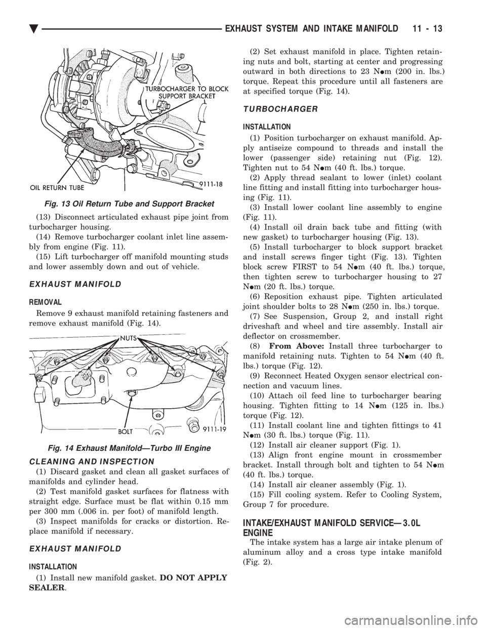
remove exhaust manifold (Fig. 14).
CLEANING AND INSPECTION
(1) Discard gasket and clean all gasket surfaces of
manifolds and cylinder head. (2) Test manifold gasket surfaces for flatness with
straight edge. Surface must be flat within 0.15 mm
per 300 mm (.006 in. per foot) of manifold length. (3) Inspect manifolds for cracks or distortion. Re-
place manifold if necessary.
EXHAUST MANIFOLD
INSTALLATION
(1) Install new manifold gasket. DO NOT APPLY
SEALER . (2) Set exhaust manifold in place. Tighten retain-
ing nuts and bolt, starting at center and progressing
outward in both directions to 23 N Im (200 in. lbs.)
torque. Repeat this procedure until all fasteners are
at specified torque (Fig. 14).
TURBOCHARGER
INSTALLATION
(1) Position turbocharger on exhaust manifold. Ap-
ply antiseize compound to threads and install the
lower (passenger side) retaining nut (Fig. 12).
Tighten nut to 54 N Im (40 ft. lbs.) torque.
(2) Apply thread sealant to lower (inlet) coolant
line fitting and install fitting into turbocharger hous-
ing (Fig. 11). (3) Install lower coolant line assembly to engine
(Fig. 11). (4) Install oil drain back tube and fitting (with
new gasket) to turbocharger housing (Fig. 13). (5) Install turbocharger to block support bracket
and install screws finger tight (Fig. 13). Tighten
block screw FIRST to 54 N Im (40 ft. lbs.) torque,
then tighten screw to turbocharger housing to 27
N Im (20 ft. lbs.) torque.
(6) Reposition exhaust pipe. Tighten articulated
joint shoulder bolts to 28 N Im (250 in. lbs.) torque.
(7) See Suspension, Group 2, and install right
driveshaft and wheel and tire assembly. Install air
deflector on crossmember. (8) From Above: Install three turbocharger to
manifold retaining nuts. Tighten to 54 N Im (40 ft.
lbs.) torque (Fig. 12). (9) Reconnect Heated Oxygen sensor electrical con-
nection and vacuum lines. (10) Attach oil feed line to turbocharger bearing
housing. Tighten fitting to 14 N Im (125 in. lbs.)
torque (Fig. 12). (11) Install coolant line and tighten fittings to 41
N Im (30 ft. lbs.) torque (Fig. 11).
(12) Install air cleaner support (Fig. 1).
(13) Align front engine mount in crossmember
bracket. Install through bolt and tighten to 54 N Im
(40 ft. lbs.) torque. (14) Install air cleaner assembly (Fig. 1).
(15) Fill cooling system. Refer to Cooling System,
Group 7 for procedure.
INTAKE/EXHAUST MANIFOLD SERVICEÐ3.0L
ENGINE
The intake system has a large air intake plenum of
aluminum alloy and a cross type intake manifold
(Fig. 2).
Fig. 13 Oil Return Tube and Support Bracket
Fig. 14 Exhaust ManifoldÐTurbo III Engine
Ä EXHAUST SYSTEM AND INTAKE MANIFOLD 11 - 13
Page 2010 of 2438
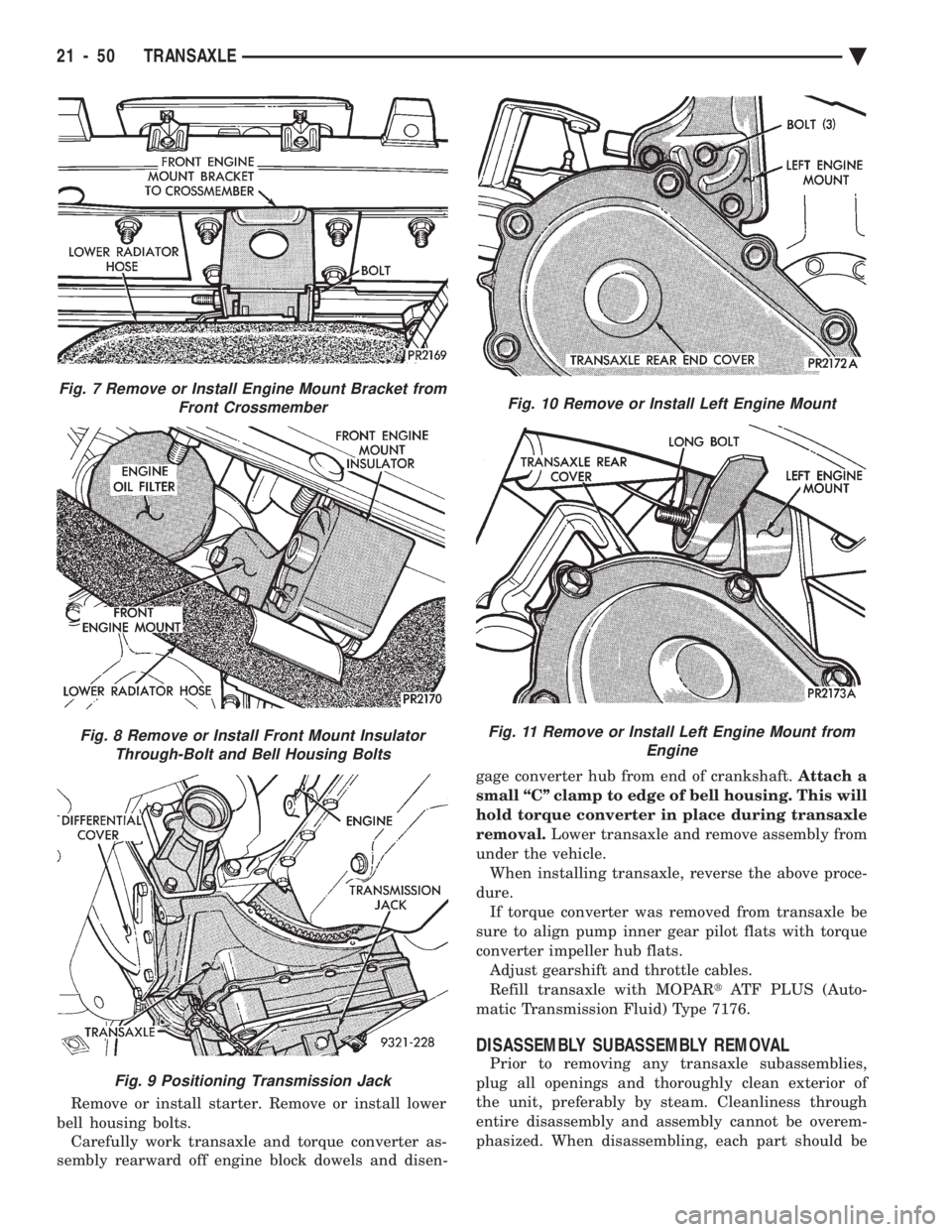
Remove or install starter. Remove or install lower
bell housing bolts. Carefully work transaxle and torque converter as-
sembly rearward off engine block dowels and disen- gage converter hub from end of crankshaft.
Attach a
small ``C'' clamp to edge of bell housing. This will
hold torque converter in place during transaxle
removal. Lower transaxle and remove assembly from
under the vehicle. When installing transaxle, reverse the above proce-
dure. If torque converter was removed from transaxle be
sure to align pump inner gear pilot flats with torque
converter impeller hub flats. Adjust gearshift and throttle cables.
Refill transaxle with MOPAR tATF PLUS (Auto-
matic Transmission Fluid) Type 7176.
DISASSEMBLY SUBASSEMBLY REMOVAL
Prior to removing any transaxle subassemblies,
plug all openings and thoroughly clean exterior of
the unit, preferably by steam. Cleanliness through
entire disassembly and assembly cannot be overem-
phasized. When disassembling, each part should be
Fig. 7 Remove or Install Engine Mount Bracket from Front Crossmember
Fig. 8 Remove or Install Front Mount InsulatorThrough-Bolt and Bell Housing Bolts
Fig. 9 Positioning Transmission Jack
Fig. 10 Remove or Install Left Engine Mount
Fig. 11 Remove or Install Left Engine Mount from Engine
21 - 50 TRANSAXLE Ä
Page 2149 of 2438
WHEELSÐTIRES
CONTENTS
page page
SPECIFICATIONS ........................ 8
TIRE SERVICE PROCEDURES .............. 1 WHEELS SERVICE PROCEDURES
........... 6
TIRE SERVICE PROCEDURES INDEX
page page
Cleaning of Tires .......................... 1
General Information ........................ 1
Pressure Gauges ......................... 2
Radial-Ply Tires ........................... 1
Repairing Leaks .......................... 3
Rotation ................................ 3 Spare TireÐCompact
...................... 1
Tire Inflation Pressures ..................... 2
Tire Noise or Vibration ..................... 3
Tire Wear Patterns ........................ 3
Tread Wear Indicators ...................... 3
GENERAL INFORMATION
Throughout this group, references may be made to a
particular vehicle by letter or number designation. A
chart showing the breakdown of these designations is
included in the Introduction Section. Tires are designed for the vehicle and provide the
best overall performance for normal operation. The
ride and handling characteristics match the vehicle's
requirements. With proper care they will give excellent
reliability traction, skid resistance and tread life. They
have load carrying capacity, when properly inflated, to
operate at loads up to the specified Maximum Vehicle
Capacity. Driving habits have more effect on tire life than any
other factor. Careful drivers will obtain, in most cases,
much greater mileage than severe or careless drivers. A
few of the driving habits which will shorten the life of
any tire are:
² Rapid acceleration and deceleration
² Severe application of brakes
² High-speed driving
² Taking turns at excessive speeds
² Striking curbs and other obstacles
Radial ply tires can be more susceptible to irregular
tread wear. It is very important to follow the tire
rotation interval shown in the section on Tire
Rotation to achieve a greater tread life potential.
RADIAL-PLY TIRES
Radial-ply tires improve handling, tread life, and
ride quality and decrease rolling resistance. Radial-ply tires must always be used in sets of four
and under no circumstances should they be used on
the front only. However, they may be mixed with temporary spare tires when necessary,
but reduced speeds are recommended. Radial-ply tires have the same load carrying capac-
ity as other types of tires of the same size. They also
use the same recommended inflation pressures.
SPARE TIREÐCOMPACT
The compact spare tire is designed for emergency
use only. The original tire should be repaired and re-
installed at the first opportunity. Refer to Owner's
Manual for complete details.
TIRE CHAINS
Tire snow chains may be used on certainmodels.
Refer to Owner's Manual for more information.
CLEANING OF TIRES
Remove protective coating on tires before delivery
of vehicle, otherwise it could cause deterioration of
tires. Remove protective coating by applying warm wa-
ter, letting it soak one minute, and then scrubbing
the coating away with a soft bristle brush. Steam cleaning may also be used for cleaning.
DO NOT use gasoline or wire brush for cleaning.
DO NOT use mineral oil or an oil-based solvent.
Ä WHEELSÐTIRES 22 - 1
Page 2150 of 2438
PRESSURE GAUGES
High quality dial type air pressure gauges are rec-
ommended. After checking pressure with the gauge,
replace valve caps and tighten finger tight.
TIRE INFLATION PRESSURES
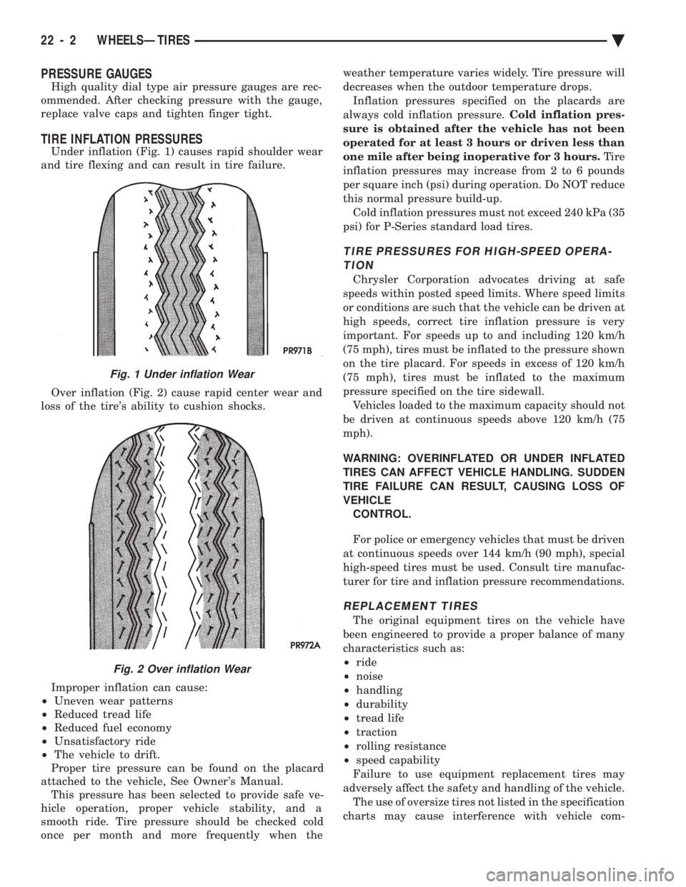
Under inflation (Fig. 1) causes rapid shoulder wear
and tire flexing and can result in tire failure.
Over inflation (Fig. 2) cause rapid center wear and
loss of the tire's ability to cushion shocks.
Improper inflation can cause:
² Uneven wear patterns
² Reduced tread life
² Reduced fuel economy
² Unsatisfactory ride
² The vehicle to drift.
Proper tire pressure can be found on the placard
attached to the vehicle, See Owner's Manual. This pressure has been selected to provide safe ve-
hicle operation, proper vehicle stability, and a
smooth ride. Tire pressure should be checked cold
once per month and more frequently when the weather temperature varies widely. Tire pressure will
decreases when the outdoor temperature drops.
Inflation pressures specified on the placards are
always cold inflation pressure. Cold inflation pres-
sure is obtained after the vehicle has not been
operated for at least 3 hours or driven less than
one mile after being inoperative for 3 hours. Tire
inflation pressures may increase from 2 to 6 pounds
per square inch (psi) during operation. Do NOT reduce
this normal pressure build-up. Cold inflation pressures must not exceed 240 kPa (35
psi) for P-Series standard load tires.
TIRE PRESSURES FOR HIGH-SPEED OPERA- TION
Chrysler Corporation advocates driving at safe
speeds within posted speed limits. Where speed limits
or conditions are such that the vehicle can be driven at
high speeds, correct tire inflation pressure is very
important. For speeds up to and including 120 km/h
(75 mph), tires must be inflated to the pressure shown
on the tire placard. For speeds in excess of 120 km/h
(75 mph), tires must be inflated to the maximum
pressure specified on the tire sidewall. Vehicles loaded to the maximum capacity should not
be driven at continuous speeds above 120 km/h (75
mph).
WARNING: OVERINFLATED OR UNDER INFLATED
TIRES CAN AFFECT VEHICLE HANDLING. SUDDEN
TIRE FAILURE CAN RESULT, CAUSING LOSS OF
VEHICLE CONTROL.
For police or emergency vehicles that must be driven
at continuous speeds over 144 km/h (90 mph), special
high-speed tires must be used. Consult tire manufac-
turer for tire and inflation pressure recommendations.
REPLACEMENT TIRES
The original equipment tires on the vehicle have
been engineered to provide a proper balance of many
characteristics such as:
² ride
² noise
² handling
² durability
² tread life
² traction
² rolling resistance
² speed capability
Failure to use equipment replacement tires may
adversely affect the safety and handling of the vehicle. The use of oversize tires not listed in the specification
charts may cause interference with vehicle com-
Fig. 1 Under inflation Wear
Fig. 2 Over inflation Wear
22 - 2 WHEELSÐTIRES Ä