1993 CHEVROLET DYNASTY oil level
[x] Cancel search: oil levelPage 1667 of 2438
(2) Loosen the right engine mount insulator yoke
screw and 2 turns on yoke nut, then loosen the front
engine mount bracket to front crossmember screws and
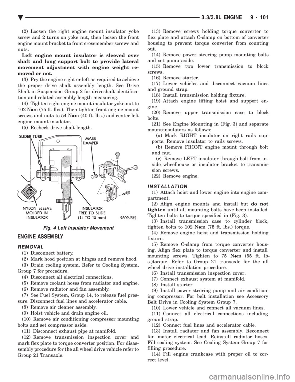
nuts. Left engine mount insulator is sleeved over
shaft and long support bolt to provide lateral
movement adjustment with engine weight re-
moved or not. (3) Pry the engine right or left as required to achieve
the proper drive shaft assembly length. See Drive
Shaft in Suspension Group 2 for driveshaft identifica-
tion and related assembly length measuring. (4) Tighten right engine mount insulator yoke nut to
102 N Im (75 ft. lbs.). Then tighten front engine mount
screws and nuts to 54 N Im (40 ft. lbs.) and center left
engine mount insulator. (5) Recheck drive shaft length.
ENGINE ASSEMBLY
REMOVAL
(1) Disconnect battery.
(2) Mark hood position at hinges and remove hood.
(3) Drain cooling system. Refer to Cooling System,
Group 7 for procedure. (4) Disconnect all electrical connections.
(5) Remove coolant hoses from radiator and engine.
(6) Remove radiator and fan assembly.
(7) See Fuel System, Group 14, to release fuel pres-
sure. Disconnect fuel lines and accelerator cable. (8) Remove air cleaner assembly.
(9) Hoist vehicle and drain engine oil.
(10) Remove air conditioning compressor mounting
bolts and set compressor aside. (11) Disconnect exhaust pipe at manifold.
(12) Remove transmission inspection cover and
mark flex plate to torque converter position. For disas-
sembly procedure for the all wheel drive vehicle refer to
Group 21 Transaxle. (13) Remove screws holding torque converter to
flex plate and attach C-clamp on bottom of converter
housing to prevent torque converter from counting
out. (14) Remove power steering pump mounting bolts
and set pump aside. (15) Remove two lower transmission to block
screws. (16) Remove starter.
(17) Lower vehicles and disconnect vacuum lines
and ground strap. (18) Install transmission holding fixture.
(19) Attach engine lifting hoist and support en-
gine. (20) Remove upper transmission case to block
bolts. (21) See Engine Mounting in (Fig. 3) and separate
mount/insulators as follows: (a) Mark RIGHT insulator on right rails sup-
ports. Remove insulator to rails screws. (b) Remove FRONT engine mount through bolt
and nut. (c) Remove LEFT insulator through bolt from in-
side wheelhouse or insulator bracket to transmis-
sion screws.
(22) Remove engine.
INSTALLATION
(1) Attach hoist and lower engine into engine com-
partment. (2) Align engine mounts and install but do not
tighten until all mounting bolts have been installed.
Tighten bolts to torque specified in (Fig. 3). (3) Install transmission case to cylinder block,
tighten bolts to 102 N Im (75 ft. lbs.) torque.
(4) Remove engine hoist and transmission holding
fixture. (5) Remove C-clamp from torque converter hous-
ing. Align flex plate to torque converter and install
mounting screws. Tighten to 75 N Im (55 ft. lb-
s.)torque. Refer to Group 21 transaxle for the all
wheel drive installation procedure. (6) Install transmission inspection cover.
(7) Connect exhaust system at manifold.
(8) Install starter.
(9) Install power steering pump and air condition-
ing compressor. For belt installation see Accessory
Belt Drive in Cooling System Group 7. (10) Lower vehicle and connect all vacuum lines.
(11) Connect all electrical connections including
ground strap. (12) Connect fuel lines and accelerator cable.
(13) Install radiator and fan assembly. Reconnect
fan motor electrical lead. Reinstall radiator hoses.
Fill cooling system. See Cooling System Group 7 for
filling procedure. (14) Fill engine crankcase with proper oil to cor-
rect level.
Fig. 4 Left Insulator Movement
Ä 3.3/3.8L ENGINE 9 - 101
Page 1674 of 2438
(15) Install rocker arm covers tighten screws to 14
N Im (120 in. lbs.) and connector to ignition coils.
(16) Install Intake Manifold; Refer to Intake Mani-
fold Installation 3.3/3.8L Engine, Group 11 Exhaust
System and Intake Manifold.
HYDRAULIC TAPPETS
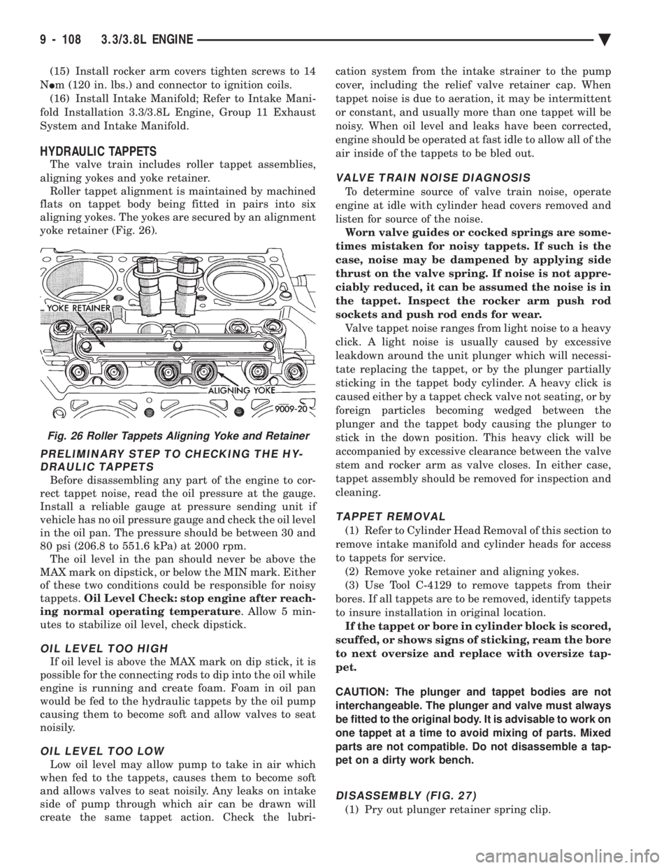
The valve train includes roller tappet assemblies,
aligning yokes and yoke retainer. Roller tappet alignment is maintained by machined
flats on tappet body being fitted in pairs into six
aligning yokes. The yokes are secured by an alignment
yoke retainer (Fig. 26).
PRELIMINARY STEP TO CHECKING THE HY- DRAULIC TAPPETS
Before disassembling any part of the engine to cor-
rect tappet noise, read the oil pressure at the gauge.
Install a reliable gauge at pressure sending unit if
vehicle has no oil pressure gauge and check the oil level
in the oil pan. The pressure should be between 30 and
80 psi (206.8 to 551.6 kPa) at 2000 rpm. The oil level in the pan should never be above the
MAX mark on dipstick, or below the MIN mark. Either
of these two conditions could be responsible for noisy
tappets. Oil Level Check: stop engine after reach-
ing normal operating temperature . Allow 5 min-
utes to stabilize oil level, check dipstick.
OIL LEVEL TOO HIGH
If oil level is above the MAX mark on dip stick, it is
possible for the connecting rods to dip into the oil while
engine is running and create foam. Foam in oil pan
would be fed to the hydraulic tappets by the oil pump
causing them to become soft and allow valves to seat
noisily.
OIL LEVEL TOO LOW
Low oil level may allow pump to take in air which
when fed to the tappets, causes them to become soft
and allows valves to seat noisily. Any leaks on intake
side of pump through which air can be drawn will
create the same tappet action. Check the lubri- cation system from the intake strainer to the pump
cover, including the relief valve retainer cap. When
tappet noise is due to aeration, it may be intermittent
or constant, and usually more than one tappet will be
noisy. When oil level and leaks have been corrected,
engine should be operated at fast idle to allow all of the
air inside of the tappets to be bled out.
VALVE TRAIN NOISE DIAGNOSIS
To determine source of valve train noise, operate
engine at idle with cylinder head covers removed and
listen for source of the noise. Worn valve guides or cocked springs are some-
times mistaken for noisy tappets. If such is the
case, noise may be dampened by applying side
thrust on the valve spring. If noise is not appre-
ciably reduced, it can be assumed the noise is in
the tappet. Inspect the rocker arm push rod
sockets and push rod ends for wear. Valve tappet noise ranges from light noise to a heavy
click. A light noise is usually caused by excessive
leakdown around the unit plunger which will necessi-
tate replacing the tappet, or by the plunger partially
sticking in the tappet body cylinder. A heavy click is
caused either by a tappet check valve not seating, or by
foreign particles becoming wedged between the
plunger and the tappet body causing the plunger to
stick in the down position. This heavy click will be
accompanied by excessive clearance between the valve
stem and rocker arm as valve closes. In either case,
tappet assembly should be removed for inspection and
cleaning.
TAPPET REMOVAL
(1) Refer to Cylinder Head Removal of this section to
remove intake manifold and cylinder heads for access
to tappets for service. (2) Remove yoke retainer and aligning yokes.
(3) Use Tool C-4129 to remove tappets from their
bores. If all tappets are to be removed, identify tappets
to insure installation in original location. If the tappet or bore in cylinder block is scored,
scuffed, or shows signs of sticking, ream the bore
to next oversize and replace with oversize tap-
pet.
CAUTION: The plunger and tappet bodies are not
interchangeable. The plunger and valve must always
be fitted to the original body. It is advisable to work on
one tappet at a time to avoid mixing of parts. Mixed
parts are not compatible. Do not disassemble a tap-
pet on a dirty work bench.
DISASSEMBLY (FIG. 27)
(1) Pry out plunger retainer spring clip.
Fig. 26 Roller Tappets Aligning Yoke and Retainer
9 - 108 3.3/3.8L ENGINE Ä
Page 1677 of 2438
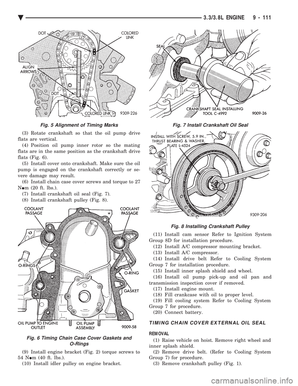
(3) Rotate crankshaft so that the oil pump drive
flats are vertical. (4) Position oil pump inner rotor so the mating
flats are in the same position as the crankshaft drive
flats (Fig. 6). (5) Install cover onto crankshaft. Make sure the oil
pump is engaged on the crankshaft correctly or se-
vere damage may result. (6) Install chain case cover screws and torque to 27
N Im (20 ft. lbs.).
(7) Install crankshaft oil seal (Fig. 7).
(8) Install crankshaft pulley (Fig. 8).
(9) Install engine bracket (Fig. 2) torque screws to
54 N Im (40 ft. lbs.).
(10) Install idler pulley on engine bracket. (11) Install cam sensor Refer to Ignition System
Group 8D for installation procedure. (12) Install A/C compressor mounting bracket.
(13) Install A/C compressor.
(14) Install drive belt Refer to Cooling System
Group 7 for installation procedure. (15) Install inner splash shield and wheel.
(16) Install oil pump pick-up and oil pan and
transmission inspection cover if removed. (17) Install engine mount.
(18) Fill crankcase with oil to proper level.
(19) Fill cooling system Refer to Cooling System
Group 7 for procedure. (20) Connect battery.
TIMING CHAIN COVER EXTERNAL OIL SEAL
REMOVAL
(1) Raise vehicle on hoist. Remove right wheel and
inner splash shield. (2) Remove drive belt. (Refer to Cooling System
Group 7) for procedure. (3) Remove crankshaft pulley (Fig. 1).
Fig. 5 Alignment of Timing Marks
Fig. 6 Timing Chain Case Cover Gaskets and O-Rings
Fig. 7 Install Crankshaft Oil Seal
Fig. 8 Installing Crankshaft Pulley
Ä 3.3/3.8L ENGINE 9 - 111
Page 1688 of 2438
ENGINE LUBRICATION SYSTEM
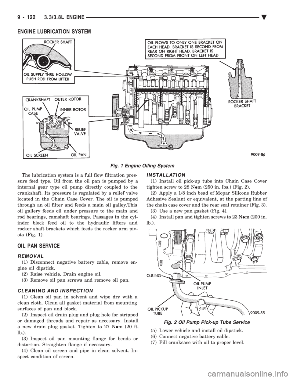
The lubrication system is a full flow filtration pres-
sure feed type. Oil from the oil pan is pumped by a
internal gear type oil pump directly coupled to the
crankshaft. Its pressure is regulated by a relief valve
located in the Chain Case Cover. The oil is pumped
through an oil filter and feeds a main oil galley.This
oil gallery feeds oil under pressure to the main and
rod bearings, camshaft bearings. Passages in the cyl-
inder block feed oil to the hydraulic lifters and
rocker shaft brackets which feeds the rocker arm piv-
ots (Fig. 1).
OIL PAN SERVICE
REMOVAL
(1) Disconnect negative battery cable, remove en-
gine oil dipstick. (2) Raise vehicle. Drain engine oil.
(3) Remove oil pan screws and remove oil pan.
CLEANING AND INSPECTION
(1) Clean oil pan in solvent and wipe dry with a
clean cloth. Clean all gasket material from mounting
surfaces of pan and block. (2) Inspect oil drain plug and plug hole for stripped
or damaged threads and repair as necessary. Install
a new drain plug gasket. Tighten to 27 N Im (20 ft.
lb.). (3) Inspect oil pan mounting flange for bends or
distortion. Straighten flange if necessary. (4) Clean oil screen and pipe in clean solvent. In-
spect condition of screen.
INSTALLATION
(1) Install oil pick-up tube into Chain Case Cover
tighten screw to 28 N Im (250 in. lbs.) (Fig. 2).
(2) Apply a 1/8 inch bead of Mopar Silicone Rubber
Adhesive Sealant or equivalent, at the parting line of
the chain case cover and the rear seal retainer (Fig. 3). (3) Use a new pan gasket (Fig. 4).
(4) Install pan and tighten screws to 23 N Im (200 in.
lb.).
(5) Lower vehicle and install oil dipstick.
(6) Connect negative battery cable.
(7) Fill crankcase with oil to proper level.
Fig. 1 Engine Oiling System
Fig. 2 Oil Pump Pick-up Tube Service
9 - 122 3.3/3.8L ENGINE Ä
Page 1700 of 2438
SERVICE PROCEDURES INDEX
page page
Exhaust Pipes, Mufflers and Tailpipes .......... 4
Intake and Exhaust Manifolds ServiceÐTBI Engine.6Intake and Exhaust ManifoldsÐFlexible Fuel Engine.7
Intake and Exhaust ManifoldsÐTBI Engine ...... 5
Intake/Exhaust Manifold ServiceÐ3.0L Engine . . . 13
Intake/Exhaust Manifold ServiceÐ3.3/3.8L Engines.19
Intake/Exhaust Manifolds and Turbocharger ServiceÐTurbo III Engine .................. 9
Intake/Exhaust Manifolds ServiceÐFlexible Fuel Engines ............................... 7
EXHAUST PIPES, MUFFLERS AND TAILPIPES
REMOVAL
(1) Raise vehicle on hoist and apply penetrating oil
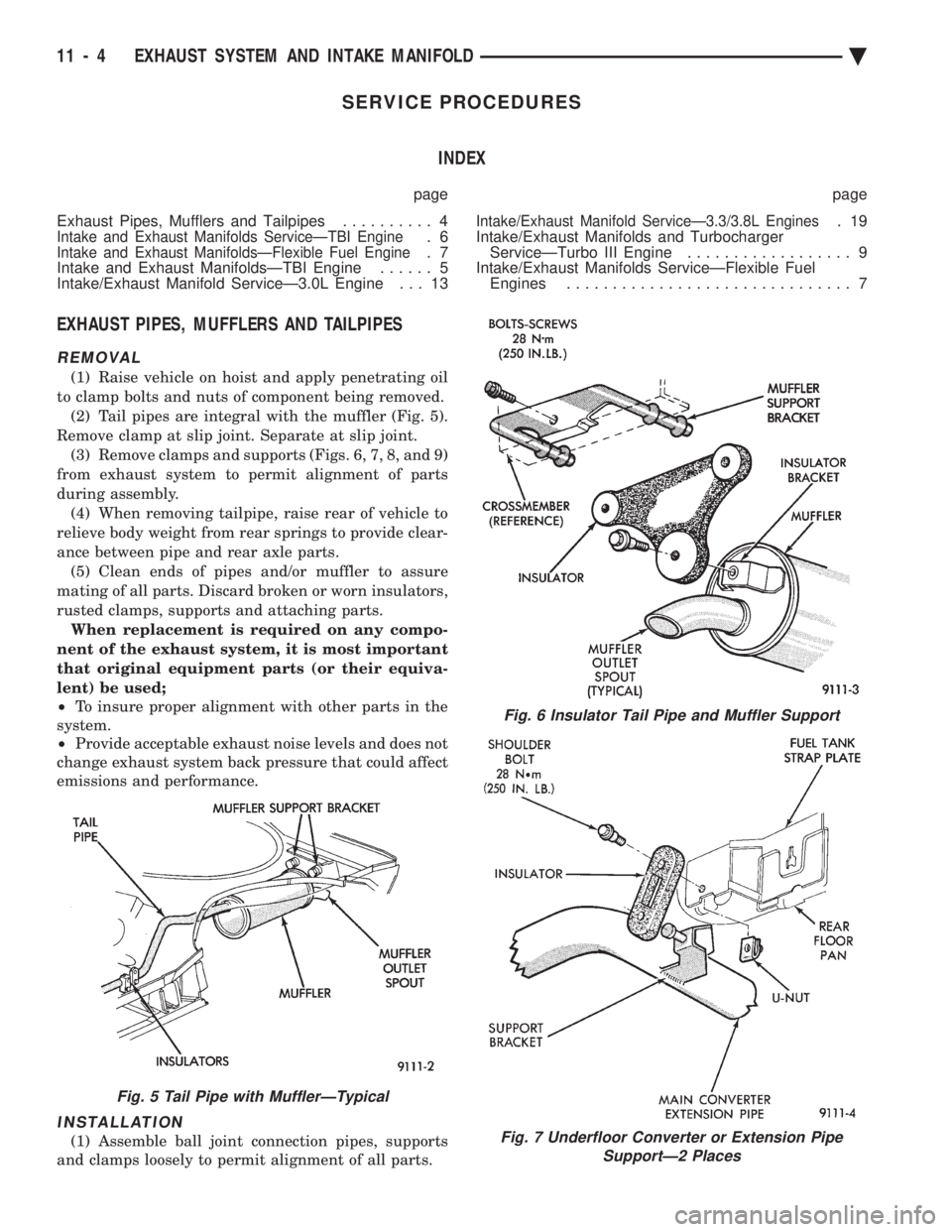
to clamp bolts and nuts of component being removed. (2) Tail pipes are integral with the muffler (Fig. 5).
Remove clamp at slip joint. Separate at slip joint. (3) Remove clamps and supports (Figs. 6, 7, 8, and 9)
from exhaust system to permit alignment of parts
during assembly. (4) When removing tailpipe, raise rear of vehicle to
relieve body weight from rear springs to provide clear-
ance between pipe and rear axle parts. (5) Clean ends of pipes and/or muffler to assure
mating of all parts. Discard broken or worn insulators,
rusted clamps, supports and attaching parts. When replacement is required on any compo-
nent of the exhaust system, it is most important
that original equipment parts (or their equiva-
lent) be used;
² To insure proper alignment with other parts in the
system.
² Provide acceptable exhaust noise levels and does not
change exhaust system back pressure that could affect
emissions and performance.
INSTALLATION
(1) Assemble ball joint connection pipes, supports
and clamps loosely to permit alignment of all parts.
Fig. 6 Insulator Tail Pipe and Muffler Support
Fig. 7 Underfloor Converter or Extension Pipe SupportÐ2 Places
Fig. 5 Tail Pipe with MufflerÐTypical
11 - 4 EXHAUST SYSTEM AND INTAKE MANIFOLD Ä
Page 1758 of 2438
INSTALLATION
WARNING: FUEL TANKS DESIGNED FOR GASO-
LINE ONLY VEHICLES CANNOT BE USED ON
FLEXIBLE FUEL AA-BODY VEHICLES. WHEN SER-
VICING THE FUEL SYSTEM OF A FLEXIBLE FUEL
VEHICLE, ONLY USE ORIGINAL EQUIPMENT OR
EQUIVALENT REPLACEMENT COMPONENTS. (1) Position fuel tank on transmission jack. Con-
nect vapor separator/rollover valve hose and position
insulator pad on fuel tank. Position vapor vent so
that it is not pinched between tank and floor pan
during installation. (2) Raise tank and fuel filler tube carefully into
position. Use a light coating of power steering fluid
to ease fuel filler tube installation. Ensure filler tube
grommet is not damaged. Verify that the tube is in-
stalled correctly. (3) Tighten fuel tank strap nuts to 23 N Im (250 in.
lbs.) torque. Remove transmission jack. Ensure
straps are not twisted or bent. (4) Lubricate the metal tubes on the fuel pump
with clean 30 weight engine oil. Install the quick
connect fuel fittings. Refer to Quick Connect Fittings
in the Fuel Delivery section of this Group. (5) Attach electrical connector to fuel pump mod-
ule and level sensor unit. (6) Lower the vehicle.
(7) Attach filler tube to filler neck opening in
quarter panel. Tighten quarter panel screws to 2
N Im (17 in. lbs.) torque.
(8) Fill fuel tank, install filler cap, and connect
battery cable.
CAUTION: When using the ASD Fuel System Test,
the Auto Shutdown (ASD) Relay remains energized
for either 7 minutes, until the test is stopped, or un-
til the ignition switch is turned to the Off position.
(9) Use the DRBII scan tool ASD Fuel System Test
to pressurize the fuel system. Check for leaks.
FUEL PUMP MODULE
Refer to the Fuel Delivery section of this group.
METHANOL CONCENTRATION SENSOR
Refer to the Fuel Delivery section of this group.
FUEL RESERVOIR
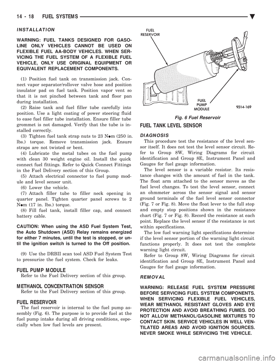
The fuel reservoir is internal to the fuel pump as-
sembly (Fig. 6). The purpose is to provide fuel at the
fuel pump intake during all driving conditions, espe-
cially when low fuel levels are present.
FUEL TANK LEVEL SENSOR
DIAGNOSIS
This procedure test the resistance of the level sen-
sor itself. It does not test the level sensor circuit. Re-
fer to Group 8W, Wiring Diagrams for circuit
identification and Group 8E, Instrument Panel and
Gauges for fuel gauge information. The level sensor is a variable resistor. Its resis-
tance changes with the amount of fuel in the tank.
The float arm attached to the sensor moves as the
fuel level changes. To test the level sensor, connect
an ohmmeter across the sensor signal and sensor
ground terminals of the fuel level sensor connector
(Fig. 7 or Fig. 8). Move the float lever to the full stop
and empty stop positions shown in the resistance
chart (Fig. 7 or Fig. 8). Record the resistance at each
point. Replace the level sensor if the resistance is not
within specifications. The low fuel warning light specifications determine
if the level sensor portion of the warning light circuit
functions properly. It does not test the complete
warning light circuit. Refer to Group 8W, Wiring Diagrams for circuit
identification and Group 8E, Instrument Panel and
Gauges for fuel gauge information.
REMOVAL
WARNING: RELEASE FUEL SYSTEM PRESSURE
BEFORE SERVICING FUEL SYSTEM COMPONENTS.
WHEN SERVICING FLEXIBLE FUEL VEHICLES,
WEAR METHANOL RESISTANT GLOVES AND EYE
PROTECTION AND AVOID BREATHING FUMES. DO
NOT ALLOW METHANOL/GASOLINE MIXTURES TO
CONTACT SKIN. SERVICE VEHICLES IN WELL VEN-
TILATED AREAS AND AVOID IGNITION SOURCES.
NEVER SMOKE WHILE SERVICING THE VEHICLE.
Fig. 6 Fuel Reservoir
14 - 18 FUEL SYSTEMS Ä
Page 1795 of 2438
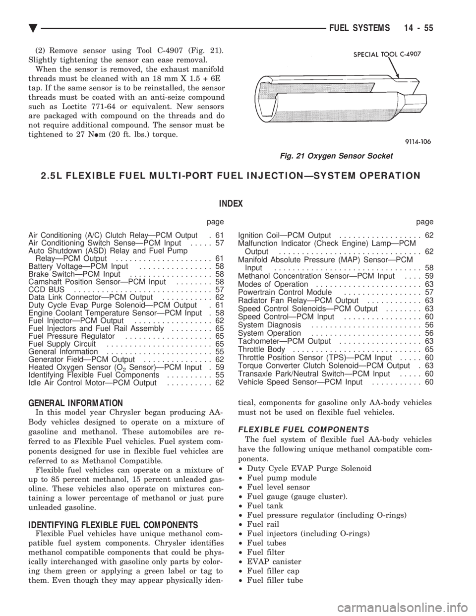
(2) Remove sensor using Tool C-4907 (Fig. 21).
Slightly tightening the sensor can ease removal. When the sensor is removed, the exhaust manifold
threads must be cleaned with an 18 mm X 1.5 + 6E
tap. If the same sensor is to be reinstalled, the sensor
threads must be coated with an anti-seize compound
such as Loctite 771-64 or equivalent. New sensors
are packaged with compound on the threads and do
not require additional compound. The sensor must be
tightened to 27 N Im (20 ft. lbs.) torque.
2.5L FLEXIBLE FUEL MULTI-PORT FUEL INJECTIONÐSYSTEM OPERATION
INDEX
page page
Air Conditioning (A/C) Clutch RelayÐPCM Output.61
Air Conditioning Switch SenseÐPCM Input ..... 57
Auto Shutdown (ASD) Relay and Fuel Pump RelayÐPCM Output ..................... 61
Battery VoltageÐPCM Input ................ 58
Brake SwitchÐPCM Input .................. 58
Camshaft Position SensorÐPCM Input ........ 58
CCD BUS .............................. 57
Data Link ConnectorÐPCM Output ........... 62
Duty Cycle Evap Purge SolenoidÐPCM Output . 61
Engine Coolant Temperature SensorÐPCM Input . 58
Fuel InjectorÐPCM Output ................. 62
Fuel Injectors and Fuel Rail Assembly ......... 65
Fuel Pressure Regulator ................... 65
Fuel Supply Circuit ....................... 65
General Information ....................... 55
Generator FieldÐPCM Output ............... 62
Heated Oxygen Sensor (O
2Sensor)ÐPCM Input . 59
Identifying Flexible Fuel Components .......... 55
Idle Air Control MotorÐPCM Output .......... 62 Ignition CoilÐPCM Output
.................. 62
Malfunction Indicator (Check Engine) LampÐPCM Output ............................... 62
Manifold Absolute Pressure (MAP) SensorÐPCM Input ................................ 58
Methanol Concentration SensorÐPCM Input .... 59
Modes of Operation ....................... 63
Powertrain Control Module ................. 57
Radiator Fan RelayÐPCM Output ............ 63
Speed Control SolenoidsÐPCM Output ........ 63
Speed ControlÐPCM Input ................. 60
System Diagnosis ........................ 56
System Operation ........................ 56
TachometerÐPCM Output .................. 63
Throttle Body ............................ 65
Throttle Position Sensor (TPS)ÐPCM Input ..... 60
Torque Converter Clutch SolenoidÐPCM Output . 63
Transaxle Park/Neutral SwitchÐPCM Input ..... 60
Vehicle Speed SensorÐPCM Input ........... 60
GENERAL INFORMATION
In this model year Chrysler began producing AA-
Body vehicles designed to operate on a mixture of
gasoline and methanol. These automobiles are re-
ferred to as Flexible Fuel vehicles. Fuel system com-
ponents designed for use in flexible fuel vehicles are
referred to as Methanol Compatible. Flexible fuel vehicles can operate on a mixture of
up to 85 percent methanol, 15 percent unleaded gas-
oline. These vehicles also operate on mixtures con-
taining a lower percentage of methanol or just pure
unleaded gasoline.
IDENTIFYING FLEXIBLE FUEL COMPONENTS
Flexible Fuel vehicles have unique methanol com-
patible fuel system components. Chrysler identifies
methanol compatible components that could be phys-
ically interchanged with gasoline only parts by color-
ing them green or applying a green label or tag to
them. Even though they may appear physically iden- tical, components for gasoline only AA-body vehicles
must not be used on flexible fuel vehicles.
FLEXIBLE FUEL COMPONENTS
The fuel system of flexible fuel AA-body vehicles
have the following unique methanol compatible com-
ponents.
² Duty Cycle EVAP Purge Solenoid
² Fuel pump module
² Fuel level sensor
² Fuel gauge (gauge cluster).
² Fuel tank
² Fuel pressure regulator (including O-rings)
² Fuel rail
² Fuel injectors (including O-rings)
² Fuel tubes
² Fuel filter
² EVAP canister
² Fuel filler cap
² Fuel filler tube
Fig. 21 Oxygen Sensor Socket
Ä FUEL SYSTEMS 14 - 55
Page 1919 of 2438
STEERING
CONTENTS
page page
ACUSTAR STANDARD AND TILT STEERING COLUMN ............................ 28
AUTOMATIC TRANSMISSION SHIFTER/IGNITION INTERLOCK .......................... 36
GENERAL INFORMATION .................. 1 POWER STEERING GEAR
................ 25
POWER STEERING PUMPS ................ 1
SPECIFICATIONS AND TIGHTENING REFERENCE .......................... 42
GENERAL INFORMATION
Safety goggles should be worn at all times
when working on any steering gear or pump. Throughout this group, references may be made to
a particular vehicle by letter or number designation.
A chart showing the breakdown of these designations
is included in the Introduction Section at the front of
this service manual. The power steering system consists of these four
major components. Power Steering Pump, Power
Steering Gear, Pressure Hose, and Return Line.
Turning of the steering wheel is converted into lin-
ear travel through the meshing of the helical pinion teeth with the rack teeth. Power assist steering is
provided by an open center, rotary type control valve.
It is used to direct oil from the power steering pump
to either side of the integral steering rack piston. Road feel is controlled by the diameter of a torsion
bar which initially steers the vehicle. As steering ef-
fort increases as in a turn, the torsion bar twists,
causing relative rotary motion between the rotary
valve body and valve spool. This movement directs
oil behind the integral rack piston, which in turn,
builds up hydraulic pressure and assists in the turn-
ing effort.
POWER STEERING PUMPS
INDEX
page page
Checking Power Steering Fluid Level .......... 9
Flow Control Valve Fitting O-Ring Seal ........ 23
General Information ........................ 1
Power Steering Hoses ..................... 11
Power Steering Pressure Switch ............. 10
Power Steering Pump Fluid Reservoirs ........ 22 Power Steering Pump Pressure Test
........... 9
Power Steering Pump Pulley Service .......... 20
Power Steering Pump Removal .............. 12
Power Steering Pump Service ................ 2
Power Steering PumpÐInitial Operation ....... 24
Steering Components Service Diagnosis ........ 2
GENERAL INFORMATION
Hydraulic pressure for operation of the power
steering gear is provided by a belt driven power
steering pump. The power steering pump is a con-
stant flow rate and displacement, vane type pump.
Different styles of Saginaw power steering pumps are
used depending on the engine application of the ve-
hicle. On all four cylinder and 3.0-liter V-6 applications
the Saginaw Ham Can power steering pump is used
(Fig. 1). On the 3.3 & 3.8-liter V-6 and Turbo III applica-
tions, different versions of the Saginaw T/C style
power steering pump is used (Fig. 2). The 3.3 & 3.8 liter V-6 engine application uses the T/C style power
steering pump with a remote mounted reservoir for
the power steering fluid. On the Turbo III application
of the T/C style power steering pump, the power
steering fluid reservoir is integral to the power steer-
ing pump. On the integral reservoir type pump (Fig. 1) the
pump housing and internal components are combined
with the reservoir to form a one-piece mechanism. The Saginaw T/C style power steering pump (Fig.
2), consists of the power steering pump internal com-
ponents and pump housing. The Saginaw T/C style
power steering pump though has no internal reser-
voir for the power steering fluid. Depending on vehi-
Ä STEERING 19 - 1