1993 CHEVROLET DYNASTY oil level
[x] Cancel search: oil levelPage 2059 of 2438
CAUTION: If the vehicle is equipped with two oil
coolers (one in the radiator tank, one in front of the
radiator) they must be flushed separately. Do not
attempt to flush both coolers at one time. (1) Disconnect the cooler lines at the transmission.
(2) Using a hand suction gun filled with mineral
spirits, reverse flush the cooler. Force mineral spirits
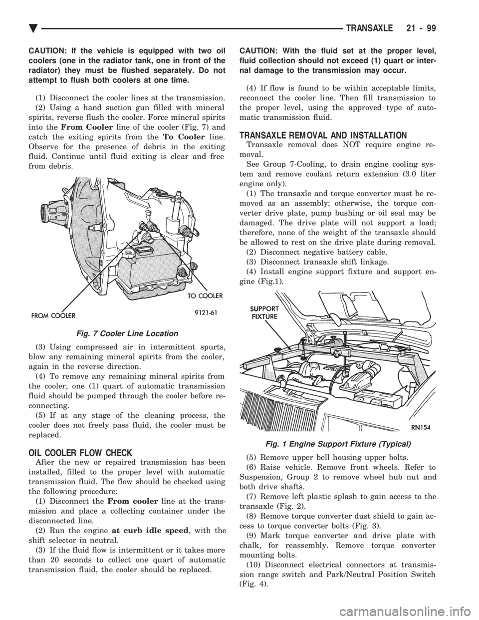
into the From Cooler line of the cooler (Fig. 7) and
catch the exiting spirits from the To Coolerline.
Observe for the presence of debris in the exiting
fluid. Continue until fluid exiting is clear and free
from debris.
(3) Using compressed air in intermittent spurts,
blow any remaining mineral spirits from the cooler,
again in the reverse direction. (4) To remove any remaining mineral spirits from
the cooler, one (1) quart of automatic transmission
fluid should be pumped through the cooler before re-
connecting. (5) If at any stage of the cleaning process, the
cooler does not freely pass fluid, the cooler must be
replaced.
OIL COOLER FLOW CHECK
After the new or repaired transmission has been
installed, filled to the proper level with automatic
transmission fluid. The flow should be checked using
the following procedure: (1) Disconnect the From coolerline at the trans-
mission and place a collecting container under the
disconnected line. (2) Run the engine at curb idle speed , with the
shift selector in neutral. (3) If the fluid flow is intermittent or it takes more
than 20 seconds to collect one quart of automatic
transmission fluid, the cooler should be replaced. CAUTION: With the fluid set at the proper level,
fluid collection should not exceed (1) quart or inter-
nal damage to the transmission may occur.
(4) If flow is found to be within acceptable limits,
reconnect the cooler line. Then fill transmission to
the proper level, using the approved type of auto-
matic transmission fluid.
TRANSAXLE REMOVAL AND INSTALLATION
Transaxle removal does NOT require engine re-
moval. See Group 7-Cooling, to drain engine cooling sys-
tem and remove coolant return extension (3.0 liter
engine only). (1) The transaxle and torque converter must be re-
moved as an assembly; otherwise, the torque con-
verter drive plate, pump bushing or oil seal may be
damaged. The drive plate will not support a load;
therefore, none of the weight of the transaxle should
be allowed to rest on the drive plate during removal. (2) Disconnect negative battery cable.
(3) Disconnect transaxle shift linkage.
(4) Install engine support fixture and support en-
gine (Fig.1).
(5) Remove upper bell housing upper bolts.
(6) Raise vehicle. Remove front wheels. Refer to
Suspension, Group 2 to remove wheel hub nut and
both drive shafts. (7) Remove left plastic splash to gain access to the
transaxle (Fig. 2). (8) Remove torque converter dust shield to gain ac-
cess to torque converter bolts (Fig. 3). (9) Mark torque converter and drive plate with
chalk, for reassembly. Remove torque converter
mounting bolts. (10) Disconnect electrical connectors at transmis-
sion range switch and Park/Neutral Position Switch
(Fig. 4).
Fig. 7 Cooler Line Location
Fig. 1 Engine Support Fixture (Typical)
Ä TRANSAXLE 21 - 99
Page 2151 of 2438
ponents. Under extremes of suspension and steering
travel tire damage may occur.
WARNING: FAILURE TO EQUIP THE VEHICLE WITH
TIRES HAVING ADEQUATE SPEED RATING CAN
CAUSE SUDDEN TIRE FAILURE.
ROTATION
DIRECTIONAL TREAD PATTERN TIRES
Some vehicles are fitted with special high-perfor-
mance tires having a directional tread pattern de-
signed to improve traction on wet pavement. To obtain the full benefits of this design, the tires
must be installed so that they rotate in the correct
direction. This is indicated by arrows on the tire
sidewalls. When wheels and tires are being installed, extra
care is needed to ensure that this direction of rota-
tion is maintained. Refer to Owner's Manual for rotation schedule.
NONDIRECTIONAL TIRES
Tires on the front and rear axles of vehicles oper-
ate at different loads and perform different steering,
driving, and braking functions. For these reasons,
they wear at unequal rates, and tend to develop ir-
regular wear patterns. These effects can be reduced
by timely rotation of tires. Rotation will increase
tread life, help to maintain mud, snow, and wet trac-
tion levels, and contribute to a smooth, quiet ride. The suggested rotation method is the forward-cross
tire rotation method. This method takes advantage of
current tire industry practice which now allows cross
rotation of radial-ply tires. Refer to the owner's man-
ual (usually found in the glove box) for additional in-
formation. Other rotation methods may be used, but
may not have all the benefits of the recommended
method. Always check air pressure and wheel nut tightness
after rotation. Do NOT use oil or grease on studs
or nuts. Refer to Owner's Manual for rotation schedule.
TREAD WEAR INDICATORS
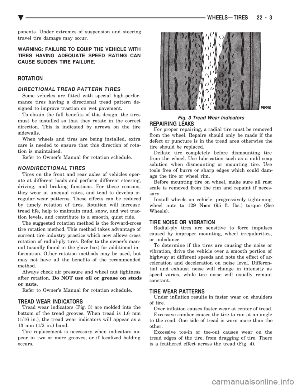
Tread wear indicators (Fig. 3) are molded into the
bottom of the tread grooves. When tread is 1.6 mm
(1/16 in.), the tread wear indicators will appear as a
13 mm (1/2 in.) band. Tire replacement is necessary when indicators ap-
pear in two or more grooves, or if localized balding
occurs.
REPAIRING LEAKS
For proper repairing, a radial tire must be removed
from the wheel. Repairs should only be made if the
defect or puncture is in the tread area otherwise the
tire should be replaced. Deflate tire completely before dismounting tire
from the wheel. Use lubrication such as a mild soap
solution when dismounting or mounting tire. Use
tools free of burrs or sharp edges which could dam-
age the tire or wheel rim. Before mounting tire on wheel, make sure all rust
scale is removed from the rim and repaint if neces-
sary. Install wheels on vehicle, progressively tightening
wheel nuts to 129 N Im (95 ft. lbs.) torque (See
Wheels).
TIRE NOISE OR VIBRATION
Radial-ply tires are sensitive to force impulses
caused by improper mounting, wheel irregularities,
or imbalance. To determine if the tires are causing the noise or
vibration, drive the vehicle over a smooth portion of
highway at different speeds and note the effect of ac-
celeration and deceleration on noise level. Differen-
tial and exhaust noise will change in intensity as
speed varies, while tire noise will usually remain
constant.
TIRE WEAR PATTERNS
Under inflation results in faster wear on shoulders
of tire. Over inflation causes faster wear at center of tread.
Excessive camber causes the tire to run at an angle
to the road. One side of tread is worn more than the
other. Excessive toe-in or toe-out causes wear on the
tread edges of the tire, from dragging of tire. There
is a feathered effect across the tread (Fig. 4).
Fig. 3 Tread Wear Indicators
Ä WHEELSÐTIRES 22 - 3
Page 2312 of 2438
REFRIGERANT SERVICE PROCEDURES INDEX
page page
Adding Partial Refrigerant Charge ............ 10
Charging Refrigerant SystemÐEmpty System . . . 11
Discharging Refrigerant System .............. 11
Evacuating Refrigerant System .............. 11
Manifold Gauge Set Connections ............. 9 Oil Level
............................... 12
R-12 Refrigerant Equipment ................. 8
Refrigerant Recycling ...................... 9
Sight Glass Refrigerant Level Inspection ........ 8
Testing for Refrigerant Leaks ............... 10
SIGHT GLASS REFRIGERANT LEVEL INSPECTION
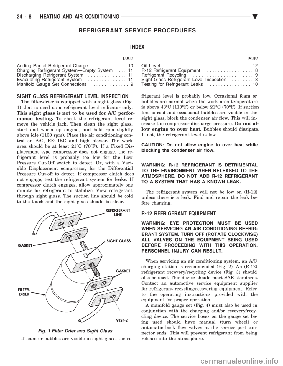
The filter-drier is equipped with a sight glass (Fig.
1) that is used as a refrigerant level indicator only.
This sight glass is not to be used for A/C perfor-
mance testing. To check the refrigerant level re-
move the vehicle jack. Then clean the sight glass,
start and warm up engine, and hold rpm slightly
above idle (1100 rpm). Place the air conditioning con-
trol on A/C, RECIRC and high blower. The work
area should be at least 21ÉC (70ÉF). If a Fixed Dis-
placement type compressor does not engage, the re-
frigerant level is probably too low for the Low
Pressure Cut-Off switch to detect. Or, with a Vari-
able Displacement compressor, for the Differential
Pressure Cut-off to detect. If compressor clutch does
not engage, test the refrigerant system for leaks. If
compressor clutch engages, allow approximately one
minute for refrigerant to stabilize. View refrigerant
through sight glass. The suction line should be cold
to the touch and the sight glass should be clear.
If foam or bubbles are visible in sight glass, the re- frigerant level is probably low. Occasional foam or
bubbles are normal when the work area temperature
is above 43ÉC (110ÉF) or below 21ÉC (70ÉF). If suction
line is cold and occasional bubbles are visible in the
sight glass, block the condenser air flow. This will in-
crease the compressor discharge pressure. Do not al-
low engine to over heat. Bubbles should dissipate.
If not, the refrigerant level is low.
CAUTION: Do not allow engine to over heat while
blocking the condenser air flow.
WARNING: R-12 REFRIGERANT IS DETRIMENTAL
TO THE ENVIRONMENT WHEN RELEASED TO THE
ATMOSPHERE. DO NOT ADD R-12 REFRIGERANT
TO A SYSTEM THAT HAS A KNOWN LEAK.
The refrigerant system will not be low on (R-12)
unless there is a leak. Find and repair the leak be-
fore charging.
R-12 REFRIGERANT EQUIPMENT
WARNING: EYE PROTECTION MUST BE USED
WHEN SERVICING AN AIR CONDITIONING REFRIG-
ERANT SYSTEM. TURN OFF (ROTATE CLOCKWISE)
ALL VALVES ON THE EQUIPMENT BEING USED
BEFORE PROCEEDING WITH THIS OPERATION.
PERSONNEL INJURY CAN RESULT.
When servicing an air conditioning system, an A/C
charging station is recommended (Fig. 2). An (R-12)
refrigerant recovery/recycling device (Fig. 3) should
also be used. This device should meet SAE standards.
Contact an automotive service equipment supplier
for refrigerant recycling/recovering equipment. Refer
to the operating instructions provided with the
equipment for proper operation. A manifold gauge set (Fig. 4) must also be used in
conjunction with the charging and/or recovery/recy-
cling device. The service hoses on the gauge set be-
ing used should have manual (turn wheel) or
automatic back flow valves at the service port con-
nector ends. This will prevent refrigerant from being
release into the atmosphere.
Fig. 1 Filter Drier and Sight Glass
24 - 8 HEATING AND AIR CONDITIONING Ä
Page 2314 of 2438
backed off, immediately point the end of hose toward
floor, as possibly trapped refrigerant in the hose will
be released.(e) Install service port cap.
DISCHARGE (HIGH PRESSURE) GAUGE CONNECTION (1) Remove the service port cap from the 1/4 in.
service port. (2) Check all valves on the equipment being used to
verify they are closed. (3) Inspect the hose gasket in the service port con-
nector at the end of the (RED) hose. If the gasket is
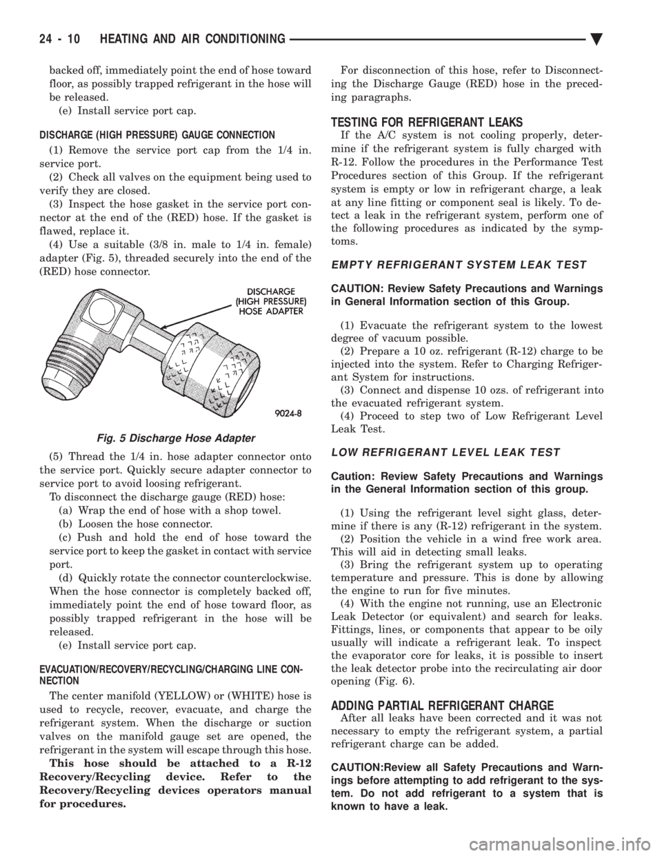
flawed, replace it. (4) Use a suitable (3/8 in. male to 1/4 in. female)
adapter (Fig. 5), threaded securely into the end of the
(RED) hose connector.
(5) Thread the 1/4 in. hose adapter connector onto
the service port. Quickly secure adapter connector to
service port to avoid loosing refrigerant. To disconnect the discharge gauge (RED) hose:(a) Wrap the end of hose with a shop towel.
(b) Loosen the hose connector.
(c) Push and hold the end of hose toward the
service port to keep the gasket in contact with service
port. (d) Quickly rotate the connector counterclockwise.
When the hose connector is completely backed off,
immediately point the end of hose toward floor, as
possibly trapped refrigerant in the hose will be
released. (e) Install service port cap.
EVACUATION/RECOVERY/RECYCLING/CHARGING LINE CON-
NECTION
The center manifold (YELLOW) or (WHITE) hose is
used to recycle, recover, evacuate, and charge the
refrigerant system. When the discharge or suction
valves on the manifold gauge set are opened, the
refrigerant in the system will escape through this hose. This hose should be attached to a R-12
Recovery/Recycling device. Refer to the
Recovery/Recycling devices operators manual
for procedures. For disconnection of this hose, refer to Disconnect-
ing the Discharge Gauge (RED) hose in the preced-
ing paragraphs.
TESTING FOR REFRIGERANT LEAKS
If the A/C system is not cooling properly, deter-
mine if the refrigerant system is fully charged with
R-12. Follow the procedures in the Performance Test
Procedures section of this Group. If the refrigerant
system is empty or low in refrigerant charge, a leak
at any line fitting or component seal is likely. To de-
tect a leak in the refrigerant system, perform one of
the following procedures as indicated by the symp-
toms.
EMPTY REFRIGERANT SYSTEM LEAK TEST
CAUTION: Review Safety Precautions and Warnings
in General Information section of this Group.
(1) Evacuate the refrigerant system to the lowest
degree of vacuum possible. (2) Prepare a 10 oz. refrigerant (R-12) charge to be
injected into the system. Refer to Charging Refriger-
ant System for instructions. (3) Connect and dispense 10 ozs. of refrigerant into
the evacuated refrigerant system. (4) Proceed to step two of Low Refrigerant Level
Leak Test.
LOW REFRIGERANT LEVEL LEAK TEST
Caution: Review Safety Precautions and Warnings
in the General Information section of this group.
(1) Using the refrigerant level sight glass, deter-
mine if there is any (R-12) refrigerant in the system. (2) Position the vehicle in a wind free work area.
This will aid in detecting small leaks. (3) Bring the refrigerant system up to operating
temperature and pressure. This is done by allowing
the engine to run for five minutes. (4) With the engine not running, use an Electronic
Leak Detector (or equivalent) and search for leaks.
Fittings, lines, or components that appear to be oily
usually will indicate a refrigerant leak. To inspect
the evaporator core for leaks, it is possible to insert
the leak detector probe into the recirculating air door
opening (Fig. 6).
ADDING PARTIAL REFRIGERANT CHARGE
After all leaks have been corrected and it was not
necessary to empty the refrigerant system, a partial
refrigerant charge can be added.
CAUTION:Review all Safety Precautions and Warn-
ings before attempting to add refrigerant to the sys-
tem. Do not add refrigerant to a system that is
known to have a leak.
Fig. 5 Discharge Hose Adapter
24 - 10 HEATING AND AIR CONDITIONING Ä
Page 2315 of 2438
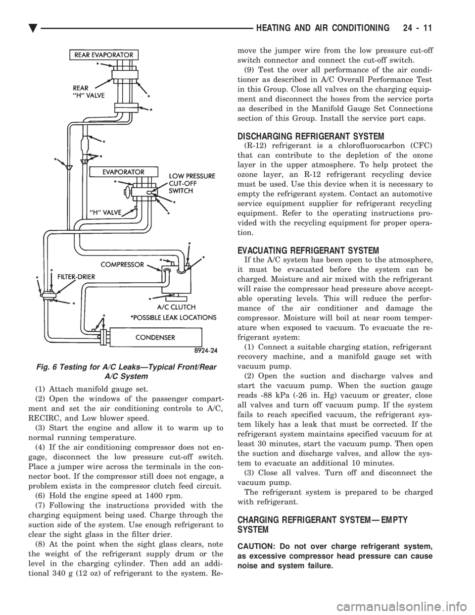
(1) Attach manifold gauge set.
(2) Open the windows of the passenger compart-
ment and set the air conditioning controls to A/C,
RECIRC, and Low blower speed. (3) Start the engine and allow it to warm up to
normal running temperature. (4) If the air conditioning compressor does not en-
gage, disconnect the low pressure cut-off switch.
Place a jumper wire across the terminals in the con-
nector boot. If the compressor still does not engage, a
problem exists in the compressor clutch feed circuit. (6) Hold the engine speed at 1400 rpm.
(7) Following the instructions provided with the
charging equipment being used. Charge through the
suction side of the system. Use enough refrigerant to
clear the sight glass in the filter drier. (8) At the point when the sight glass clears, note
the weight of the refrigerant supply drum or the
level in the charging cylinder. Then add an addi-
tional 340 g (12 oz) of refrigerant to the system. Re- move the jumper wire from the low pressure cut-off
switch connector and connect the cut-off switch.
(9) Test the over all performance of the air condi-
tioner as described in A/C Overall Performance Test
in this Group. Close all valves on the charging equip-
ment and disconnect the hoses from the service ports
as described in the Manifold Gauge Set Connections
section of this Group. Install the service port caps.
DISCHARGING REFRIGERANT SYSTEM
(R-12) refrigerant is a chlorofluorocarbon (CFC)
that can contribute to the depletion of the ozone
layer in the upper atmosphere. To help protect the
ozone layer, an R-12 refrigerant recycling device
must be used. Use this device when it is necessary to
empty the refrigerant system. Contact an automotive
service equipment supplier for refrigerant recycling
equipment. Refer to the operating instructions pro-
vided with the recycling equipment for proper opera-
tion.
EVACUATING REFRIGERANT SYSTEM
If the A/C system has been open to the atmosphere,
it must be evacuated before the system can be
charged. Moisture and air mixed with the refrigerant
will raise the compressor head pressure above accept-
able operating levels. This will reduce the perfor-
mance of the air conditioner and damage the
compressor. Moisture will boil at near room temper-
ature when exposed to vacuum. To evacuate the re-
frigerant system: (1) Connect a suitable charging station, refrigerant
recovery machine, and a manifold gauge set with
vacuum pump. (2) Open the suction and discharge valves and
start the vacuum pump. When the suction gauge
reads -88 kPa (-26 in. Hg) vacuum or greater, close
all valves and turn off vacuum pump. If the system
fails to reach specified vacuum, the refrigerant sys-
tem likely has a leak that must be corrected. If the
refrigerant system maintains specified vacuum for at
least 30 minutes, start the vacuum pump. Then open
the suction and discharge valves, and allow the sys-
tem to evacuate an additional 10 minutes. (3) Close all valves. Turn off and disconnect the
vacuum pump. The refrigerant system is prepared to be charged
with refrigerant.
CHARGING REFRIGERANT SYSTEMÐEMPTY
SYSTEM
CAUTION: Do not over charge refrigerant system,
as excessive compressor head pressure can cause
noise and system failure.
Fig. 6 Testing for A/C LeaksÐTypical Front/Rear A/C System
Ä HEATING AND AIR CONDITIONING 24 - 11
Page 2316 of 2438
WARNING: REVIEW SAFETY PRECAUTIONS AND
WARNINGS BEFORE CHARGING THE REFRIGER-
ANT SYSTEM.
After the system has been tested for leaks and
evacuated, a refrigerant charge can be injected into
the system. (1) Connect manifold gauge set.
(2) Measure refrigerant (refer to capacities) and
heat to 52ÉC (125ÉF) with the charging station. Refer
to the instructions provided with the equipment be-
ing used.
REFRIGERANT CAPACITIES:
² Without Rear A/C = 907 g (32 oz.)
² With Rear A/C = 1219 g (43 oz.)
(3) Open the suction and discharge valves. Open
the charge valve to allow the heated refrigerant to
flow into the system. When the transfer of refriger-
ant has stopped, close the suction and discharge
valve. (4) If all of the refrigerant charge did not transfer
from the dispensing device, start engine and hold at
idle (1400 rpm). Set the A/C control to A/C, low
blower speed, and open windows. If the A/C compres-
sor does not engage, test the compressor clutch con-
trol circuit and correct any failure. Refer to Group
8W, Wiring Diagrams. (5) Open the suction valve to allow the remaining
refrigerant to transfer to the system.
WARNING: TAKE CARE NOT TO OPEN THE DIS-
CHARGE (HIGH-PRESSURE) VALVE AT THIS TIME.
(6) Close all valves and test the A/C system perfor-
mance. Refer to Heater and A/C Performance Tests
in this Group. (7) Disconnect the charging station or manifold
gauge set. Install the service port caps.
OIL LEVEL
It is important to have the correct amount of oil in
the A/C system to ensure proper lubrication of the
compressor. Too little oil will result in damage to the
compressor. Too much oil will reduce the cooling ca-
pacity of the system. The oil used in the compressor is a 500 SUS viscos-
ity, wax-free refrigerant oil. Only refrigerant oil of
the same type should be used to service the system.
Do not use any other oil. The oil container should be
kept tightly capped until it is ready for use, and then
tightly capped after use to prevent contamination
from dirt and moisture. Refrigerant oil will quickly
absorb any moisture it comes in contact with. It will not be necessary to check oil level in the
compressor or to add oil unless there has been an oil
loss. This may be due to a ruptured line, shaft seal leakage, leakage from the evaporator, condenser
leak, filter drier or loss of refrigerant due to a colli-
sion. Oil loss at a the leak point will be evident by
the presence of a wet, shiny surface around the leak.
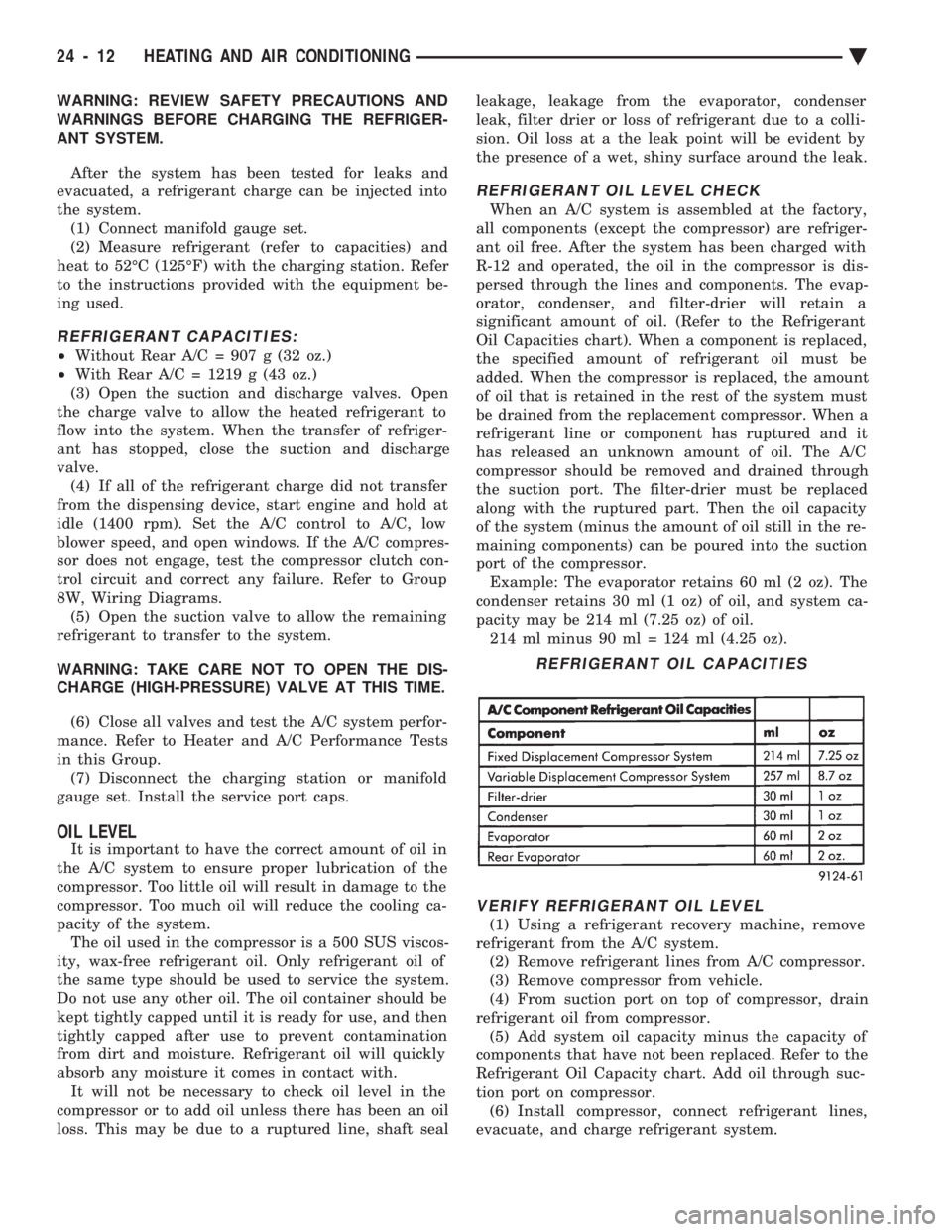
REFRIGERANT OIL LEVEL CHECK
When an A/C system is assembled at the factory,
all components (except the compressor) are refriger-
ant oil free. After the system has been charged with
R-12 and operated, the oil in the compressor is dis-
persed through the lines and components. The evap-
orator, condenser, and filter-drier will retain a
significant amount of oil. (Refer to the Refrigerant
Oil Capacities chart). When a component is replaced,
the specified amount of refrigerant oil must be
added. When the compressor is replaced, the amount
of oil that is retained in the rest of the system must
be drained from the replacement compressor. When a
refrigerant line or component has ruptured and it
has released an unknown amount of oil. The A/C
compressor should be removed and drained through
the suction port. The filter-drier must be replaced
along with the ruptured part. Then the oil capacity
of the system (minus the amount of oil still in the re-
maining components) can be poured into the suction
port of the compressor. Example: The evaporator retains 60 ml (2 oz). The
condenser retains 30 ml (1 oz) of oil, and system ca-
pacity may be 214 ml (7.25 oz) of oil. 214 ml minus 90 ml = 124 ml (4.25 oz).
VERIFY REFRIGERANT OIL LEVEL
(1) Using a refrigerant recovery machine, remove
refrigerant from the A/C system. (2) Remove refrigerant lines from A/C compressor.
(3) Remove compressor from vehicle.
(4) From suction port on top of compressor, drain
refrigerant oil from compressor. (5) Add system oil capacity minus the capacity of
components that have not been replaced. Refer to the
Refrigerant Oil Capacity chart. Add oil through suc-
tion port on compressor. (6) Install compressor, connect refrigerant lines,
evacuate, and charge refrigerant system.
REFRIGERANT OIL CAPACITIES
24 - 12 HEATING AND AIR CONDITIONING Ä
Page 2325 of 2438
(5) Evacuate and charge the refrigerant system. If
oil loss of 3 ml (1 oz) or greater is suspected, refer to
Oil Level in the Refrigerant Service Procedures sec-
tion.
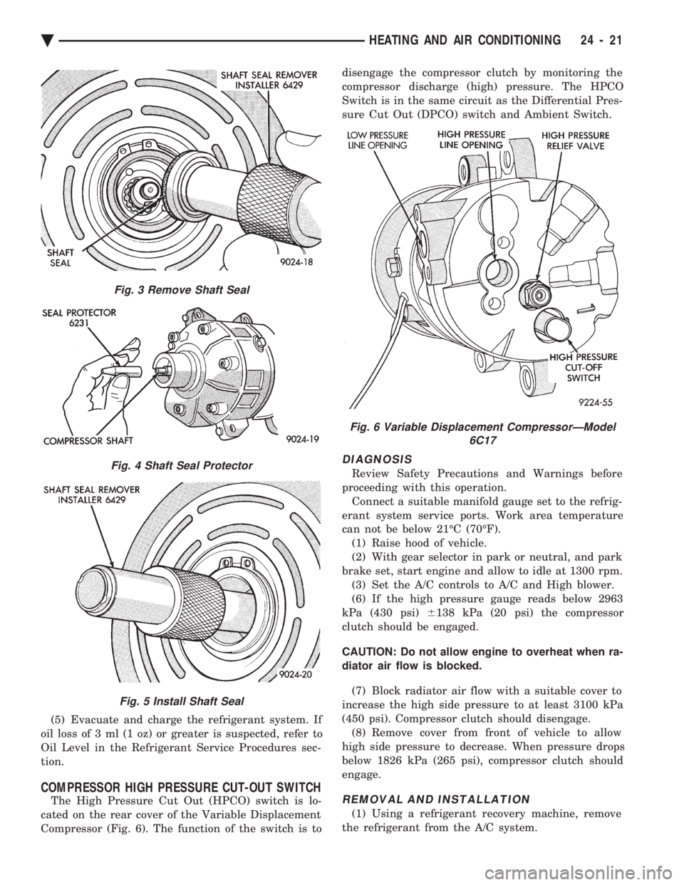
COMPRESSOR HIGH PRESSURE CUT-OUT SWITCH
The High Pressure Cut Out (HPCO) switch is lo-
cated on the rear cover of the Variable Displacement
Compressor (Fig. 6). The function of the switch is to disengage the compressor clutch by monitoring the
compressor discharge (high) pressure. The HPCO
Switch is in the same circuit as the Differential Pres-
sure Cut Out (DPCO) switch and Ambient Switch.
DIAGNOSIS
Review Safety Precautions and Warnings before
proceeding with this operation. Connect a suitable manifold gauge set to the refrig-
erant system service ports. Work area temperature
can not be below 21ÉC (70ÉF). (1) Raise hood of vehicle.
(2) With gear selector in park or neutral, and park
brake set, start engine and allow to idle at 1300 rpm. (3) Set the A/C controls to A/C and High blower.
(6) If the high pressure gauge reads below 2963
kPa (430 psi) 6138 kPa (20 psi) the compressor
clutch should be engaged.
CAUTION: Do not allow engine to overheat when ra-
diator air flow is blocked.
(7) Block radiator air flow with a suitable cover to
increase the high side pressure to at least 3100 kPa
(450 psi). Compressor clutch should disengage. (8) Remove cover from front of vehicle to allow
high side pressure to decrease. When pressure drops
below 1826 kPa (265 psi), compressor clutch should
engage.
REMOVAL AND INSTALLATION
(1) Using a refrigerant recovery machine, remove
the refrigerant from the A/C system.
Fig. 3 Remove Shaft Seal
Fig. 4 Shaft Seal Protector
Fig. 5 Install Shaft Seal
Fig. 6 Variable Displacement CompressorÐModel 6C17
Ä HEATING AND AIR CONDITIONING 24 - 21
Page 2334 of 2438
CAUTION: Refer to Oil Level in the Refrigerant Ser-
vice Procedures section for further details. (13) Install refrigeration oil (500 SUS) into the
compressor through the suction port. (14) Check compressor operation for smoothness by
rotating crankshaft at least five full revolutions. (15) Check front housing clutch coil alignment pin
for proper installation. (16) Install clutch assembly.
(17) Install compressor.
(18) Evacuate and charge refrigerant system.
COMPRESSOR HIGH-PRESSURE RELIEF VALVE
The high pressure relief valve vents only a small
amount of refrigerant necessary to reduce system
pressure and then reseats itself. The majority of the
refrigerant is conserved in the system. The valve is
calibrated to vent at a pressure of 3100 to 4140 Kpa
(450 to 600 psi). If a valve has vented a small amount of refrigerant, it does not necessarily mean
the valve is defective.
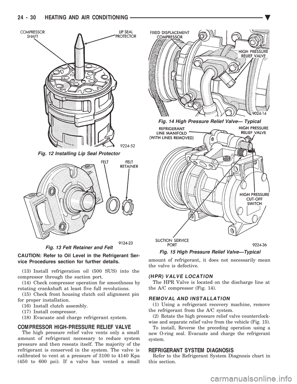
(HPR) VALVE LOCATION
The HPR Valve is located on the discharge line at
the A/C compressor (Fig. 14).
REMOVAL AND INSTALLATION
(1) Using a refrigerant recovery machine, remove
the refrigerant from the A/C system.
(2) Rotate the high pressure relief valve counterclock-
wise and separate relief valve from the vehicle (Fig. 15). To install, Reverse the preceding operation using a
new O-ring seal. Evacuate and charge the refrigerant
system.
REFRIGERANT SYSTEM DIAGNOSIS
Refer to the Refrigerant System Diagnosis chart in
this section.
Fig. 13 Felt Retainer and Felt
Fig. 14 High Pressure Relief ValveÐ Typical
Fig. 15 High Pressure Relief ValveÐTypical
Fig. 12 Installing Lip Seal Protector
24 - 30 HEATING AND AIR CONDITIONING Ä