1993 CHEVROLET DYNASTY air condition
[x] Cancel search: air conditionPage 308 of 2438
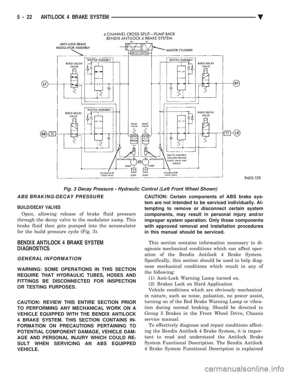
ABS BRAKING-DECAY PRESSURE
BUILD/DECAY VALVES Open, allowing release of brake fluid pressure
through the decay valve to the modulator sump. This
brake fluid then gets pumped into the accumulator
for the build pressure cycle (Fig. 3).
BENDIX ANTILOCK 4 BRAKE SYSTEM
DIAGNOSTICS
GENERAL INFORMATION
WARNING: SOME OPERATIONS IN THIS SECTION
REQUIRE THAT HYDRAULIC TUBES, HOSES AND
FITTINGS BE DISCONNECTED FOR INSPECTION
OR TESTING PURPOSES.
CAUTION: REVIEW THIS ENTIRE SECTION PRIOR
TO PERFORMING ANY MECHANICAL WORK ON A
VEHICLE EQUIPPED WITH THE BENDIX ANTILOCK
4 BRAKE SYSTEM. THIS SECTION CONTAINS IN-
FORMATION ON PRECAUTIONS PERTAINING TO
POTENTIAL COMPONENT DAMAGE, VEHICLE DAM-
AGE AND PERSONAL INJURY WHICH COULD RE-
SULT WHEN SERVICING AN ABS EQUIPPED
VEHICLE. CAUTION: Certain components of ABS brake sys-
tem are not intended to be serviced individually. At-
tempting to remove or disconnect certain system
components, may result in personal injury and/or
improper system operation. Only those components
with approved removal and installation procedures
in this manual should be serviced.
This section contains information necessary to di-
agnosis mechanical conditions which can affect oper-
ation of the Bendix Antilock 4 Brake System.
Specifically, this section should be used to help diag-
nose mechanical conditions which result in any of
the following: (1) Anti-Lock Warning Lamp turned on.
(2) Brakes Lock on Hard Application
Vehicle conditions which are obviously mechanical
in nature, such as noise, pulsation, no power assist,
turning on of the Red Brake Warning Lamp or vibra-
tion during normal braking. Should be directed to
Group 5 Brakes in the Front Wheel Drive, Chassis
service manual. To effectively diagnose and repair conditions affect-
ing the Bendix Antilock 4 Brake System, it is impor-
tant to read and understand the Antilock Brake
System Functional Description. The Bendix Antilock
4 Brake System Functional Description is explained
Fig. 3 Decay Pressure - Hydraulic Control (Left Front Wheel Shown)
5 - 22 ANTILOCK 4 BRAKE SYSTEM Ä
Page 311 of 2438
LATCHING VERSUS NON-LATCHING ABS FAULTS
Some faults detected by the CAB are latching; the
fault is latched and ABS is disabled until the igni-
tion switch is reset. Thus ABS is disabled even if the
original fault has disappeared. Other faults are non-
latching; any warning lights that are turned on, are
only turned on as long as the fault condition exists.
As soon as the condition goes away, the Antilock
Warning Light is turned off. Although a fault code
will be set in most cases.
BENDIX ANTILOCK 4 BRAKE SYSTEM DIAGNOSTICS
Bendix Antilock 4 Brake System Diagnostics, be-
yond basic mechanical diagnostics, covered earlier in
this section, are accomplished by using the DRB scan
tool. See testing procedures outlined in the 1994 Ben-
dix Antilock 4 Diagnostics Manual. Please refer to the above mentioned manual for
any further electronic diagnostics and service proce-
dures that are required on the Bendix Antilock 4
Brake System.
ON-CAR ABS BRAKE SYSTEM SERVICE
GENERAL SERVICE PRECAUTIONS
The following are general cautions which should be
observed when servicing the Bendix Antilock 4
Brake System and other vehicle electronic systems.
Failure to observe these precautions may result in
Antilock Brake System component damage. If welding work is to be performed on a vehicle us-
ing an electric arc welder, disconnect the 60 way wir-
ing harness connector from the CAB, prior to
performing the welding operation. The wiring harness connector should never be con-
nected or disconnected from the CAB with the igni-
tion key in the ON or Run position. (3) Most components making up the assemblies of
the Bendix Antilock 4 Brake System can not be ser-
viced separately from those assemblies. This will re-
quire replacement of the complete assembly for the
servicing of these components. Do not disassemble
any component from an assembly which is desig-
nated as non-serviceable.
CHECKING BRAKE FLUID LEVEL
CAUTION: Only use brake fluid conforming to DOT
3 specifications, such as Mopar or Equivalent. Do
not use any fluid which contains a petroleum base.
Do not use a container which has been used for pe-
troleum based fluids or a container which is wet
with water. Petroleum based fluids will cause swell-
ing and distortion of rubber parts in the hydraulic
brake system. Water will mix with brake fluid, low-
ering the boiling point of the brake fluid, possibly causing brake fluid to boil resulting in brake fade.
Keep all brake fluid containers capped to prevent
contamination. Remove the front cap of the master
cylinder reservoir and fill to the bottom of the split
ring.
For the specific procedure for the inspection of
brake fluid level and adding of brake to the reser-
voir. Refer to the Service Adjustments Section in this
group of the service manual.
BLEEDING BENDIX ANTILOCK 4 BRAKE SYSTEM
The base brakes and Antilock Brake System must
be bled anytime air is permitted to enter the hydrau-
lic system, due to disconnection of brake lines, hoses
or components. If the Antilock Modulator Assembly is removed
from the vehicle, both the Base Brake System and
the Antilock Brake System must be bled using the
appropriate procedure. It is important to note that
excessive air in the brake system will cause a soft or
spongy feeling brake pedal. During brake bleeding operations, ensure that
brake fluid level remains close to the FULL level in
the reservoir. Check brake fluid level periodically
during bleeding procedure, adding DOT 3 brake fluid
as required.
CAUTION: The base brake and Antilock brake hy-
draulic systems, on the Bendix Antilock 4 Brake
System, can NOT be bled using any type of brake
pressure bleeding equipment. This type of bleeding
equipment does not develop the pressure required
in the brake hydraulic system, to adequately bleed
all trapped air. The only approved method for bleed-
ing air out of the hydraulic system on vehicles
equipped with the Bendix Antilock 4 Brake System,
is the manual procedure of pressurizing the hydrau-
lic system using constant, moderate to heavy foot
pressure on the brake pedal.
The Bendix Antilock 4 Brake System must be bled
as two independent brake systems. The non ABS por-
tion of the brake system is to be bled the same as
any non ABS system. Refer to the Service Adjust-
ments section in this manual for the proper bleeding
procedure to be used. The Bendix Antilock 4 Brake
System can only be bled using a manual method of
pressurizing the brakes hydraulic system. The Antilock portion of brake system MUST be
bled separately. This bleeding procedure requires the
use of the DRB Diagnostic tester and the bleeding se-
quence procedure outlined below.
Ä ANTILOCK 4 BRAKE SYSTEM 5 - 25
Page 343 of 2438
COOLING SYSTEM
CONTENTS
page page
ACCESSORY DRIVE BELTS ............... 24
ENGINE BLOCK HEATER ................. 28
GENERAL INFORMATION .................. 1 SERVICE PROCEDURES
.................. 10
SPECIFICATIONS ....................... 29
GENERAL INFORMATION
Throughout this group, references may be made to
a particular vehicle by letter or number designation.
A chart showing the breakdown of these designations
is included in the Introduction Section at the front of
this service manual.
COOLING SYSTEM
The cooling system consists of an engine cooling
module, thermostat, coolant, a water pump to circu-
late the coolant. The engine cooling module may con-
sist of a radiator, electric fan motor, shroud, radiator
pressure cap, coolant reserve system, transmission oil
cooler, hoses, clamps, air condition condenser, trans-
mission oil lines and charge air cooler.
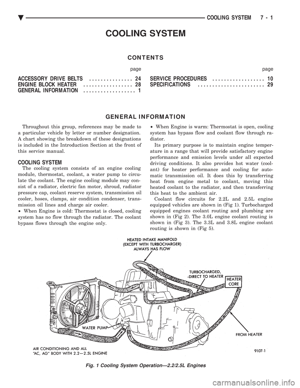
² When Engine is cold: Thermostat is closed, cooling
system has no flow through the radiator. The coolant
bypass flows through the engine only. ²
When Engine is warm: Thermostat is open, cooling
system has bypass flow and coolant flow through ra-
diator. Its primary purpose is to maintain engine temper-
ature in a range that will provide satisfactory engine
performance and emission levels under all expected
driving conditions. It also provides hot water (cool-
ant) for heater performance and cooling for auto-
matic transmission oil. It does this by transferring
heat from engine metal to coolant, moving this
heated coolant to the radiator, and then transferring
this heat to the ambient air. Coolant flow circuits for 2.2L and 2.5L engine
equipped vehicles are shown in (Fig 1). Turbocharged
equipped engines coolant routing and plumbing are
shown in (Fig 2). The 3.0L engine coolant routing is
shown in (Fig 3). The 3.3L and 3.8L engine coolant
routing is shown in (Fig 5).
Fig. 1 Cooling System OperationÐ2.2/2.5L Engines
Ä COOLING SYSTEM 7 - 1
Page 352 of 2438
SERVICE PROCEDURES INDEX
page page
Automatic Transmission Oil Coolers .......... 23
Coolant ................................ 14
Coolant Recovery System (CRS) ............. 17
Cooling System Drain, Clean, Flush and Refill . . 15
Electric Fan Motor ........................ 22
Engine Thermostats ....................... 13
Fan Shroud ............................. 23 Fans
.................................. 21
Radiator Hoses .......................... 21
Radiator Pressure Cap .................... 18
Radiators ............................... 18
Testing System for Leaks .................. 17
Water Pumps ........................... 10
WATER PUMPS
A quick test to tell whether or not the pump is
working is to see if the heater warms properly. A
defective pump will not be able to circulate heated
coolant through the long heater hose. The water pump on all models can be replaced
without discharging the air conditioning system.
WATER PUMPÐ2.2/2.5L ENGINE
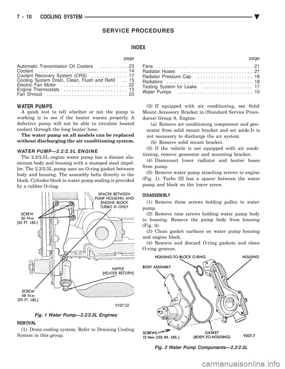
The 2.2/2.5L engine water pump has a diecast alu-
minum body and housing with a stamped steel impel-
ler. The 2.2/2.5L pump uses an O-ring gasket between
body and housing. The assembly bolts directly to the
block. Cylinder block to water pump sealing is provided
by a rubber O-ring.
REMOVAL (1) Drain cooling system. Refer to Draining Cooling
System in this group. (2) If equipped with air conditioning, see Solid
Mount Accessory Bracket in (Standard Service Proce-
dures) Group 9, Engine: (a) Remove air conditioning compressor and gen-
erator from solid mount bracket and set aside.It is
not necessary to discharge the a/c system. (b) Remove solid mount bracket.
(3) If the vehicle is not equipped with air condi-
tioning, remove generator and mounting bracket. (4) Disconnect lower radiator and heater hoses
from pump. (5) Remove water pump attaching screws to engine
(Fig. 1). Turbo III has a spacer between the water
pump and block on the lower screw.
DISASSEMBLY (1) Remove three screws holding pulley to water
pump. (2) Remove nine screws holding water pump body
to housing. Remove the pump body from housing
(Fig. 2). (3) Clean gasket surfaces on water pump housing
and engine block. (4) Remove and discard O-ring gaskets and clean
O-ring grooves.
Fig. 2 Water Pump ComponentsÐ2.2/2.5L
Fig. 1 Water PumpÐ2.2/2.5L Engines
7 - 10 COOLING SYSTEM Ä
Page 353 of 2438
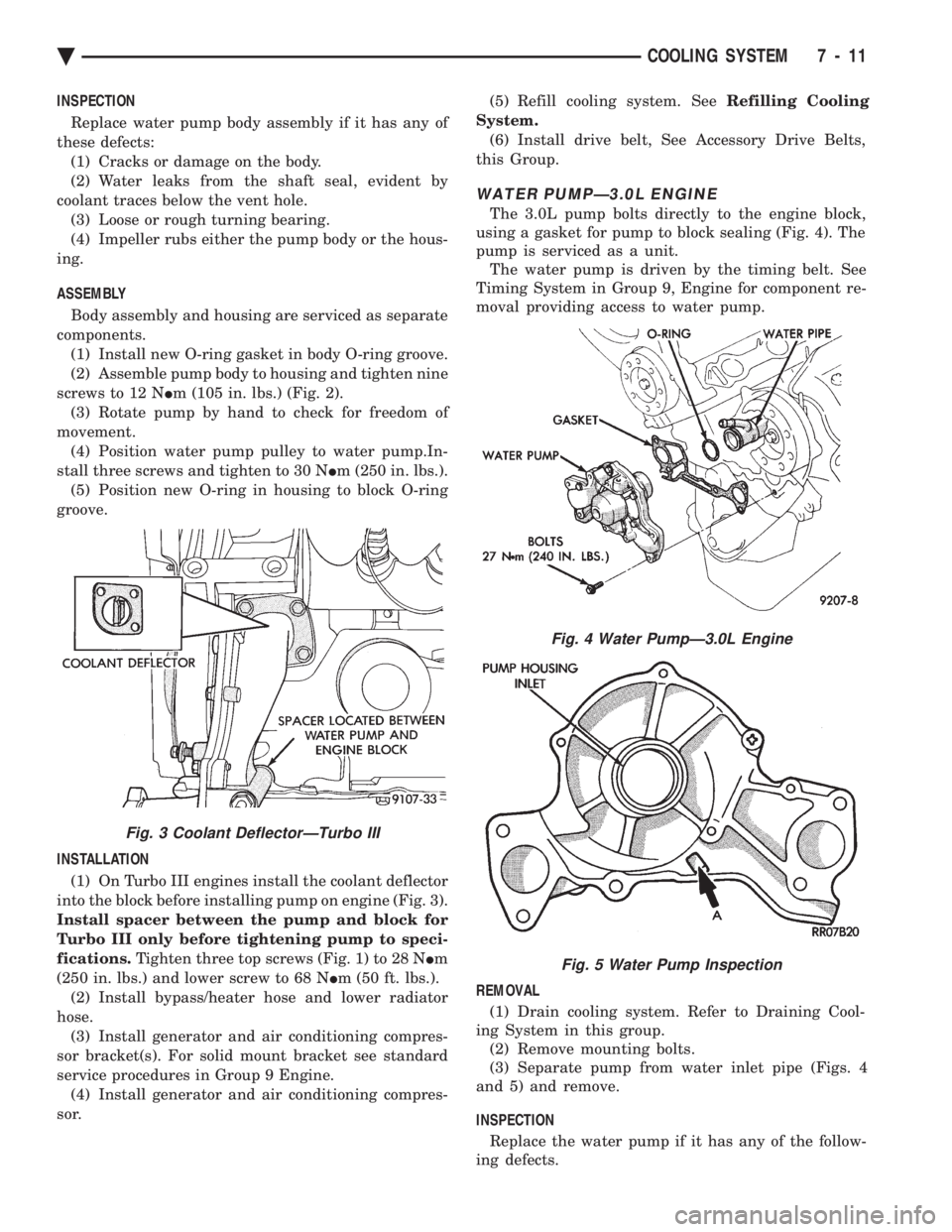
INSPECTION Replace water pump body assembly if it has any of
these defects: (1) Cracks or damage on the body.
(2) Water leaks from the shaft seal, evident by
coolant traces below the vent hole. (3) Loose or rough turning bearing.
(4) Impeller rubs either the pump body or the hous-
ing.
ASSEMBLY
Body assembly and housing are serviced as separate
components. (1) Install new O-ring gasket in body O-ring groove.
(2) Assemble pump body to housing and tighten nine
screws to 12 N Im (105 in. lbs.) (Fig. 2).
(3) Rotate pump by hand to check for freedom of
movement. (4) Position water pump pulley to water pump.In-
stall three screws and tighten to 30 N Im (250 in. lbs.).
(5) Position new O-ring in housing to block O-ring
groove.
INSTALLATION (1) On Turbo III engines install the coolant deflector
into the block before installing pump on engine (Fig. 3).
Install spacer between the pump and block for
Turbo III only before tightening pump to speci-
fications. Tighten three top screws (Fig. 1) to 28 N Im
(250 in. lbs.) and lower screw to 68 N Im (50 ft. lbs.).
(2) Install bypass/heater hose and lower radiator
hose. (3) Install generator and air conditioning compres-
sor bracket(s). For solid mount bracket see standard
service procedures in Group 9 Engine. (4) Install generator and air conditioning compres-
sor. (5) Refill cooling system. See
Refilling Cooling
System. (6) Install drive belt, See Accessory Drive Belts,
this Group.
WATER PUMPÐ3.0L ENGINE
The 3.0L pump bolts directly to the engine block,
using a gasket for pump to block sealing (Fig. 4). The
pump is serviced as a unit. The water pump is driven by the timing belt. See
Timing System in Group 9, Engine for component re-
moval providing access to water pump.
REMOVAL (1) Drain cooling system. Refer to Draining Cool-
ing System in this group. (2) Remove mounting bolts.
(3) Separate pump from water inlet pipe (Figs. 4
and 5) and remove.
INSPECTION Replace the water pump if it has any of the follow-
ing defects.
Fig. 4 Water PumpÐ3.0L Engine
Fig. 5 Water Pump Inspection
Fig. 3 Coolant DeflectorÐTurbo III
Ä COOLING SYSTEM 7 - 11
Page 355 of 2438
(5) Install drive belt. See Accessory Drive Belts
this group. (6) Install right front lower fender shield.
(7) Refill Cooling System. See Refilling Cooling
System in this section.
ENGINE THERMOSTATS
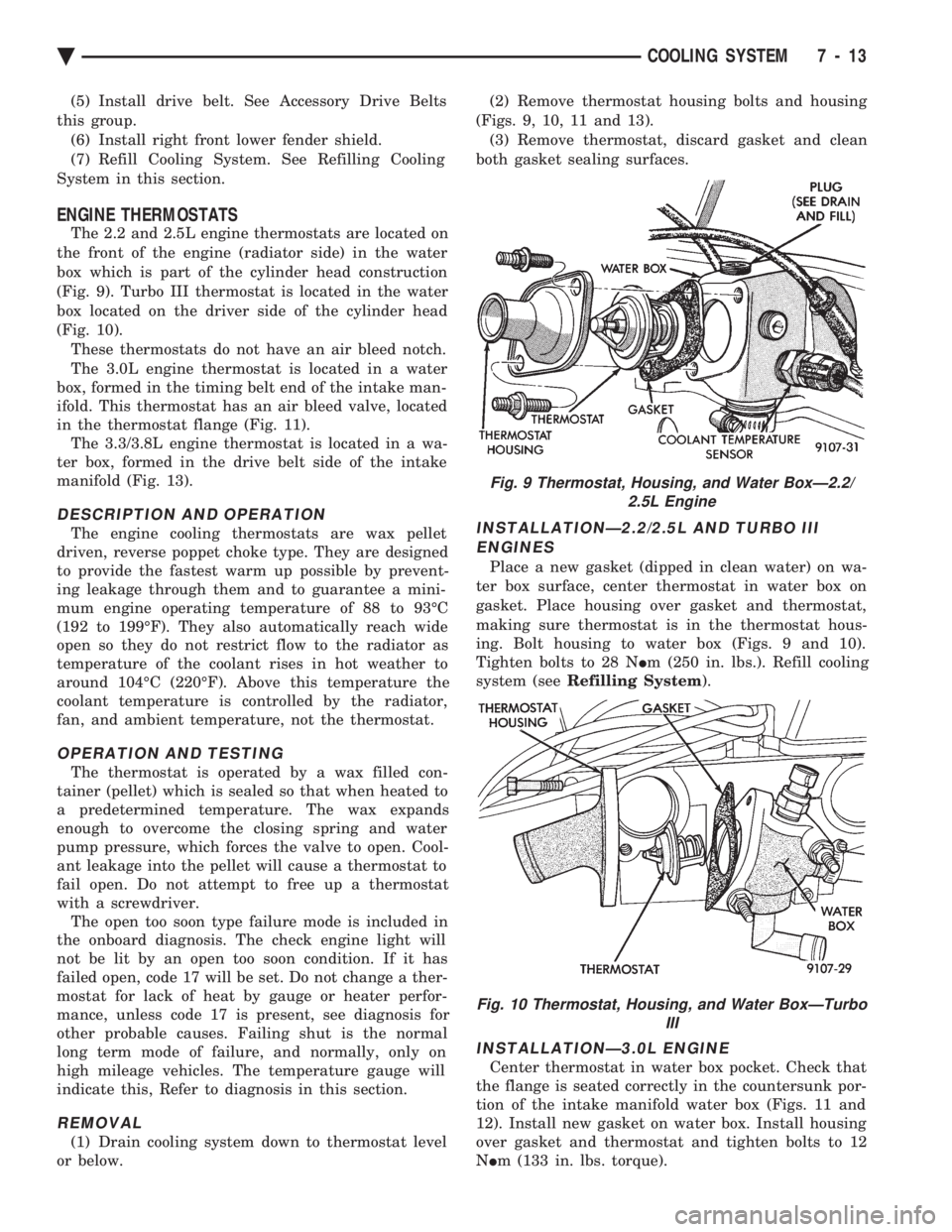
The 2.2 and 2.5L engine thermostats are located on
the front of the engine (radiator side) in the water
box which is part of the cylinder head construction
(Fig. 9). Turbo III thermostat is located in the water
box located on the driver side of the cylinder head
(Fig. 10). These thermostats do not have an air bleed notch.
The 3.0L engine thermostat is located in a water
box, formed in the timing belt end of the intake man-
ifold. This thermostat has an air bleed valve, located
in the thermostat flange (Fig. 11). The 3.3/3.8L engine thermostat is located in a wa-
ter box, formed in the drive belt side of the intake
manifold (Fig. 13).
DESCRIPTION AND OPERATION
The engine cooling thermostats are wax pellet
driven, reverse poppet choke type. They are designed
to provide the fastest warm up possible by prevent-
ing leakage through them and to guarantee a mini-
mum engine operating temperature of 88 to 93ÉC
(192 to 199ÉF). They also automatically reach wide
open so they do not restrict flow to the radiator as
temperature of the coolant rises in hot weather to
around 104ÉC (220ÉF). Above this temperature the
coolant temperature is controlled by the radiator,
fan, and ambient temperature, not the thermostat.
OPERATION AND TESTING
The thermostat is operated by a wax filled con-
tainer (pellet) which is sealed so that when heated to
a predetermined temperature. The wax expands
enough to overcome the closing spring and water
pump pressure, which forces the valve to open. Cool-
ant leakage into the pellet will cause a thermostat to
fail open. Do not attempt to free up a thermostat
with a screwdriver. The open too soon type failure mode is included in
the onboard diagnosis. The check engine light will
not be lit by an open too soon condition. If it has
failed open, code 17 will be set. Do not change a ther-
mostat for lack of heat by gauge or heater perfor-
mance, unless code 17 is present, see diagnosis for
other probable causes. Failing shut is the normal
long term mode of failure, and normally, only on
high mileage vehicles. The temperature gauge will
indicate this, Refer to diagnosis in this section.
REMOVAL
(1) Drain cooling system down to thermostat level
or below. (2) Remove thermostat housing bolts and housing
(Figs. 9, 10, 11 and 13). (3) Remove thermostat, discard gasket and clean
both gasket sealing surfaces.
INSTALLATIONÐ2.2/2.5L AND TURBO III ENGINES
Place a new gasket (dipped in clean water) on wa-
ter box surface, center thermostat in water box on
gasket. Place housing over gasket and thermostat,
making sure thermostat is in the thermostat hous-
ing. Bolt housing to water box (Figs. 9 and 10).
Tighten bolts to 28 N Im (250 in. lbs.). Refill cooling
system (see Refilling System ).
INSTALLATIONÐ3.0L ENGINE
Center thermostat in water box pocket. Check that
the flange is seated correctly in the countersunk por-
tion of the intake manifold water box (Figs. 11 and
12). Install new gasket on water box. Install housing
over gasket and thermostat and tighten bolts to 12
N Im (133 in. lbs. torque).
Fig. 9 Thermostat, Housing, and Water BoxÐ2.2/
2.5L Engine
Fig. 10 Thermostat, Housing, and Water BoxÐTurbo III
Ä COOLING SYSTEM 7 - 13
Page 362 of 2438

(2) Remove radiator pressure cap when engine is
cold, Idle engine until thermostat opens, you should
observe coolant flow while looking down the filler
neck. Once flow is detected install radiator pressure
cap.
RADIATOR
REMOVAL
(1) Disconnect negative battery cable from battery.
WARNING: DO NOT REMOVE THE CYLINDER
BLOCK PLUG OR THE RADIATOR DRAINCOCK
WITH THE SYSTEM HOT AND UNDER PRESSURE
BECAUSE SERIOUS BURNS FROM COOLANT CAN
OCCUR.
(2) Drain cooling system. Refer to Draining Cool-
ing System of this section. (3) Remove hose clamps and hoses from the radia-
tor (Fig. 11). Remove coolant reserve system tank to
filler neck tube. (4) Remove automatic transmission hoses, if
equipped. (5) Remove fan and fan support assembly by dis-
connecting fan motor electrical connector. Remove
fan shroud retaining clips, located on the top and
bottom of the shroud for AA, AG, AJ and AP vehi-
cles. AC/AY vehicle retainer clips are located on the
top only. Lift shroud up and out of bottom shroud at-
tachment clips separating shroud from radiator. Fan
damage should always be avoided. (6) Remove upper radiator mounting screws. Dis-
connect the engine block heater wire if equipped. (7) Remove the air conditioning condenser attaching
screws located at the top front of the radiator,if
equipped. Radiator can now be lifted free from engine compart-
ment. Care should be taken not to damage radia-
tor cooling fins or water tubes during removal.
INSTALLATION
(1) Slide radiator down into position behind radiator
support (yoke). (2) Attach air conditioning condenser to radiator, if
equipped, with a force of approximately 10 lbs. to seat
the radiator assembly lower rubber isolators in the
mount holes provided. (3) Tighten radiator mounting screws to 11.9N Im
(105 in. lbs.). (4) Connect automatic transmission hoses, if
equipped. Tighten hose clamps to 4 N Im (35 in. lbs.).
(5) Slide fan shroud, fan and motor down into clips
on lower radiator flange. Replace shroud retaining
clips. (6) Install upper and lower radiator hoses (including
coolant reserve hose). (7) Connect fan motor electrical connection and con-
nect negative battery cable. (8) Fill cooling system with coolant. Refer to Refill-
ing Cooling Systems. in this group.
(9) Operate engine until it reaches normal operating
temperature. Check cooling system and automatic
transmission for correct fluid levels.
Fig. 11 Cooling ModulesÐAll Models
7 - 20 COOLING SYSTEM Ä
Page 363 of 2438

RADIATOR HOSES
The hoses are removed using Constant Tension
Clamp pliers to compress hose clamp. A hardened, cracked, swollen or restricted hose
should be replaced. Do not damage radiator inlet and
outlet when loosening hoses. Radiator hoses should be routed without any kinks
and indexed as designed. The use of molded hoses is
recommended. Spring type hose clamps are used in all applica-
tions. If replacement is necessary replace with the
original style spring type clamp.
FANS
All models use electric motor driven cooling system
fans. The fan modules include a motor support which
may (depending on model) include a shroud. The
module is fastened to the radiator by screws with
U-nuts and retaining clips (Fig. 12). All fan motors are one speed. Attempts to reduce
high temperature gauge reading by increasing en-
gine speed, at the same vehicle speed, can increase
high temperature.
SINGLE FAN
There are no repairs to be made to the fan. If the
fan is warped, cracked, or otherwise damaged, it must be replaced with
onlythe recommended part for
adequate strength, performance and safety (Fig. 13).
DUAL FAN MODULEÐAC/AY BODY
The dual fan module (Fig. 11) is a combination of 2
fans mounted in a one piece shroud which are simul-
taneously activated. The dual fan system improves
engine cooling and air conditioning performance in hot
weather and severe driving conditions, while reducing
fan noise and power consumption.
REMOVAL
Disconnect electric motor lead. Remove fan module
to radiator fasteners and retaining clips. Remove as-
sembly from radiator support. To remove fan from motor shaft, bench support the
motor and motor shaft, while removing the fan retain-
ing clip, so that the shaft and motor will not be
damaged by excessive force. Surface or burr re-
moval may be required to remove fan from motor
shaft. (Fig. 13). Do not permit the fan blades to touch
the bench.
INSTALLATION
Slide the fan on motor shaft. Support motor and
shaft as above while installing fan retaining clip.
Install assembly into pocket on lower radiator tank.
Attach retaining clips and fasteners to radiator tank.
Right side fastener is longer on A/C equipped
vehicles . Connect fan motor lead. For wiring dia-
grams of fan motor systems see Wiring Diagrams
Manual
RADIATOR FAN CONTROLÐALL EXCEPT V-6 ENGINE
Fan control is accomplished two ways. The fan al-
ways runs when the air conditioning compressor
clutch is engaged. In addition to this control, the fan is
turned on by the temperature of the coolant which is
sensed by the coolant temperature sensor which
Fig. 12 Servicing Fan Module
Fig. 13 Radiator Fan Retaining ClipÐTypical
Ä COOLING SYSTEM 7 - 21