1993 CHEVROLET DYNASTY sensor
[x] Cancel search: sensorPage 1286 of 2438
Wiring Diagram
Name Sheet Number
Fuel Gauge ............................. .107
Fuel Pump Module ........................ .107
Fuel Pump Relay .......................... .108
Fuel Tank Gauge Level Sending System ............107
Fuse Application Chart (Engine Compartment) ......1,2,3,4
Fuse Application Chart (Instrument Panel) .........5,6,7,8
Fuse Block ............................... .143
Fuses Fuse 1 ...........................8,42,90,93
Fuse 5 ....................8,13,14,39,42,84,96
Fuse 6 ..............................8,42,56
Fuse 7 .............................8,42,105
Fuse 8 ................................5,52
Fuse 9 ................................5,55
Fuse 10 ..........................5,10,12,54
Fuse 11 ..........................5,60,84,88
Fuse 12 ...............................5,63
Fuse 14 .....................7,42,70,73,77,84
Fuse 15 ..........................7,42,59,70
Fuse 17 .........................6,53, 133, 137
Fuse 18 .........................6,53, 133, 137
Fuse 19 ...............................6,54
Fuse 20 ...............................6,54
Fuse 21 ..........................5,10,12,59
Fuse 22 ...............................5,65
Fuse 25 .......................8,94,95,98,100
Fuse 26 ..............8,16,73,77,94, 121, 123, 125
Fuse 27 ..........................7,42,61,63
Fuse 28 .............................7,42,67
Fuse 36 ...........................1,9,11,56
Fuse 37 ..................................1
Fuse 40 ..............................2,9,11
Fuse 41 ..............................2,9,11
Fuse 42 ...........................2,9,11,18
Fuse 43 ..................................2
Fuse 44 .............................2,10,12
Fuse 45 .............................2,10,12
Fuse 46 ..............................2,9,11
Fuse 47 ..............................2,9,11
Fuse 48 .............................1,10,12
Fuse 50 .............................1,10,12
Fuse 51 .............................2,10,12
Fuse 52 .............................4,10,12
Fuse 53 .............................4,10,12
Fuse 55 ..........................2,10,12,13
Fuse 56 ........................3,10,12,54,84
Fuse 57 ..........................3,10,12,54
Fuse 58 .............................1,10,12
Generator .............................. .10, 12
Glove Box Lamp Switch ................... .101, 103
Headlamp Switch ......................... .51, 55
Headlamp Switch System .................. .53, 54, 55
Battery ..................................53
Fog Lamp Relay ............................55
Fog Lamp Switch ...........................55
Headlamp Switch ...........................55
High Beam Relay ...........................53Wiring Diagram
Name Sheet Number
Left Pod Light .............................55
Low Beam Relay ............................53
Optical Horn Switch .........................55
Park Lamp Relay ...........................53
Parking Switch .............................55
Turn Signal Switch ..........................55
Heated Oxygen Sensor ................... .17, 24, 32
Heated Rear Window ......................8,94,95
Heated Rear Window Switch .................8,94,95
Heater System ...............................93
Blower Motor ..............................93
Blower Motor Resistor ........................93
Blower Switch .............................93
Illumination Lamp Switch ......................93
High Beam Relay ...........................6,53
Horn System ...............................65
Clockspring ...............................65
Horn Relay ...............................65
Horn Switch ..............................65
Left Horn (Lo-Note) ..........................65
Right Horn (Hi-Note) .........................65
Idle Air Control Motor ...................... .17, 23
Ignition Coil ............................. .19, 23
Ignition Switch ...........................2,7,42
Instrument Panel Fuse Application Chart ..........5,6,7,8
Intermittent Wiper System .................... .66, 67
Intermittent Windshield Wiper Motor ...............67
Park Switch ...............................67
Washer Relay .............................66
Windshield Washer Low Fluid Level Sensor ...........67
Windshield Washer Pump Motor .................67
Wiper Switch ..............................66
Interface Grommet ............................85
Key Disarm Switch ....................... .115, 116
Lamp Outage Module Connectors ..................174
Lamps A/C Heater Control Lamp ......................52
Ash Receiver Lamp ..........................51
Back-Up Lamps ...........128, 131, 133, 134, 137, 138
Cargo Lamp ............................. .126
Center High Mounted Stop Lamp ..........140, 141, 142
Cluster Lamps .............................52
Console Switch Module Lamp ...................51
Courtesy Lamps ................ .121, 122, 123, 124
Dome Lamp ......................... .118, 126
Dummy Lamp .......................... .45, 46
Fog Lamp-Left ......................... .43, 47
Fog Lamp-Right ........................ .44, 48
Glove Box Lamp ............. .101, 103, 121, 123, 125
Halo Light ....................... .121, 123, 125
Headlamp, High Beam .......43, 44, 45, 46, 47, 48, 49, 50
Headlamp, Low Beam .......43, 44, 45, 46, 47, 48, 49, 50
Illumination Lamp ....................... .90, 93
Left Pod Lamps ......................... .51, 55
License Lamp .................. .128, 131, 133, 137
Park and Turn Signal Lamp-Left ........43, 45, 47, 49, 50
Park and Turn Signal Lamp-Right .......44, 46, 48, 49, 50
8W - 536 WIRING DIAGRAMS AG-AJ BODY Ä
Page 1287 of 2438
Wiring Diagram
Name Sheet Number
Reading Lamps ....................... .124, 126
Side Marker Lamp-Left .........45, 49, 50, 128, 132, 136
Side Marker Lamp-Right ........46, 49, 50, 131, 135, 139
Stop Lamp .......... .59, 128, 131, 132, 135, 136, 139
Tail Lamps .......128, 131, 132, 134, 135, 136, 138, 139
Trunk Lamp .......................... .122, 124
Transmission Range Lamp .....................51
Turn Lamp .................... .132, 135, 136, 139
Turn Signal Lamp-Left ...................... .128
Turn Signal Lamp-Right ..................... .131
Vanity Mirror Lamp ............118, 120, 122, 124, 126
Underhood Lamp ...........................16
Left Bucket Power Seat System ...................113
Power Seat Switch ........................ .113
Left Instrument Panel to Body Wiring ...............144
Left Instrument Panel to Body Wiring with Lamp Outage . . .145
Left Instrument Panel to Body Wiring without Lamp Outage ........................ .146
Liftgate Wiper and Washer System ..............105, 106
Logic Function and Timer .................... .105
Module ................................ .105
Washer Motor ........................... .106
Wiper Motor ............................ .106
Low Beam Relay ...........................6,53
Lumbar Pump ............................. .114
Lumbar Switch ............................ .114
MAP Sensor .......................... .18, 29, 30
Mechanical Cluster #1 Left PCB Connector ............155
Mechanical Cluster #1 ...................... .73, 74
Mechanical Cluster #2 ...................... .75, 76
Mechanical Cluster #2 Right PCB Connector ...........156
Message Center ..............................88
Mercury Switch ..............................16
Mirror Vanity Lamp ...................... .118, 120
Modules Airbag System Diagnostic Module .................84
Body Controller
Engine Node Module .........................72
Fuel Pump Module ........................ .107
Lamp Outage Module ....................... .138
Liftgate Wiper/Washer Module ..................105
Powertrain Control Module ...................9,59
Security Alarm Module ...................... .127
Transmission Control Module ..........15, 36, 37, 38, 39
Motors Blower Motor - A/C ...................... .90, 93
Blower Motor - Heater ........................93
Field Coil Engine Starter Motor ..............13, 14, 15
Idle Air Control Motor .................. .17, 23, 34
Intermittent Windshield Wiper Motor ...............67
Liftgate Washer Motor ...................... .106
Liftgate Wiper Motor ....................... .106
Power Door Locks ..................... .115, 116
Power Mirror ......................... .98, 100
Power Seats ............................ .114
Power Top ...............................96
Power Window Lift Motors ..............110, 111, 112Wiring Diagram
Name Sheet Number
Radiator Fan ..............................89
Starter ............................ .13, 14, 15
Windshield Washer Pump Motor .................67
Wing Motor ............................. .114
Name Brand Speaker Relay System .................60
Name Brand Speaker Relay .....................60
Relay Block ...............................60
Speaker Choke .............................60
Oil Level Sensor (Engine) ........................41
Overhead Console (AG) .................... .117, 118
Ambient Air Temperature Sensor .................117
Dome Lamp ............................. .118
Overhead Console ......................... .118
Vanity Mirror Lamps ....................... .118
Vanity Mirror Lamp Switch ................... .118
Overhead Console (AJ) .................... .119, 120
Ambient Air Temperature Sensor .................119
Overhead Console ......................... .120
Vanity Mirror Lamps ....................... .120
Vanity Mirror Lamp Switch ................... .120
Park Lamp Relay ...........................5,53
Power Distribution Center ..........5,7,9,10,11,12,160
Power Remote and Heated Mirrors .........97, 98, 99, 100
Heated Mirrors ........................ .98, 100
LH Mirror ............................ .97, 99
Power Mirror Switch ..................... .97, 99
RH Mirror ............................ .97, 99
Power Top System (Convertible) ...................96
Lower Power Switch .........................96
Power Top Motor ...........................96
Power Top Relay ...........................96
Powertrain Control Module ......9,17,18,19,20,21,22,23,
24, 25, 26, 27, 29, 30, 31, 32, 33, 34, 35
Powertrain Control Module Connector (2.5L Engine) ......167
Powertrain Control Module Connector (Turbo III) ........168
Powertrain Control Module Connector (3.0L Engine) ......169
Power Window System (J21 & G24) ................110
Motors ................................ .110
Window Lift Switch ........................ .110
Switch Function Chart ...................... .110
Right Door Switch ......................... .110
Power Window System (J-27) ................111, 112
Left Door Master Window Lift Switch ..............111
Motors ............................. .111, 112
Right Window Lift Switch .................... .111
Switch Function Chart ...................... .112
Radio Speaker Choke ..........................60
Radio Systems ...................... .61, 62, 63, 64
Radio Speakers ..................... .61, 62, 63, 64
Rear Lighting (AG) ................ .128, 129, 130, 131
Left Back-Up Lamp ........................ .128
Left Side Marker Lamp ...................... .128
Left Tail Lamp ........................... .128
Left Tail, Stop & Signal Lamps ..................128
License Lamp ........................ .128, 131
Right Back-Up Lamp ....................... .131
Right Side Marker Lamp ..................... .131
Ä WIRING DIAGRAMS AG-AJ BODY 8W - 537
Page 1288 of 2438
Wiring Diagram
Name Sheet Number
Right Tail Lamp .......................... .131
Right Tail, Stop & Signal Lamps .................131
Rear Lighting w/Lamp Outage (AJ) .......136, 137, 138, 139
Lamp Outage Module ....................... .138
Left Back-Up Lamp ........................ .137
Left Side Marker Lamp ...................... .136
Left Tail Lamp ........................... .136
Left Tail/Stop Lamps ....................... .136
License Lamps ........................... .137
Right Back-Up Lamp ....................... .138
Right Side Marker Lamp ..................... .139
Right Tail Lamp .......................... .138
Right Tail/Stop ........................... .139
Turn Lamp .......................... .136, 139
Rear Lighting without Lamp Outage ......132, 133, 134, 135
Left Back-up Lamp ........................ .133
Left Side Marker Lamp ...................... .132
Left Tail/Stop Lamp ........................ .132
Left Tail Lamp ........................... .132
License Lamp ............................ .133
Right Back-Up Lamp ....................... .134
Right Side Marker Lamp ..................... .135
Right Tail Lamp .......................... .134
Right Tail/Stop Lamp ....................... .135
Turn Lamp .......................... .132, 135
Relay Block ..................... .60, 162, 163, 164
Relays ABS Pump Motor Relay .......................68
ABS System Relay ..........................69
A/C Compressor Clutch Relay ...................91
ADL Relay .............................. .115
Automatic Shut Down Relay ...............20, 27, 33
Backup Lamp Relay ..........................38
Diode Package Relay ..................... .56, 83
Engine Starter Relay ................... .13, 14, 15
Fan Control Relay ...........................89
Fog Lamp Relay ............................55
Fuel Pump Relay .......................... .108
High Beam Relay ..........................6,53
Horn Relay ...............................65
Left Front Turn Signal Relay ....................57
Left Rear Turn Signal Relay .....................57
Low Beam Relay ..........................6,53
Name Brand Speaker Relay .....................60
Park Lamp Relay ..........................5,53
Power Top Relay ...........................96
Right Front Turn Signal Relay ...................57
Right Rear Turn Signal Relay ....................57
Safety Shut Down Relay .......................36
Washer Relay .............................66
Resistors .............................. .90, 93
A/C and Heater Blower Motor Resistor ..............90
Heater Blower Motor Resistor ...................93
Right Instrument Panel to Body Wiring ...........148, 149
RS Amplifier ............................ .63, 64
RS Amplifier Connectors ...................... .159
Security Alarm Module .................... .127, 172Wiring Diagram
Name Sheet Number
Security Alarm System ....................... .127
Sending Unit, Fuel Tank ....................... .107
Sensors Airbag Sensor .............................85
Ambient Air Temperature Sensor .............117, 119
Brake Fluid Level Sensor ......................72
Camshaft Position Sensor ......................30
Charge Air Temperature Sensor ..................32
Crankshaft Position Sensor .....................33
Coolant Level Sensor .........................72
Engine Coolant Temperature Sensor ..........21, 26, 32
Engine Oil Level Sensor .......................41
Heated Oxygen Sensor .................. .17, 24, 32
Knock Sensor .............................33
Left Front Wheel Sensor .......................71
Left Rear Wheel Sensor .......................71
MAP Sensor ........................ .18, 29, 30
Output Speed Sensor .........................39
Right Front Wheel Sensor ......................71
Right Rear Wheel Sensor ......................71
Throttle Position (Sensor) .................17, 27, 34
Turbine Speed Sensor ........................39
Vehicle Speed Sensor .................. .21, 25, 35
Windshield Washer Low Fluid Level Sensor ...........67
Solenoids Barometer ................................30
EMCC Solenoid ............................13
EVAP/Purge Solenoid ................... .18, 29, 30
Exhaust Gas Recirculation Diagnostic Solenoid ......18, 24
Transmission Solenoid ........................36
Waste Gate Solenoid .........................30
Speakers .......................... .61, 62, 63, 64
Splices Splice A3 .......................... .10, 12, 53
Splice A11 ............................ .10, 12
Splice A21-1 ...................... .11, 20, 25, 33
Splice A21-2 ..............................38
Splice A142 ........................9,27,28,32
Splice A142-1 .................. .10, 12, 19, 23, 32
Splice A142-2 .............................28
Splice A142-3 .......................... .28, 31
Splice B47 ...............................69
Splice C7 ............................. .90, 93
Splice C15 ...........................8,94,95
Splice D1 ...................... .77, 86, 117, 119
Splice D1-1 ........................... .29, 86
Splice D2 ...................... .77, 87, 117, 119
Splice D2-1 ........................... .29, 87
Splice E2 .......................... .51, 52, 87
Splice E17 ...............................51
Splice F12-1 ...................9,11,18,19,25,32
Splice F12-2 ...................... .11, 18, 29, 30
Splice F13 ................................67
Splice F20 .........................8,84,92,96
Splice F21-2 ......................... .110, 111
Splice F30 ...................... .60, 84, 88, 127
Splice F35-1 ......................... .113, 115
8W - 538 WIRING DIAGRAMS AG-AJ BODY Ä
Page 1290 of 2438
Wiring Diagram
Name Sheet Number
Optical Horn Switch .........................55
Park Brake Switch ...........................70
Park/Neutral Position Switch ...............13, 15, 38
Parking Switch .............................55
Power Door Lock Switch ..................115, 116
Power Mirror Switch ..................... .97, 99
Power Top Switch ...........................96
Power Window Switch ...................... .111
Reading Lamp Switch ................... .124, 126
Right Door Illuminated Entry Switch ..............109
Right Door Switch ......................... .110
Right Window Lift Switch .................... .111
Seat Belt Switch ....................... .101, 103
Transmission Range Switch ................15, 38, 59
Transmission Pressure Switch ...................36
Turn Signal Cancellation .......................56
Turn Signal Switch ..........................55
Vanity Lamp Switch ............118, 120, 122, 124, 126
Vehicle Speed Control Switch ...................59
Window Lift Switch ..................... .110, 111
Wing Switch ............................ .114
Wiper Switch ..............................66
Temperature Sending Unit .................... .40, 41
Transmission Control Module ...........15, 36, 37, 38, 39
Transmission Control Module Connector .............152
Transmission Pressure Switch .....................36
Transmission Range Switch ................... .15, 38
Trip Computer/EVIC ....................... .86, 171Wiring Diagram
Name Sheet Number
Trip Navigator ...............................87
Trunk Lamp ........................... .122, 124
Turbo III Fuel Injection Ignition System .........30, 31, 32,
33, 34, 35
Turn & Hazard Flasher System ...............56, 57, 58
Combo Flasher .............................56
Diode Package .............................56
Left Front Turn Signal Relay ....................57
Left Rear Turn Signal Relay .....................57
Right Front Turn Signal Relay ...................57
Right Rear Turn Signal Relay ....................57
Turn Signal Cancellation Switch ..................56
Underhood Lamp .............................16
Mercury Switch ............................16
Underhood Light ............................16
Vehicle Speed Control System .....................59
Clockspring ...............................59
Vehicle Speed Control Servo ....................59
Vehicle Speed Control Switch ...................59
Vehicle Speed Sensor .................... .21, 25, 35
Visual Message Center Connector ..................88
Windshield Wiper
termittent ...................66, 67
Low Fluid Level Sensor .......................67
Park Switch ...............................67
Washer Pump Motor .........................67
Wiper Motor ..............................66
Wiper Switch ..............................66
Washer Relay .............................66
8W - 540 WIRING DIAGRAMS AG-AJ BODY Ä
Page 1467 of 2438
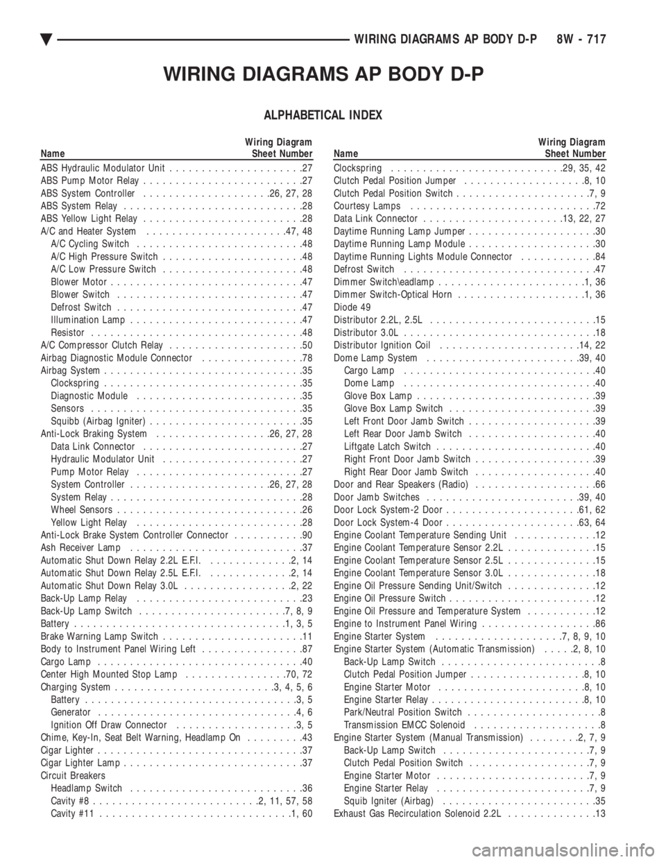
WIRING DIAGRAMS AP BODY D-P
ALPHABETICAL INDEX
Wiring Diagram
Name Sheet Number
ABS Hydraulic Modulator Unit .....................27
ABS Pump Motor Relay .........................27
ABS System Controller ................... .26, 27, 28
ABS System Relay ............................28
ABS Yellow Light Relay .........................28
A/C and Heater System ..................... .47, 48
A/C Cycling Switch ..........................48
A/C High Pressure Switch ......................48
A/C Low Pressure Switch ......................48
Blower Motor ..............................47
Blower Switch .............................47
Defrost Switch .............................47
Illumination Lamp ...........................47
Resistor .................................48
A/C Compressor Clutch Relay .....................50
Airbag Diagnostic Module Connector ................78
Airbag System ...............................35
Clockspring ...............................35
Diagnostic Module ..........................35
Sensors .................................35
Squibb (Airbag Igniter) ........................35
Anti-Lock Braking System ..................26, 27, 28
Data Link Connector .........................27
Hydraulic Modulator Unit ......................27
Pump Motor Relay ..........................27
System Controller ..................... .26, 27, 28
System Relay ..............................28
Wheel Sensors .............................26
Yellow Light Relay ..........................28
Anti-Lock Brake System Controller Connector ...........90
Ash Receiver Lamp ...........................37
Automatic Shut Down Relay 2.2L E.F.I. .............2,14
Automatic Shut Down Relay 2.5L E.F.I. .............2,14
Automatic Shut Down Relay 3.0L .................2,22
Back-Up Lamp Relay ..........................23
Back-Up Lamp Switch .......................7,8,9
Battery .................................1,3,5
Brake Warning Lamp Switch ......................11
Body to Instrument Panel Wiring Left ................87
Cargo Lamp ................................40
Center High Mounted Stop Lamp ................70, 72
Charging System .........................3,4,5,6
Battery .................................3,5
Generator ...............................4,6
Ignition Off Draw Connector ...................3,5
Chime, Key-In, Seat Belt Warning, Headlamp On .........43
Cigar Lighter ................................37
Cigar Lighter Lamp ............................37
Circuit Breakers Headlamp Switch ...........................36
Cavity #8 ..........................2,11,57,58
Cavity #11 ..............................1,60Wiring Diagram
Name Sheet Number
Clockspring .......................... .29, 35, 42
Clutch Pedal Position Jumper ...................8,10
Clutch Pedal Position Switch .....................7,9
Courtesy Lamps .............................72
Data Link Connector ..................... .13, 22, 27
Daytime Running Lamp Jumper ....................30
Daytime Running Lamp Module ....................30
Daytime Running Lights Module Connector ............84
Defrost Switch ..............................47
Dimmer Switch\eadlamp .......................1,36
Dimmer Switch-Optical Horn ....................1,36
Diode 49
Distributor 2.2L, 2.5L ..........................15
Distributor 3.0L ..............................18
Distributor Ignition Coil ..................... .14, 22
Dome Lamp System ....................... .39, 40
Cargo Lamp ..............................40
Dome Lamp ..............................40
Glove Box Lamp ............................39
Glove Box Lamp Switch .......................39
Left Front Door Jamb Switch ....................39
Left Rear Door Jamb Switch ....................40
Liftgate Latch Switch .........................40
Right Front Door Jamb Switch ...................39
Right Rear Door Jamb Switch ...................40
Door and Rear Speakers (Radio) ...................66
Door Jamb Switches ....................... .39, 40
Door Lock System-2 Door .................... .61, 62
Door Lock System-4 Door .................... .63, 64
Engine Coolant Temperature Sending Unit .............12
Engine Coolant Temperature Sensor 2.2L ..............15
Engine Coolant Temperature Sensor 2.5L ..............15
Engine Coolant Temperature Sensor 3.0L ..............18
Engine Oil Pressure Sending Unit/Switch ..............12
Engine Oil Pressure Switch .......................12
Engine Oil Pressure and Temperature System ...........12
Engine to Instrument Panel Wiring ..................86
Engine Starter System ....................7,8,9,10
Engine Starter System (Automatic Transmission) .....2,8,10
Back-Up Lamp Switch .........................8
Clutch Pedal Position Jumper ..................8,10
Engine Starter Motor .......................8,10
Engine Starter Relay ........................8,10
Park/Neutral Position Switch .....................8
Transmission EMCC Solenoid ....................8
Engine Starter System (Manual Transmission) ........2,7,9
Back-Up Lamp Switch .......................7,9
Clutch Pedal Position Switch ...................7,9
Engine Starter Motor ........................7,9
Engine Starter Relay ........................7,9
Squib Igniter (Airbag) ........................35
Exhaust Gas Recirculation Solenoid 2.2L ..............13
Ä WIRING DIAGRAMS AP BODY D-P 8W - 717
Page 1468 of 2438
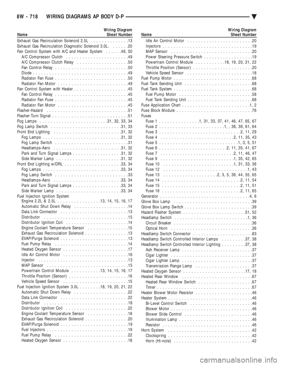
Wiring Diagram
Name Sheet Number
Exhaust Gas Recirculation Solenoid 2.5L ..............13
Exhaust Gas Recirculation Diagnostic Solenoid 3.0L. ......20
Fan Control System with A/C and Heater System ......49, 50
A/C Compressor Clutch .......................49
A/C Compressor Clutch Relay ...................50
Fan Control Relay ...........................50
Diode ...................................49
Radiator Fan Fuse ...........................50
Radiator Fan Motor ..........................49
Fan Control System with Heater ....................45
Fan Control Relay ...........................45
Radiator Fan Fuse ...........................45
Radiator Fan Motor ..........................45
Flasher-Hazard ..............................51
Flasher-Turn Signal ............................51
Fog Lamps ........................ .31, 32, 33, 34
Fog Lamp Switch ......................... .31, 33
Front End Lighting ........................ .31, 32
Fog Lamps ............................ .31, 32
Fog Lamp Switch ...........................31
Headlamps-Aero ........................ .31, 32
Park and Turn Signal Lamps ..................31, 32
Side Marker Lamp ....................... .31, 32
Front End Lighting w/DRL .................... .33, 34
Fog Lamps ............................ .33, 34
Fog Lamp Switch ...........................33
Headlamps-Aero ........................ .33, 34
Park and Turn Signal Lamps ..................33, 34
Side Marker Lamp ....................... .33, 34
Fuel Injection Ignition System Engine 2.2L & 2.5L ............... .13, 14, 15, 16, 17
Automatic Shut Down Relay ....................14
Data Link Connector .........................13
Distributor ...............................15
Distributor Ignition Coil .......................14
Engine Coolant Temperature Sensor ...............15
Exhaust Gas Recirculation Solenoid ................13
EVAP/Purge Solenoid .........................13
Fuel Pump Relay ...........................14
Heated Oxygen Sensor ........................17
Idle Air Control Motor ........................16
Injector .................................13
MAP Sensor ..............................15
Powertrain Control Module ...........13, 14, 15, 16, 17
Throttle Position (Sensor) ......................16
Vehicle Speed Sensor ........................15
Fuel Injection Ignition System 3.0L ........18, 19, 20, 21, 22
Automatic Shut Down Relay ....................22
Data Link Connector .........................22
Distributor ...............................18
Distributor Ignition Coil .......................22
Engine Coolant Temperature Sensor ...............18
Exhaust Gas Recirculation Solenoid ................20
EVAP/Purge Solenoid .........................19
Fuel Injectors ..............................19
Fuel Pump Relay ...........................22
Heated Oxygen Sensor ........................18Wiring Diagram
Name Sheet Number
Idle Air Control Motor ........................20
Injectors .................................19
MAP Sensor ..............................20
Power Steering Pressure Switch ..................19
Powertrain Control Module ...........18, 19, 20, 21, 22
Throttle Position (Sensor) ......................20
Vehicle Speed Sensor ........................18
Fuel Pump Motor .............................68
Fuel Tank Sending Unit .........................68
Fuel Tank System .............................68
Fuel Pump Motor ...........................58
Fuel Tank Sending Unit ........................68
Fuse Application Char t.........................1,2
Fuse Block Module ............................76
Fuses Fuse 1 ...............1,31,33,37,41,46,47,65,67
Fuse 2 ........................1,,36,39,61,64
Fuse 3 ..............................2,11,29
Fuse 4 ...........................2,11,35,43
Fuse 5 .............................1,3,5,51
Fuse 6 .........................2,11,35,41,67
Fuse 7 ...........................2,11,46,47
Fuse 9 ...........................1,35,42,65
Fuse 10 ..........................1,31,33,36
Fuse 12 ...............................1,43
Fuse 13 ....................2,3,5,39,44,55,65
Fuse 14 .............................2,11,54
Fuse 15 .............................2,11,51
Fuse 16 .............................2,11,65
Generator .................................4,6
Glove Box Lamp .............................39
Glove Box Lamp Switch .........................39
Hazard Flasher System ...................... .51, 52
Headlamp Switch ...........................1,36
Circuit Breaker .............................36
Optical Horn ..............................36
Headlamp Switch Connector ......................83
Headlamp Switch Controlled Interior Lamps .........37, 38
Headlamp Switch Controlled Interior Lighting .........37, 38
Ash Receiver Lamp ..........................37
Cigar Lighter ..............................37
Cigar Lighter Lamp ..........................37
Transmission Range Lamp .....................37
Heated Oxygen Sensor ...................... .17, 18
Heated Rear Window ..........................67
Heated Rear Window Switch ....................67
Timer ...................................67
Heater Blower Motor Resistor .....................46
Heater System ...............................46
Bi-Level Control Switch .......................46
Blower Motor ..............................46
Blower Slide Control .........................46
Illumination Lamp ...........................46
Resistor .................................46
Horn System ...............................42
Clockspring ...............................42
Horn (Hi-note) .............................42
8W - 718 WIRING DIAGRAMS AP BODY D-P Ä
Page 1469 of 2438
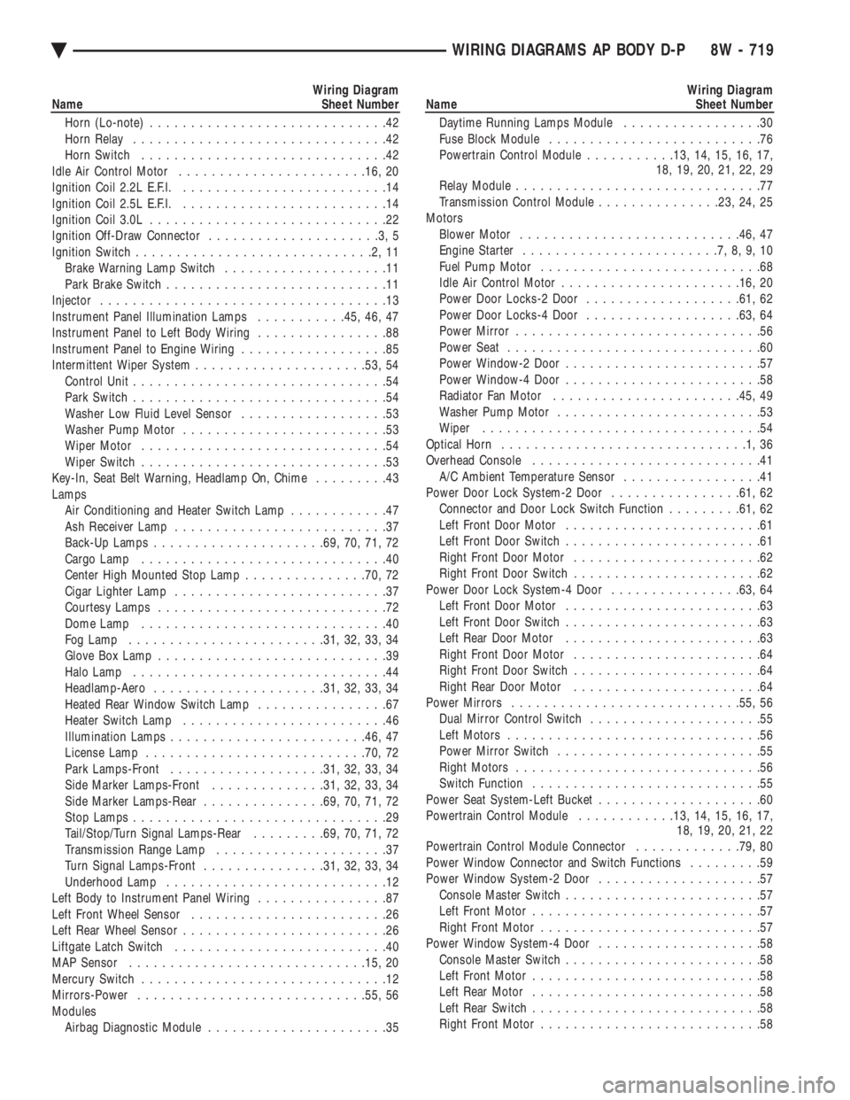
Wiring Diagram
Name Sheet Number
Horn (Lo-note) .............................42
Horn Relay ...............................42
Horn Switch ..............................42
Idle Air Control Motor ...................... .16, 20
Ignition Coil 2.2L E.F.I. .........................14
Ignition Coil 2.5L E.F.I. .........................14
Ignition Coil 3.0L .............................22
Ignition Off-Draw Connector .....................3,5
Ignition Switch .............................2,11
Brake Warning Lamp Switch ....................11
Park Brake Switch ...........................11
Injector ...................................13
Instrument Panel Illumination Lamps ...........45, 46, 47
Instrument Panel to Left Body Wiring ................88
Instrument Panel to Engine Wiring ..................85
Intermittent Wiper System .................... .53, 54
Control Unit ...............................54
Park Switch ...............................54
Washer Low Fluid Level Sensor ..................53
Washer Pump Motor .........................53
Wiper Motor ..............................54
Wiper Switch ..............................53
Key-In, Seat Belt Warning, Headlamp On, Chime .........43
Lamps Air Conditioning and Heater Switch Lamp ............47
Ash Receiver Lamp ..........................37
Back-Up Lamps .................... .69, 70, 71, 72
Cargo Lamp ..............................40
Center High Mounted Stop Lamp ...............70, 72
Cigar Lighter Lamp ..........................37
Courtesy Lamps ............................72
Dome Lamp ..............................40
Fog Lamp ....................... .31, 32, 33, 34
Glove Box Lamp ............................39
Halo Lamp ...............................44
Headlamp-Aero .................... .31, 32, 33, 34
Heated Rear Window Switch Lamp ................67
Heater Switch Lamp .........................46
Illumination Lamps ....................... .46, 47
License Lamp .......................... .70, 72
Park Lamps-Front .................. .31, 32, 33, 34
Side Marker Lamps-Front ..............31, 32, 33, 34
Side Marker Lamps-Rear ...............69, 70, 71, 72
Stop Lamps ...............................29
Tail/Stop/Turn Signal Lamps-Rear .........69, 70, 71, 72
Transmission Range Lamp .....................37
Turn Signal Lamps-Front ...............31, 32, 33, 34
Underhood Lamp ...........................12
Left Body to Instrument Panel Wiring ................87
Left Front Wheel Sensor ........................26
Left Rear Wheel Sensor .........................26
Liftgate Latch Switch ..........................40
MAP Sensor ............................ .15, 20
Mercury Switch ..............................12
Mirrors-Power ........................... .55, 56
Modules Airbag Diagnostic Module ......................35Wiring Diagram
Name Sheet Number
Daytime Running Lamps Module .................30
Fuse Block Module ..........................76
Powertrain Control Module ...........13, 14, 15, 16, 17,
18, 19, 20, 21, 22, 29
Relay Module ..............................77
Transmission Control Module ...............23, 24, 25
Motors Blower Motor .......................... .46, 47
Engine Starter ........................7,8,9,10
Fuel Pump Motor ...........................68
Idle Air Control Motor ..................... .16, 20
Power Door Locks-2 Door .................. .61, 62
Power Door Locks-4 Door .................. .63, 64
Power Mirror ..............................56
Power Seat ...............................60
Power Window-2 Door ........................57
Power Window-4 Door ........................58
Radiator Fan Motor ...................... .45, 49
Washer Pump Motor .........................53
Wiper ..................................54
Optical Horn ..............................1,36
Overhead Console ............................41
A/C Ambient Temperature Sensor .................41
Power Door Lock System-2 Door ................61, 62
Connector and Door Lock Switch Function .........61, 62
Left Front Door Motor ........................61
Left Front Door Switch ........................61
Right Front Door Motor .......................62
Right Front Door Switch .......................62
Power Door Lock System-4 Door ................63, 64
Left Front Door Motor ........................63
Left Front Door Switch ........................63
Left Rear Door Motor ........................63
Right Front Door Motor .......................64
Right Front Door Switch .......................64
Right Rear Door Motor .......................64
Power Mirrors ........................... .55, 56
Dual Mirror Control Switch .....................55
Left Motors ...............................56
Power Mirror Switch .........................55
Right Motors ..............................56
Switch Function ............................55
Power Seat System-Left Bucket ....................60
Powertrain Control Module ............13, 14, 15, 16, 17,
18, 19, 20, 21, 22
Powertrain Control Module Connector .............79, 80
Power Window Connector and Switch Functions .........59
Power Window System-2 Door ....................57
Console Master Switch ........................57
Left Front Motor ............................57
Right Front Motor ...........................57
Power Window System-4 Door ....................58
Console Master Switch ........................58
Left Front Motor ............................58
Left Rear Motor ............................58
Left Rear Switch ............................58
Right Front Motor ...........................58
Ä WIRING DIAGRAMS AP BODY D-P 8W - 719
Page 1470 of 2438
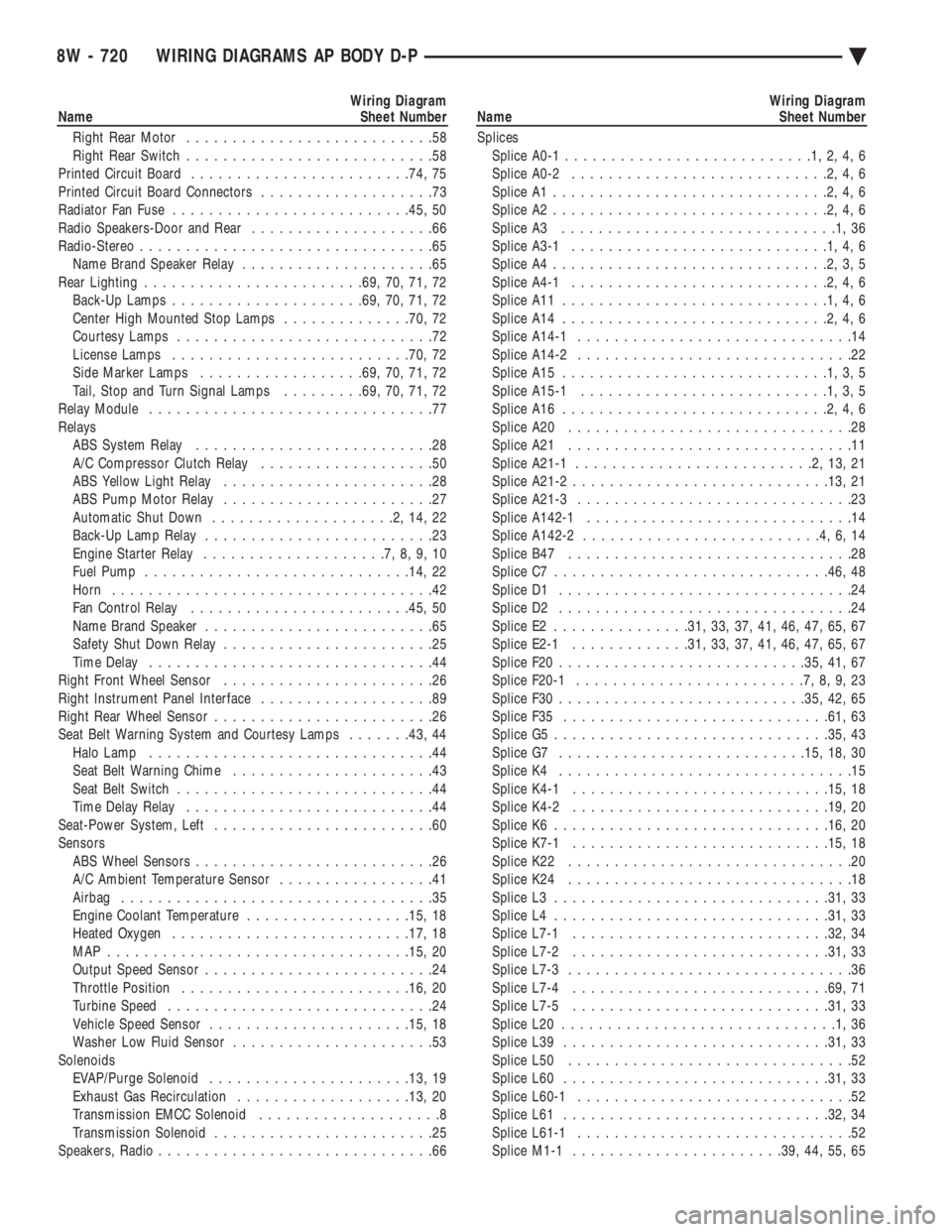
Wiring Diagram
Name Sheet Number
Right Rear Motor ...........................58
Right Rear Switch ...........................58
Printed Circuit Board ....................... .74, 75
Printed Circuit Board Connectors ...................73
Radiator Fan Fuse ......................... .45, 50
Radio Speakers-Door and Rear ....................66
Radio-Stereo ................................65
Name Brand Speaker Relay .....................65
Rear Lighting ....................... .69, 70, 71, 72
Back-Up Lamps .................... .69, 70, 71, 72
Center High Mounted Stop Lamps ..............70, 72
Courtesy Lamps ............................72
License Lamps ......................... .70, 72
Side Marker Lamps ................. .69, 70, 71, 72
Tail, Stop and Turn Signal Lamps .........69, 70, 71, 72
Relay Module ...............................77
Relays ABS System Relay ..........................28
A/C Compressor Clutch Relay ...................50
ABS Yellow Light Relay .......................28
ABS Pump Motor Relay .......................27
Automatic Shut Down ....................2,14,22
Back-Up Lamp Relay .........................23
Engine Starter Relay ....................7,8,9,10
Fuel Pump ............................ .14, 22
Horn ...................................42
Fan Control Relay ....................... .45, 50
Name Brand Speaker .........................65
Safety Shut Down Relay .......................25
Time Delay ...............................44
Right Front Wheel Sensor .......................26
Right Instrument Panel Interface ...................89
Right Rear Wheel Sensor ........................26
Seat Belt Warning System and Courtesy Lamps .......43, 44
Halo Lamp ...............................44
Seat Belt Warning Chime ......................43
Seat Belt Switch ............................44
Time Delay Relay ...........................44
Seat-Power System, Left ........................60
Sensors ABS Wheel Sensors ..........................26
A/C Ambient Temperature Sensor .................41
Airbag ..................................35
Engine Coolant Temperature ..................15, 18
Heated Oxygen ......................... .17, 18
MAP ................................ .15, 20
Output Speed Sensor .........................24
Throttle Position ........................ .16, 20
Turbine Speed .............................24
Vehicle Speed Sensor ..................... .15, 18
Washer Low Fluid Sensor ......................53
Solenoids EVAP/Purge Solenoid ..................... .13, 19
Exhaust Gas Recirculation .................. .13, 20
Transmission EMCC Solenoid ....................8
Transmission Solenoid ........................25
Speakers, Radio ..............................66Wiring Diagram
Name Sheet Number
Splices Splice A0-1 ...........................1,2,4,6
Splice A0-2 ............................2,4,6
Splice A1 ..............................2,4,6
Splice A2 ..............................2,4,6
Splice A3 ..............................1,36
Splice A3-1 ............................1,4,6
Splice A4 ..............................2,3,5
Splice A4-1 ............................2,4,6
Splice A11 .............................1,4,6
Splice A14 .............................2,4,6
Splice A14-1 ..............................14
Splice A14-2 ..............................22
Splice A15 .............................1,3,5
Splice A15-1 ...........................1,3,5
Splice A16 .............................2,4,6
Splice A20 ...............................28
Splice A21 ...............................11
Splice A21-1 ..........................2,13,21
Splice A21-2 ........................... .13, 21
Splice A21-3 ..............................23
Splice A142-1 .............................14
Splice A142-2 ..........................4,6,14
Splice B47 ...............................28
Splice C7 ............................. .46, 48
Splice D1 ................................24
Splice D2 ................................24
Splice E2 .............. .31, 33, 37, 41, 46, 47, 65, 67
Splice E2-1 ............ .31, 33, 37, 41, 46, 47, 65, 67
Splice F20 .......................... .35, 41, 67
Splice F20-1 .........................7,8,9,23
Splice F30 .......................... .35, 42, 65
Splice F35 ............................ .61, 63
Splice G5 ............................. .35, 43
Splice G7 .......................... .15, 18, 30
Splice K4 ................................15
Splice K4-1 ........................... .15, 18
Splice K4-2 ........................... .19, 20
Splice K6 ............................. .16, 20
Splice K7-1 ........................... .15, 18
Splice K22 ...............................20
Splice K24 ...............................18
Splice L3 ............................. .31, 33
Splice L4 ............................. .31, 33
Splice L7-1 ........................... .32, 34
Splice L7-2 ........................... .31, 33
Splice L7-3 ...............................36
Splice L7-4 ........................... .69, 71
Splice L7-5 ........................... .31, 33
Splice L20 ..............................1,36
Splice L39 ............................ .31, 33
Splice L50 ...............................52
Splice L60 ............................ .31, 33
Splice L60-1 ..............................52
Splice L61 ............................ .32, 34
Splice L61-1 ..............................52
Splice M1-1 ...................... .39, 44, 55, 65
8W - 720 WIRING DIAGRAMS AP BODY D-P Ä