1993 CHEVROLET DYNASTY jump start
[x] Cancel search: jump startPage 391 of 2438
GENERATOR TEST PROCEDURES ON VEHICLE INDEX
page page
Charging System Diagnostics (Fig. 1) ......... 19
Current Output Test ...................... 19 Output Wire Resistance Test
................ 19
CHARGING SYSTEM DIAGNOSTICS (Fig. 1)
OUTPUT WIRE RESISTANCE TEST
The generator output wire resistance test shows
the amount of voltage drop across the generator out-
put wire between the generator B+ terminal and the
positive battery post.
PREPARATION
Before starting test, make sure the vehicle has a
fully charged battery. Tests and procedures to check
for a fully charged battery is shown in the Battery
section. (1) Turn the ignition switch OFF.
(2) Disconnect battery NEGATIVE cable.
(3) Disconnect the generator B+ output wire from
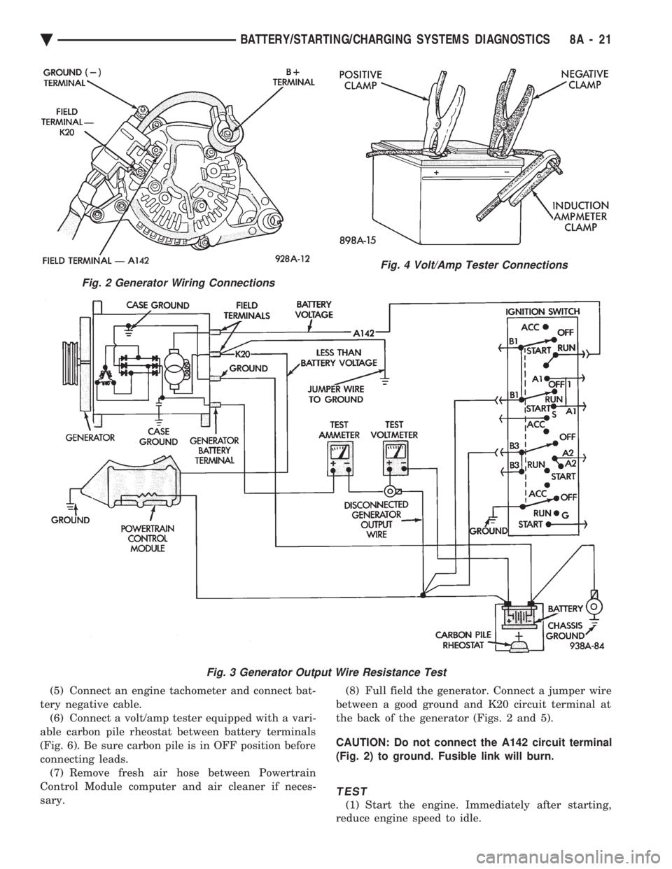
the generator output battery terminal (Fig. 2). (4) Connect a 0-150 ampere scale (DC) ammeter in
series between B+ terminal and output wire (Fig. 2
and 3). Connect positive lead to B+ terminal, and
negative lead to output wire. (5) Using o-18 volt scale voltmeter, connect the
positive lead to the disconnected (B+) output wire
(Fig. 2). Connect the negative lead to positive battery
post. (6) Remove fresh air hose between Powertrain
Control Module and air cleaner if necessary. (7) Connect jumper wire between a good ground
and K20 circuit terminal at the back of the genera-
tor.
CAUTION: Do not connect the A142 circuit terminal
(Fig. 2) to ground the Fusible link will burn.
(8) Connect an engine tachometer and connect bat-
tery negative cable. (10) Connect a volt/amp tester equipped with a
variable carbon pile rheostat between battery termi-
nals (Fig. 4).
Caution: Be sure the carbon pile is in OFF position
before connecting leads.
TEST
(1) Start engine. Immediately after starting, re-
duce engine speed to idle. (2) Adjust engine speed and carbon pile to main-
tain 20 amperes flowing in the circuit. Observe volt-
meter reading. Voltmeter reading should not exceed
0.5 volts.
RESULTS
If a higher voltage drop is shown, inspect, clean
and tighten all connections between generator B+
terminal and battery positive post. A voltage drop
test may be performed at each connection to locate a
connection with excessive resistance. If resistance
tests are satisfactory, reduce engine speed, turn off
carbon pile, and turn off ignition switch. (1) Disconnect battery negative cable.
(2) Remove test ammeter, voltmeter, carbon pile,
and tachometer. (3) Remove jumper wire.
(4) Connect generator output wire to generator B+
terminal. (5) Connect battery negative cable.
(6) Connect fresh air hose between Powertrain
Control Module and air cleaner if removed.
CURRENT OUTPUT TEST
The current output test decides whether the gener-
ator can deliver its rated current output. For gener-
ator identification and output amperage
specifications, refer to Generator Specifications. For generator maximum voltage at individual tem-
peratures, refer to Generator Output Voltage Specifi-
cations.
PREPARATION
Before starting any tests, make sure the vehicle
has a fully charged battery. Tests and procedures to
check for a fully charged battery is shown in Battery
section. (1) Disconnect battery negative cable.
(2) Disconnect output wire at the B+ terminal
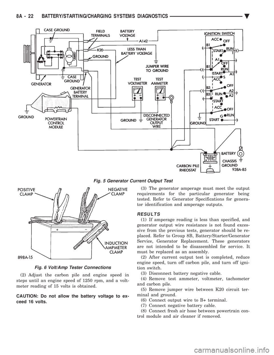
(Figs. 2 and 5). (3) Connect a 0-150 ampere scale (DC) ammeter in
series between the B+ terminal and output wire.
Connect Positive lead to B+ terminal and negative
lead to output wire. (4) Using 0-18 voltmeter, connect positive lead to
B+ terminal (Figs. 2 and 5). Connect negative lead
to a good ground.
Ä BATTERY/STARTING/CHARGING SYSTEMS DIAGNOSTICS 8A - 19
Page 393 of 2438
(5) Connect an engine tachometer and connect bat-
tery negative cable. (6) Connect a volt/amp tester equipped with a vari-
able carbon pile rheostat between battery terminals
(Fig. 6). Be sure carbon pile is in OFF position before
connecting leads. (7) Remove fresh air hose between Powertrain
Control Module computer and air cleaner if neces-
sary. (8) Full field the generator. Connect a jumper wire
between a good ground and K20 circuit terminal at
the back of the generator (Figs. 2 and 5).
CAUTION: Do not connect the A142 circuit terminal
(Fig. 2) to ground. Fusible link will burn.
TEST
(1) Start the engine. Immediately after starting,
reduce engine speed to idle.
Fig. 2 Generator Wiring Connections
Fig. 3 Generator Output Wire Resistance Test
Fig. 4 Volt/Amp Tester Connections
Ä BATTERY/STARTING/CHARGING SYSTEMS DIAGNOSTICS 8A - 21
Page 394 of 2438
(2) Adjust the carbon pile and engine speed in
steps until an engine speed of 1250 rpm, and a volt-
meter reading of 15 volts is obtained.
CAUTION: Do not allow the battery voltage to ex-
ceed 16 volts. (3) The generator amperage must meet the output
requirements for the particular generator being
tested. Refer to Generator Specifications for genera-
tor identification and amperage outputs.
RESULTS
(1) If amperage reading is less than specified, and
generator output wire resistance is not found exces-
sive from the previous tests, generator should be re-
placed. Refer to Group 8B, Battery/Starter/Generator
Service, Generator Replacement. These generators
are not intended to be disassembled for service. It
must be replaced as an assembly. (2) After current output test is completed, reduce
engine speed, turn off carbon pile, and turn off igni-
tion switch. (3) Disconnect battery negative cable.
(4) Remove test ammeter, voltmeter, tachometer
and carbon pile. (5) Remove jumper wire between K20 circuit ter-
minal and ground. (6) Connect output wire to B+ terminal.
(7) Connect negative battery cable.
(8) Connect fresh air hose between powertrain con-
trol module and air cleaner if removed.
Fig. 5 Generator Current Output Test
Fig. 6 Volt/Amp Tester Connections
8A - 22 BATTERY/STARTING/CHARGING SYSTEMS DIAGNOSTICS Ä
Page 454 of 2438

make sure that the spark plugs are firing. Inspect the
distributor rotor, cap, spark plug cables, and spark
plugs. If they are in proper working order, the ignition
system is not the reason why the engine will not start.
Inspect the fuel system and engine for proper opera-
tion.
FAILURE TO START TESTÐ2.5L TBI AND 3.0L
ENGINES
Before proceeding with this test make sure
Testing For Spark At Coil has been performed.
Failure to do this may lead to unnecessary diag-
nostic time and wrong test results.
WARNING: BE SURE TO APPLY PARKING BRAKE
AND/OR BLOCK WHEELS BEFORE PERFORMING
ANY TEST WITH THE ENGINE RUNNING.
(1) Battery voltage must be at least 12.4 volts to
perform test. (2) Crank the engine for 5 seconds while monitoring
the voltage at the coil positive (+) terminal (Fig. 2 or
Fig. 3). If the voltage remains near zero during the
entire period of cranking, refer to Group 14 for On-
Board Diagnostic checks. Also, refer to the DRBII scan
tool and the appropriate Powertrain Diagnostic Proce-
dures manual. These checks will help diagnose prob-
lems with the PCM and auto shutdown relay. (3) If voltage is at near-battery voltage and drops to
zero after 1-2 seconds of cranking, refer to On-Board
Diagnostic in Group 14. Also, refer to the DRBII scan
tool and the appropriate Powertrain Diagnostic Proce-
dures manual. These tests will help check the distribu-
tor reference pickup circuit to the PCM. (4) If voltage remains at near battery voltage during
the entire 5 seconds, with the key off,remove the
PCM 60-way connector. Check the 60-way connector
for any terminals that are pushed out or loose. (5) Remove the connector to coil (+) and connect a
jumper wire between battery (+) and coil (+). (6) Using the special jumper (Fig. 4), momentarily ground terminal #19 of the 60-way connector (Fig.
5). A spark should be generated when the ground is
removed.
(7) If spark is generated, replace the PCM.
(8) If no spark is seen, use the special jumper to
ground the coil (-) terminal directly. (9) If spark is produced, inspect wiring harness for
an open condition.
Fig. 2 Coil TerminalsÐ2.2L TBI, 2.5L TBI and 2.5L MPI Engines
Fig. 3 Coil TerminalsÐ3.0L Engine
Fig. 4 Special Jumper to Ground Coil Negative
Fig. 1 Checking for Spark
8D - 12 IGNITION SYSTEMS Ä
Page 483 of 2438

(2) With engine running, move test probe along
entire length of all cables (approximately 0 to 1/8
inch gap). If punctures or cracks are present there
will be a noticeable spark jump from the faulty area
to the probe. Cracked, leaking or faulty cables should
be replaced. Use the following procedure when removing the
high tension cable from the spark plug. First, remove
the cable from the retaining bracket. Then grasp the
terminal as close as possible to the spark plug. Ro-
tate the cover (boot) slightly and pull straight back.
Do not use pliers and do not pull the cable at an
angle. Doing so will damage the insulation, cable
terminal or the spark plug insulator. Wipe spark
plug insulator clean before reinstalling cable
and cover. Resistance cables are identified by the words Elec-
tronic Suppression .
Use an ohmmeter to check cables for opens, loose
terminals or high resistance. (a) Remove cable from spark plug.
(b) Remove cable from the coil tower.
(c) Connect the ohmmeter between spark plug
end terminal and the coil end terminal. Resistance
should be within tolerance shown in the cable re-
sistance chart. If resistance is not within tolerance,
replace cable assembly. Test all spark plug cables
in same manner.
SPARK PLUG SERVICE
When replacing the spark plug cables, route the ca-
bles correctly and secure them in the appropriate re-
tainers. Incorrectly routed cables can cause the radio
to reproduce ignition noise. It can also cause cross ig-
nition of the spark plugs or short circuit the cables to
ground.
SPARK PLUG REMOVAL
Always remove cables by grasping at boot, rotating
the boot 1/2 turn, and pulling straight back in a
steady motion. (1) Prior to removing the spark plug spray com-
pressed air around the spark plug hole and the area
around the spark plug. (2) Remove the spark plug using a quality socket
with a rubber or foam insert. (3) Inspect the spark plug condition. Refer to
Spark Plug Condition in this section.
SPARK PLUG GAP ADJUSTMENT
Check the spark plug gap with a gap gauge. If the
gap is not correct, adjust it by bending the ground
electrode (Fig. 6).
SPARK PLUG INSTALLATION
(1) To avoid cross threading, start the spark plug
into the cylinder head by hand. (2) Tighten spark plugs to 28 N Im (20 ft. lbs.)
torque. (3) Install spark plug cables over spark plugs.
IDLE RPM TEST
WARNING: BE SURE TO APPLY PARKING BRAKE
AND/OR BLOCK WHEELS BEFORE PERFORMING
ANY ENGINE RUNNING TESTS.
Engine idle set rpmshould be tested and recorded
as it is when the vehicle is first brought into shop
for testing. This will assist in diagnosing complaints
of engine stalling, creeping and hard shifting on ve-
hicles equipped with automatic transaxle. Refer to the
Throttle Body Minimum Airflow procedures in Group
14.
IGNITION TIMING PROCEDURE
Ignition timing cannot be changed or set on Turbo
III, 3.3L or 3.8L engines. For diagnostic information,
refer to the DRBII scan tool and the appropriate
Powertrain Diagnostics Procedures manual.
CABLE RESISTANCE CHART
Fig. 6 Setting Spark Plug GapÐTypical
Ä IGNITION SYSTEMS 8D - 41
Page 495 of 2438
SENDING UNIT TEST
When a problem occurs with a cluster gauge, be-
fore disassembling the cluster to check the gauge,
check for a defective sending unit or wiring. (1) Sending units and wiring can be checked by
grounding the connector leads, at the sending unit,
in the vehicle. (2) With the ignition in the ON position; a
grounded input will cause the oil, fuel or tempera-
ture gauge to read at or above maximum.
LOW OIL PRESSURE/CHECK GAUGES WARNING LAMP TEST
The low oil pressure/check gauges warning lamp
will illuminate when the ignition key is turned to
the ON position without starting the vehicle. In the cluster assembly without tachometer, the
low oil pressure lamp will illuminate if the engine oil
pressure drops below a safe oil pressure level. In the cluster assembly with tachometer, the Check
Gauges warning lamp illuminates when there is a
problem in oil pressure level, high engine tempera-
ture or low voltage. To test the system turn ignition key to the ON po-
sition. If the lamp fails to light, inspect for a broken
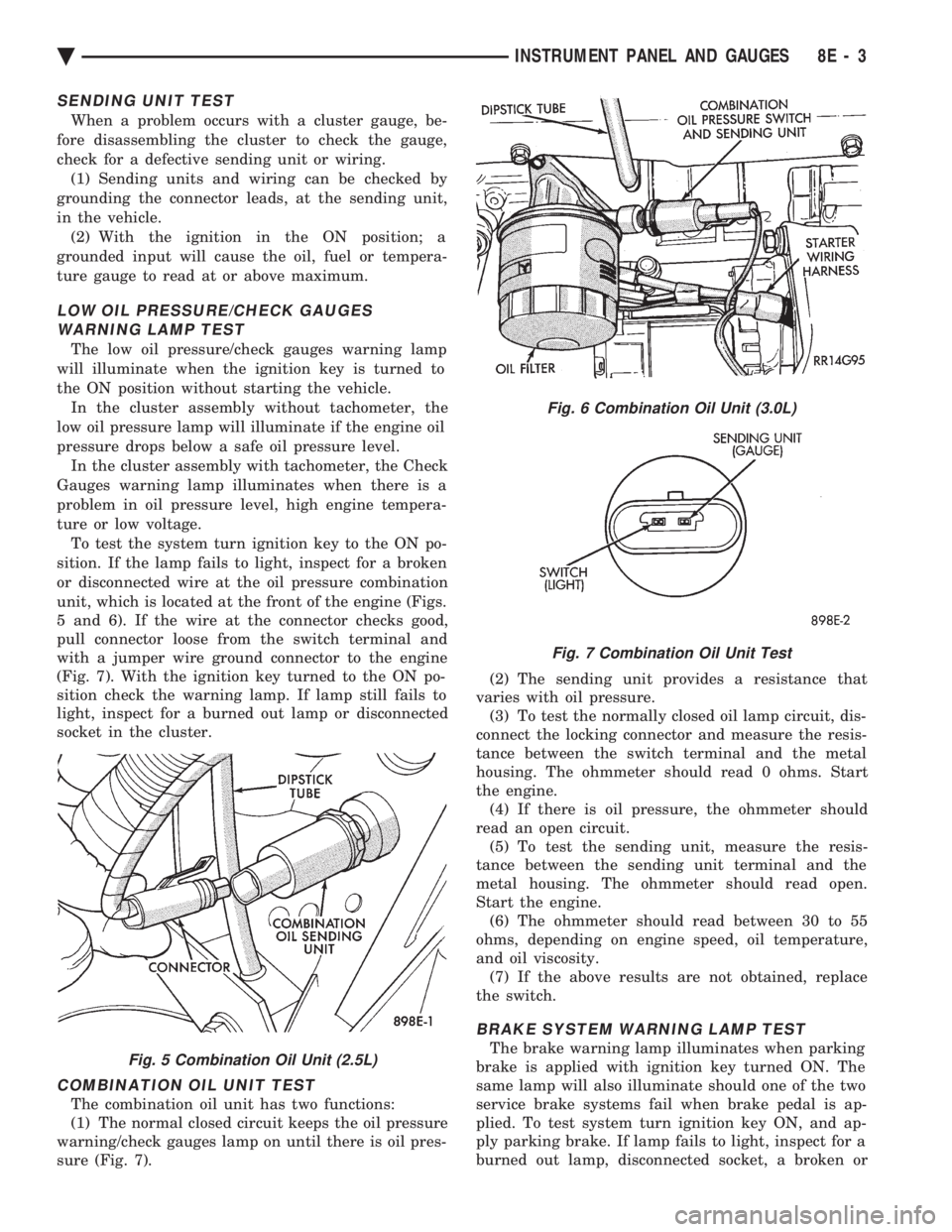
or disconnected wire at the oil pressure combination
unit, which is located at the front of the engine (Figs.
5 and 6). If the wire at the connector checks good,
pull connector loose from the switch terminal and
with a jumper wire ground connector to the engine
(Fig. 7). With the ignition key turned to the ON po-
sition check the warning lamp. If lamp still fails to
light, inspect for a burned out lamp or disconnected
socket in the cluster.
COMBINATION OIL UNIT TEST
The combination oil unit has two functions:
(1) The normal closed circuit keeps the oil pressure
warning/check gauges lamp on until there is oil pres-
sure (Fig. 7). (2) The sending unit provides a resistance that
varies with oil pressure. (3) To test the normally closed oil lamp circuit, dis-
connect the locking connector and measure the resis-
tance between the switch terminal and the metal
housing. The ohmmeter should read 0 ohms. Start
the engine. (4) If there is oil pressure, the ohmmeter should
read an open circuit. (5) To test the sending unit, measure the resis-
tance between the sending unit terminal and the
metal housing. The ohmmeter should read open.
Start the engine. (6) The ohmmeter should read between 30 to 55
ohms, depending on engine speed, oil temperature,
and oil viscosity. (7) If the above results are not obtained, replace
the switch.
BRAKE SYSTEM WARNING LAMP TEST
The brake warning lamp illuminates when parking
brake is applied with ignition key turned ON. The
same lamp will also illuminate should one of the two
service brake systems fail when brake pedal is ap-
plied. To test system turn ignition key ON, and ap-
ply parking brake. If lamp fails to light, inspect for a
burned out lamp, disconnected socket, a broken orFig. 5 Combination Oil Unit (2.5L)
Fig. 6 Combination Oil Unit (3.0L)
Fig. 7 Combination Oil Unit Test
Ä INSTRUMENT PANEL AND GAUGES 8E - 3
Page 539 of 2438
(3) With the ignition switch ON, an open (discon-
nected sending unit wire) causes the oil, fuel or tem-
perature gauge to read below low, empty or cold
indicators. (4) If steps 2 and 3 check OK, refer to the individ-
ual sending unit test procedures.
FUEL TANK SENDING UNIT TEST
Refer to Group 14, Fuel for test procedure.
CHECK GAUGES WARNING LAMP TESTS
The check gauges warning lamp will illuminated
when the ignition key is turned to the ON position.
The lamp will illuminate if the engine oil pressure
drops below a safe level. The check gauge lamp will
light for high engine temperature or for low voltage. To test the system turn ignition key to the ON po-
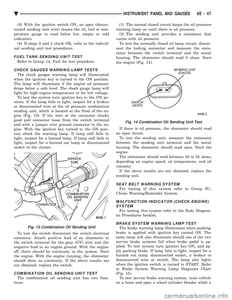
sition. If the lamp fails to light, inspect for a broken
or disconnected wire at the oil pressure combination
sending unit, which is located at the front of the en-
gine (Fig. 13). If the wire at the connector checks
good pull connector loose from the switch terminal
and with a jumper wire ground connector to the en-
gine. With the ignition key turned to the ON posi-
tion check the warning lamp. If lamp still fails to
light, inspect for a burned lamp. If lamp still fails to
light, inspect for a burned out lamp or disconnected
socket in the cluster.
To test the switch disconnect the switch electrical
connector. Attach positive lead of an ohmmeter to
the switch terminal for the gray (GY) wire and the
negative lead to an engine ground. With the engine
off, there should be continuity in the system. Start
the engine. With the engine running, the ohmmeter
should show no continuity. If the above results are
not obtained, replace the switch.
COMBINATION OIL SENDING UNIT TEST
The combination oil sending unit has two func-
tions: (1) The normal closed circuit keeps the oil pressure
warning lamp on until there is oil pressure. (2) The sending unit provides a resistance that
varies with oil pressure. To test the normally closed oil lamp circuit, discon-
nect the locking connector and measure the resis-
tance between the switch terminal and the metal
housing. The ohmmeter should read 0 ohms. Start
the engine (Fig. 14).
If there is oil pressure, the ohmmeter should read
an open circuit. To test the sending unit, measure the resistance
between the sending unit terminal and the metal
housing. The ohmmeter should read open. Start the
engine. The ohmmeter should read between 30 to 55 ohms,
depending on engine speed, oil temperature, and oil
viscosity. If the above results are not obtained, replace the
sending unit.
SEAT BELT WARNING SYSTEM
For testing of this system refer to Group 8U,
Chime Warning/Reminder System.
MALFUNCTION INDICATOR (CHECK ENGINE) SYSTEM
For testing this system refer to the Body Diagnos-
tic Procedures booklet.
BRAKE SYSTEM WARNING LAMP TEST
The brake warning lamp illuminates when parking
brake is applied with ignition key turned ON. The
same lamp will also illuminate should one of the two
service brake systems fail when brake pedal is ap-
plied. To test system turn ignition key ON, and ap-
ply parking brake. If lamp fails to light, inspect for a
burned out lamp, disconnected socket, a broken or
disconnected wire at switch. The lamp also lights
when the ignition switch is turned to START. Refer
to Brake System Warning Lamp Diagnosis Chart
(Fig. 15). To test service brake warning system, raise vehicle
on a hoist and open a wheel cylinder bleeder while aFig. 13 Combination Oil Sending Unit
Fig. 14 Combination Oil Sending Unit Test
Ä INSTRUMENT PANEL AND GAUGES 8E - 47
Page 551 of 2438
FUEL TANK SENDING UNIT TEST
Refer to Group 14, Fuel for test procedures.
LOW OIL PRESSURE WARNING LAMP TEST
The low oil pressure warning lamp will illuminate
when the ignition key is turned to the ON position
without engine running. The lamp also illuminates
should the engine oil pressure drop below a safe oil
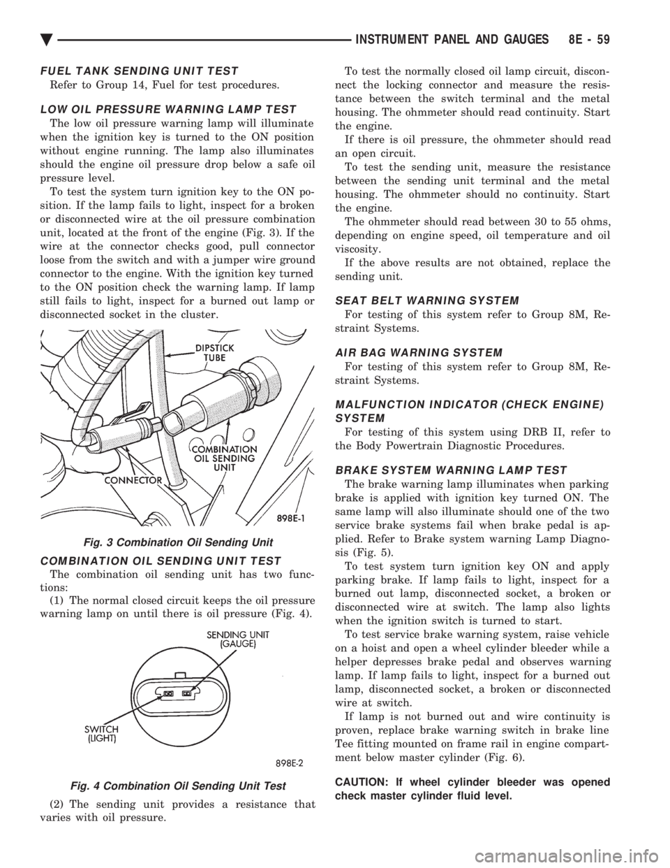
pressure level. To test the system turn ignition key to the ON po-
sition. If the lamp fails to light, inspect for a broken
or disconnected wire at the oil pressure combination
unit, located at the front of the engine (Fig. 3). If the
wire at the connector checks good, pull connector
loose from the switch and with a jumper wire ground
connector to the engine. With the ignition key turned
to the ON position check the warning lamp. If lamp
still fails to light, inspect for a burned out lamp or
disconnected socket in the cluster.
COMBINATION OIL SENDING UNIT TEST
The combination oil sending unit has two func-
tions: (1) The normal closed circuit keeps the oil pressure
warning lamp on until there is oil pressure (Fig. 4).
(2) The sending unit provides a resistance that
varies with oil pressure. To test the normally closed oil lamp circuit, discon-
nect the locking connector and measure the resis-
tance between the switch terminal and the metal
housing. The ohmmeter should read continuity. Start
the engine. If there is oil pressure, the ohmmeter should read
an open circuit. To test the sending unit, measure the resistance
between the sending unit terminal and the metal
housing. The ohmmeter should no continuity. Start
the engine. The ohmmeter should read between 30 to 55 ohms,
depending on engine speed, oil temperature and oil
viscosity. If the above results are not obtained, replace the
sending unit.
SEAT BELT WARNING SYSTEM
For testing of this system refer to Group 8M, Re-
straint Systems.
AIR BAG WARNING SYSTEM
For testing of this system refer to Group 8M, Re-
straint Systems.
MALFUNCTION INDICATOR (CHECK ENGINE) SYSTEM
For testing of this system using DRB II, refer to
the Body Powertrain Diagnostic Procedures.
BRAKE SYSTEM WARNING LAMP TEST
The brake warning lamp illuminates when parking
brake is applied with ignition key turned ON. The
same lamp will also illuminate should one of the two
service brake systems fail when brake pedal is ap-
plied. Refer to Brake system warning Lamp Diagno-
sis (Fig. 5). To test system turn ignition key ON and apply
parking brake. If lamp fails to light, inspect for a
burned out lamp, disconnected socket, a broken or
disconnected wire at switch. The lamp also lights
when the ignition switch is turned to start. To test service brake warning system, raise vehicle
on a hoist and open a wheel cylinder bleeder while a
helper depresses brake pedal and observes warning
lamp. If lamp fails to light, inspect for a burned out
lamp, disconnected socket, a broken or disconnected
wire at switch. If lamp is not burned out and wire continuity is
proven, replace brake warning switch in brake line
Tee fitting mounted on frame rail in engine compart-
ment below master cylinder (Fig. 6).
CAUTION: If wheel cylinder bleeder was opened
check master cylinder fluid level.
Fig. 3 Combination Oil Sending Unit
Fig. 4 Combination Oil Sending Unit Test
Ä INSTRUMENT PANEL AND GAUGES 8E - 59