1993 CHEVROLET DYNASTY fuse box
[x] Cancel search: fuse boxPage 547 of 2438
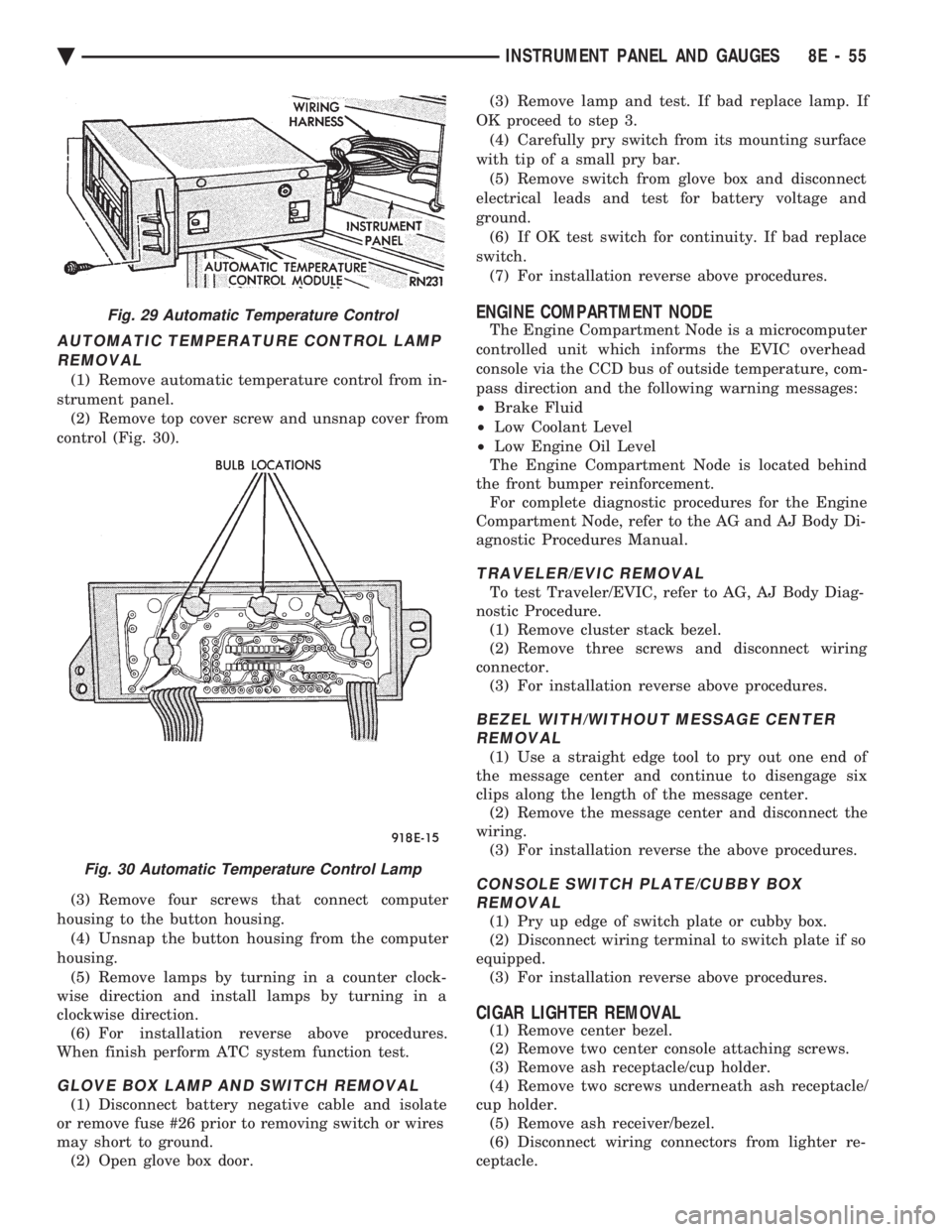
AUTOMATIC TEMPERATURE CONTROL LAMP REMOVAL
(1) Remove automatic temperature control from in-
strument panel. (2) Remove top cover screw and unsnap cover from
control (Fig. 30).
(3) Remove four screws that connect computer
housing to the button housing. (4) Unsnap the button housing from the computer
housing. (5) Remove lamps by turning in a counter clock-
wise direction and install lamps by turning in a
clockwise direction. (6) For installation reverse above procedures.
When finish perform ATC system function test.
GLOVE BOX LAMP AND SWITCH REMOVAL
(1) Disconnect battery negative cable and isolate
or remove fuse #26 prior to removing switch or wires
may short to ground. (2) Open glove box door. (3) Remove lamp and test. If bad replace lamp. If
OK proceed to step 3. (4) Carefully pry switch from its mounting surface
with tip of a small pry bar. (5) Remove switch from glove box and disconnect
electrical leads and test for battery voltage and
ground. (6) If OK test switch for continuity. If bad replace
switch. (7) For installation reverse above procedures.
ENGINE COMPARTMENT NODE
The Engine Compartment Node is a microcomputer
controlled unit which informs the EVIC overhead
console via the CCD bus of outside temperature, com-
pass direction and the following warning messages:
² Brake Fluid
² Low Coolant Level
² Low Engine Oil Level
The Engine Compartment Node is located behind
the front bumper reinforcement. For complete diagnostic procedures for the Engine
Compartment Node, refer to the AG and AJ Body Di-
agnostic Procedures Manual.
TRAVELER/EVIC REMOVAL
To test Traveler/EVIC, refer to AG, AJ Body Diag-
nostic Procedure. (1) Remove cluster stack bezel.
(2) Remove three screws and disconnect wiring
connector. (3) For installation reverse above procedures.
BEZEL WITH/WITHOUT MESSAGE CENTERREMOVAL
(1) Use a straight edge tool to pry out one end of
the message center and continue to disengage six
clips along the length of the message center. (2) Remove the message center and disconnect the
wiring. (3) For installation reverse the above procedures.
CONSOLE SWITCH PLATE/CUBBY BOXREMOVAL
(1) Pry up edge of switch plate or cubby box.
(2) Disconnect wiring terminal to switch plate if so
equipped. (3) For installation reverse above procedures.
CIGAR LIGHTER REMOVAL
(1) Remove center bezel.
(2) Remove two center console attaching screws.
(3) Remove ash receptacle/cup holder.
(4) Remove two screws underneath ash receptacle/
cup holder. (5) Remove ash receiver/bezel.
(6) Disconnect wiring connectors from lighter re-
ceptacle.
Fig. 29 Automatic Temperature Control
Fig. 30 Automatic Temperature Control Lamp
Ä INSTRUMENT PANEL AND GAUGES 8E - 55
Page 549 of 2438

(11) Remove two screws from fuse block and lower
fuse block. (12) Remove three screws from hood release and
lower hood release handle. (13) Remove flasher relay from bracket on center
distribution duct. (14) Remove screw from ATC sensor motor assem-
bly and unhook from bracket if equipped. (15) Remove the radio ground screw above flasher
relay mount. (16) Remove center distribution duct screw from
left instrument panel lower brace, then remove four
screws to remove left lower brace.
(17) Remove five nuts on steering column and drop
column, then remove two upper column attaching studs.
(18) Remove two screws and pull out compact disc
player or cubby box, disconnect Co-Axial cable from
compact disc player. (19) Remove Electronic Vehicle Information Center
(E.V.I.C.) or Traveler from vehicle. (20) Remove radio.
(21) Remove A.T.C., A/C or heater controls. (22) Squeeze latches on side of Rear Window defog-
ger switch and remove. (23) Snap off cluster lower trim bezel, switch pod
vent grille, speaker grilles and defroster grilles. (24) Remove switch pod assembly.
(25) Remove cluster assembly.
(26) Remove dash speakers.
(27) Snap out bezel with or without message center
and disconnect wiring. (28) Open glovebox door, squeeze sides and roll
glovebox completely open. Remove glovebox light
switch, and disconnect wires. (29) Loosen right cowl side pivot bolt through
glovebox opening then close glovebox. (30) Loosen left cowl side pivot.
(31) Remove four screw attachments at top of in-
strument panel and roll panel out. (32) Pull wiring, antenna cable, A/C cable and vac-
uum lines out of instrument panel. Disconnect demis-
ter hose and remove instrument panel with ducts
attached. (33) Transfer ducts and brackets onto new panel.
(34) For instrument panel roll up, reverse
above procedures.
INTERIOR LAMP REMOVAL
The Dome, Floor Console and Door Lamps operate
when the doors are open or headlamp switch is
placed in courtesy position.
DOME LAMP
(1) Pry either the forward or rearward edge of the
dome lamp to free it from retaining bracket. (2) Pry either the forward or rearward edge of the
lens away from the bezel and replace lamp. (3) For installation reverse above procedures.
FRONT HEADER READING LAMP
Pull lamp from headliner. Disconnect wiring and
replace lamp.
FLOOR CONSOLE LAMP
Pry along top edge of lamp and pivot lamp out of
floor console, the lens does not remove. Remove lamp
and twist out lamp socket. Replace lamp.
DOOR LAMPS
Pry along bottom edge of lamp and pivot lamp out
of door trim panel, the lens does not remove. Remove
lamp and twist out lamp socket. Replace lamp.
DOOR REFLECTORS
Pry reflector away from the door trim panel, and
replace.
TRUNK LAMP
Remove lens by prying lens out of trunk trim panel
and replace bulb.
Fig. 33 Transmission Range Cable
Fig. 34 Cable Adjustment
Ä INSTRUMENT PANEL AND GAUGES 8E - 57
Page 561 of 2438
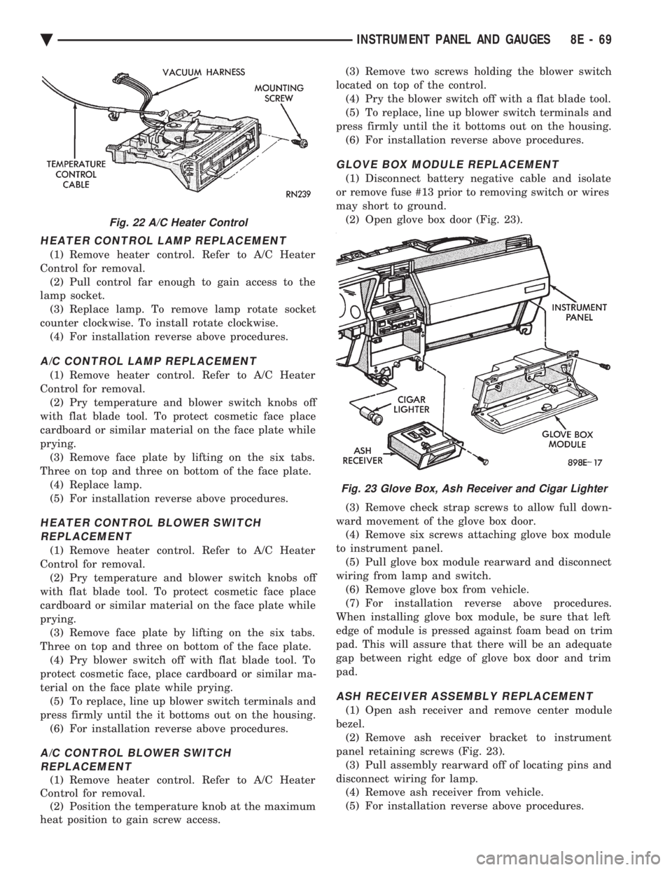
HEATER CONTROL LAMP REPLACEMENT
(1) Remove heater control. Refer to A/C Heater
Control for removal. (2) Pull control far enough to gain access to the
lamp socket. (3) Replace lamp. To remove lamp rotate socket
counter clockwise. To install rotate clockwise. (4) For installation reverse above procedures.
A/C CONTROL LAMP REPLACEMENT
(1) Remove heater control. Refer to A/C Heater
Control for removal. (2) Pry temperature and blower switch knobs off
with flat blade tool. To protect cosmetic face place
cardboard or similar material on the face plate while
prying. (3) Remove face plate by lifting on the six tabs.
Three on top and three on bottom of the face plate. (4) Replace lamp.
(5) For installation reverse above procedures.
HEATER CONTROL BLOWER SWITCHREPLACEMENT
(1) Remove heater control. Refer to A/C Heater
Control for removal. (2) Pry temperature and blower switch knobs off
with flat blade tool. To protect cosmetic face place
cardboard or similar material on the face plate while
prying. (3) Remove face plate by lifting on the six tabs.
Three on top and three on bottom of the face plate. (4) Pry blower switch off with flat blade tool. To
protect cosmetic face, place cardboard or similar ma-
terial on the face plate while prying. (5) To replace, line up blower switch terminals and
press firmly until the it bottoms out on the housing. (6) For installation reverse above procedures.
A/C CONTROL BLOWER SWITCHREPLACEMENT
(1) Remove heater control. Refer to A/C Heater
Control for removal. (2) Position the temperature knob at the maximum
heat position to gain screw access. (3) Remove two screws holding the blower switch
located on top of the control. (4) Pry the blower switch off with a flat blade tool.
(5) To replace, line up blower switch terminals and
press firmly until the it bottoms out on the housing. (6) For installation reverse above procedures.
GLOVE BOX MODULE REPLACEMENT
(1) Disconnect battery negative cable and isolate
or remove fuse #13 prior to removing switch or wires
may short to ground. (2) Open glove box door (Fig. 23).
(3) Remove check strap screws to allow full down-
ward movement of the glove box door. (4) Remove six screws attaching glove box module
to instrument panel. (5) Pull glove box module rearward and disconnect
wiring from lamp and switch. (6) Remove glove box from vehicle.
(7) For installation reverse above procedures.
When installing glove box module, be sure that left
edge of module is pressed against foam bead on trim
pad. This will assure that there will be an adequate
gap between right edge of glove box door and trim
pad.
ASH RECEIVER ASSEMBLY REPLACEMENT
(1) Open ash receiver and remove center module
bezel. (2) Remove ash receiver bracket to instrument
panel retaining screws (Fig. 23). (3) Pull assembly rearward off of locating pins and
disconnect wiring for lamp. (4) Remove ash receiver from vehicle.
(5) For installation reverse above procedures.
Fig. 22 A/C Heater Control
Fig. 23 Glove Box, Ash Receiver and Cigar Lighter
Ä INSTRUMENT PANEL AND GAUGES 8E - 69
Page 562 of 2438
CIGAR LIGHTER REPLACEMENT
(1) Remove center bezel assembly (Fig. 23).
(2) Remove center module lower cover or open for-
ward console lid. (3) Unscrew lighter receptacle shell from recepta-
cle and remove from base instrument panel. (4) Disconnect wiring connectors from lighter re-
ceptacle and remove from vehicle. (5) For installation reverse above procedures.
REAR WINDOW DEFOGGER AND/OR FOG LAMP SWITCH REPLACEMENT
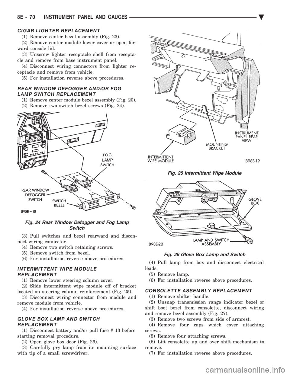
(1) Remove center module bezel assembly (Fig. 20).
(2) Remove two switch bezel screws (Fig. 24).
(3) Pull switches and bezel rearward and discon-
nect wiring connector. (4) Remove two switch retaining screws.
(5) Remove switch from bezel.
(6) For installation reverse above procedures.
INTERMITTENT WIPE MODULE REPLACEMENT
(1) Remove lower steering column cover.
(2) Slide intermittent wipe module off of bracket
located on steering column reinforcement (Fig. 25). (3) Disconnect wiring connector from module and
remove module from vehicle. (4) For installation reverse above procedures.
GLOVE BOX LAMP AND SWITCHREPLACEMENT
(1) Disconnect battery and/or pull fuse # 13 before
starting removal procedure. (2) Open glove box door (Fig. 26).
(3) Carefully pry lamp from its mounting surface
with tip of a small screwdriver. (4) Pull lamp from box and disconnect electrical
leads. (5) Remove lamp.
(6) For installation reverse above procedures.
CONSOLETTE ASSEMBLY REPLACEMENT
(1) Remove shifter handle.
(2) Unsnap transmission range indicator bezel or
shift boot bezel from consolette, disconnect wiring
and remove bezel assembly (Fig. 27). (3) Remove two screws from side of armrest.
(4) Remove four caps which cover attaching
screws. (5) Remove four attaching screws.
(6) Lift consolette up and over shift mechanism to
remove. (7) For installation reverse above procedures.
Fig. 24 Rear Window Defogger and Fog Lamp Switch
Fig. 25 Intermittent Wipe Module
Fig. 26 Glove Box Lamp and Switch
8E - 70 INSTRUMENT PANEL AND GAUGES Ä
Page 595 of 2438
² If no short to ground at connector, check speaker
resistance at amplifier connector for an reading of
three to five ohms.
² If resistance is OK, refer to Radio Diagnosis. If ra-
dio checks OK, replace amplifier.
² If resistance is less than three ohms check
speaker. Check across the speaker connector if less
than three ohms replace speaker. If resistance is OK
repair wires
CONDITION: MECHANICAL NOISE DISTORTION
² Check trim for loose parts and speaker attach-
ments for buzzes
² Remove speaker still connected and listen for dis-
tortion. Distortion replace speaker.
CONDITION: ONE SPEAKER NON-OPERATIVE
² Remove output signal connector from amplifier
and check for three to five ohms resistance to the
non-operative speaker. Refer to Fig. 34 for the appro-
priate pin numbers.
² If resistance is less than three ohms, test speaker
for resistance.
² If OK repair wire. If not replace speaker.
CONDITION: ALL SPEAKERS NON-OPERATIVE
²Check radio for being ON, are the display lights
on
² Radio not ON, refer to Radio Diagnosis
² Check Amplifier Connectors and wires for proper
connection
² Check pin 9 and pin 27 for battery voltage
² If voltage OK replace amplifier ²
If pin 27 has battery voltage and pin 9 has 0 volt-
age. Refer to Power Antenna Diagnosis and test volt-
age at antenna relay.
² If pin 9 has battery voltage and pin 27 has 0 volt-
age. Check pin 27 for short to ground.
² If shorted to ground repair wire
² If no short to ground check fuse cavity number 16
for blown fuse.
² If fuse blows again replace amplifier
RELAY/CHOKEÐINFINITY SPEAKER
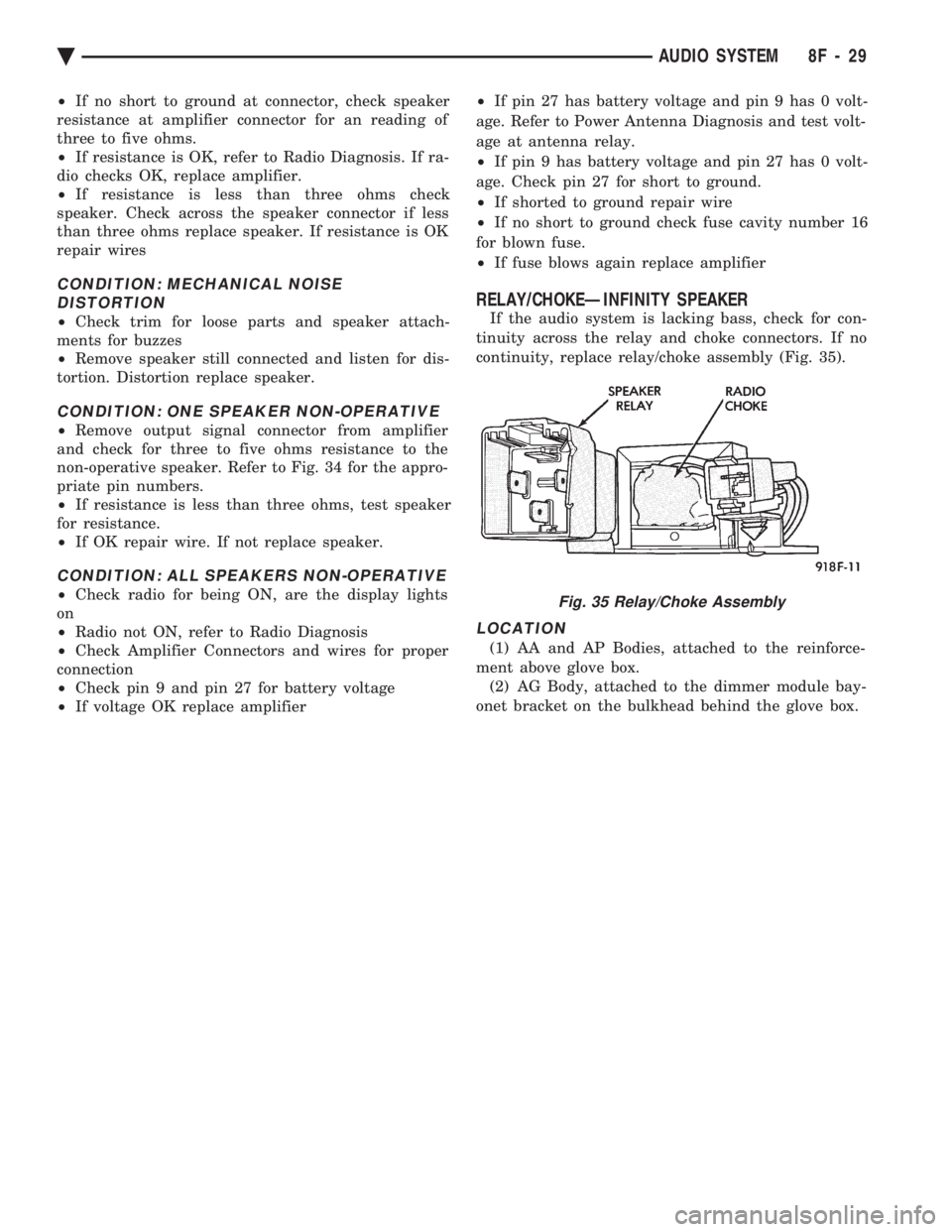
If the audio system is lacking bass, check for con-
tinuity across the relay and choke connectors. If no
continuity, replace relay/choke assembly (Fig. 35).
LOCATION
(1) AA and AP Bodies, attached to the reinforce-
ment above glove box. (2) AG Body, attached to the dimmer module bay-
onet bracket on the bulkhead behind the glove box.
Fig. 35 Relay/Choke Assembly
Ä AUDIO SYSTEM 8F - 29
Page 597 of 2438
HORNS
CONTENTS
page page
GENERAL INFORMATION .................. 1
HORN SWITCH REPLACEMENT ............ 3 TESTING HORN SYSTEM
................. 1
GENERAL INFORMATION
WARNING: ON VEHICLES EQUIPPED WITH AIR
BAG, SEE GROUP 8M, RESTRAINT SYSTEMS FOR
STEERING WHEEL OR COLUMN REMOVAL PROCE-
DURES.
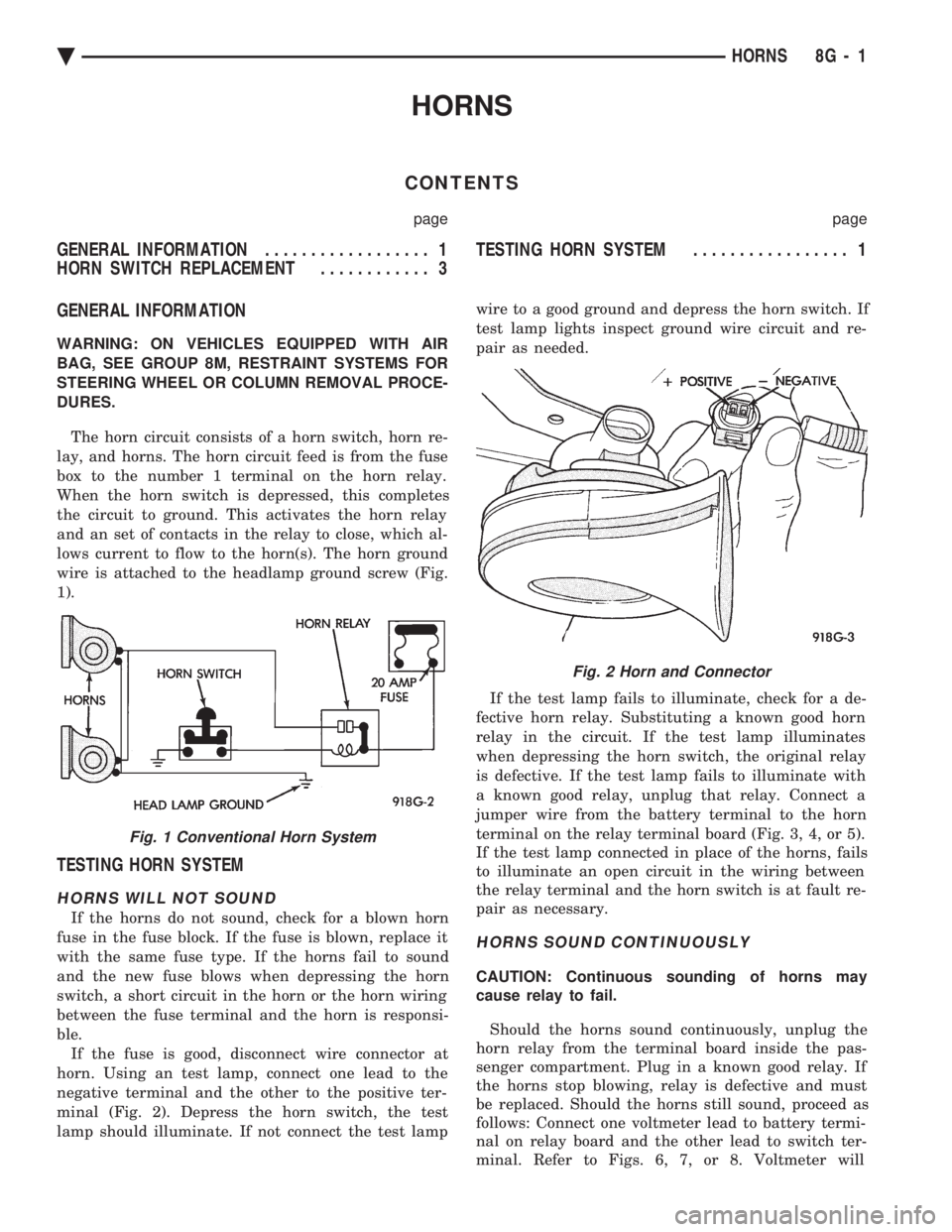
The horn circuit consists of a horn switch, horn re-
lay, and horns. The horn circuit feed is from the fuse
box to the number 1 terminal on the horn relay.
When the horn switch is depressed, this completes
the circuit to ground. This activates the horn relay
and an set of contacts in the relay to close, which al-
lows current to flow to the horn(s). The horn ground
wire is attached to the headlamp ground screw (Fig.
1).
TESTING HORN SYSTEM
HORNS WILL NOT SOUND
If the horns do not sound, check for a blown horn
fuse in the fuse block. If the fuse is blown, replace it
with the same fuse type. If the horns fail to sound
and the new fuse blows when depressing the horn
switch, a short circuit in the horn or the horn wiring
between the fuse terminal and the horn is responsi-
ble. If the fuse is good, disconnect wire connector at
horn. Using an test lamp, connect one lead to the
negative terminal and the other to the positive ter-
minal (Fig. 2). Depress the horn switch, the test
lamp should illuminate. If not connect the test lamp wire to a good ground and depress the horn switch. If
test lamp lights inspect ground wire circuit and re-
pair as needed.
If the test lamp fails to illuminate, check for a de-
fective horn relay. Substituting a known good horn
relay in the circuit. If the test lamp illuminates
when depressing the horn switch, the original relay
is defective. If the test lamp fails to illuminate with
a known good relay, unplug that relay. Connect a
jumper wire from the battery terminal to the horn
terminal on the relay terminal board (Fig. 3, 4, or 5).
If the test lamp connected in place of the horns, fails
to illuminate an open circuit in the wiring between
the relay terminal and the horn switch is at fault re-
pair as necessary.
HORNS SOUND CONTINUOUSLY
CAUTION: Continuous sounding of horns may
cause relay to fail.
Should the horns sound continuously, unplug the
horn relay from the terminal board inside the pas-
senger compartment. Plug in a known good relay. If
the horns stop blowing, relay is defective and must
be replaced. Should the horns still sound, proceed as
follows: Connect one voltmeter lead to battery termi-
nal on relay board and the other lead to switch ter-
minal. Refer to Figs. 6, 7, or 8. Voltmeter will
Fig. 1 Conventional Horn System
Fig. 2 Horn and Connector
Ä HORNS 8G - 1
Page 700 of 2438
(1) Be sure that the module has a battery feed
from the 20 Amp breaker in cavity 1 of the black
connector. Also affected would be the optical horn
and the stop lamps. (2) Be sure that the module has an ignition feed
from 5 Amp fuse in cavity 8 of the black connector.
Also affected would be the body computer, instru-
ment cluster and message center. (3) Be sure that the module has a ground from the
right side cowl behind the body computer to the cav-
ity 5 of the black connector. (4) Be sure that you are supplying a good ground
to the programming wire. (5) If the above circuits are good, replace the Re-
ceiver Module. CONDITION: Doors can be locked or unlocked with
the Keyless Entry transmitter. But the doors will not
lock. The Vehicle Theft Alarm system will not arm,
when using only the power door LOCK switch in the
driver's door. (1) Be sure you have not left key in the ignition
column lock cylinder. (2) If step 1 is OK, check the Key in Lock switch
circuit in the steering column for a short to ground. (3) In this problem the body computer controls the
LOCK function. Be sure that it is providing a battery
voltage output to the door lock relay. The door lock
relay controls the door lock motors. CONDITION: Doors will lock but Vehicle Theft
System will not arm when using the transmitter. (1) The Keyless Entry Receiver Module controls
the door lock signal to the door lock relay. The door
lock relay controls the door lock motors. Check for
battery voltage at cavity 10 of the Theft Alarm mod-
ule from the Receiver module. (2) If voltage is OK, replace Receiver module.
CONDITION: All doors except driver's door will
lock with the transmitter. (1) Test the driver's door output of the Receiver
Module for a ground. (2) If there is no ground at the pin, replace the Re-
ceiver module. (3) If there is a ground at the output, replace the
door lock motor. CONDITION: Only driver's door will lock with the
transmitter.
² Repair ground circuit to unlock relay
² Replace unlock relay
CONDITION: Doors do not lock with the transmit-
ter, but still get horn CHIRP that indicates that they
did lock. Replace Receiver module. CONDITION: Doors will lock with the transmitter
but there is no horn CHIRP. (1) Press horn button, listen horn sound.
(2) If the horn sounded, change horn relay. (3) Still no CHIRP, check continuity between the
horn relay and the receiver output pin. Repair as
necessary. (4) Still no horn CHIRP, replace the receiver mod-
ule. (5) If using a DRB II, refer to Body Diagnostic Pro-
cedures.
REMOTE KEYLESS MODULE REPLACEMENT
(1) Remove lower right instrument panel silencer.
(2) Remove glove box assembly.
(3) Remove three screws attaching the mounting
bracket to instrument panel. (4) Lower bracket and module assembly, to discon-
nect wire connector. (5) Remove two screws attaching the Remote Key-
less entry Module to bracket. (6) Remove two screws attaching the security mod-
ule to bracket. (7) To installation reverse above procedures.
LAMP OUTAGE MODULE REPLACEMENT
(1) Remove lower right instrument panel silencer.
(2) Remove glove box and ash receiver module.
(3) Remove three screws attaching the mounting
bracket to instrument panel. (4) Lower bracket and module assembly, to discon-
nect wire connectors. (5) Remove two screws attaching the Lamp Outage
Module to bracket. (6) Remove two screws attaching the security mod-
ule to bracket. (7) To installation reverse above procedures.
DOOR LOCK INHIBIT
The power door lock inhibit system prevents the
doors from being locked using the power door locks
when either of two conditions occur: (1) The key is in the ignition switch and any of the
doors are open. The ignition switch does not have to
be ON. (2) The key is in the ignition switch and the head-
lamp are on.
AC, AG, AJ AND AY BODIES
With the ignition switch in the ON or OFF position
and the driver's door open the Body Controller will
ignore the command to lock the power door locks.
Once the key is removed, or the driver's door is
closed, the Body Controller will allow the power door
locks to lock. Refer to Body Diagnostic Procedure
Manual for further testing procedures.
8P - 6 POWER LOCKS Ä
Page 702 of 2438
AA BODY
Uses a power door lock inhibit relay. The relay is
located above the glove box compartment.
INHIBIT RELAY
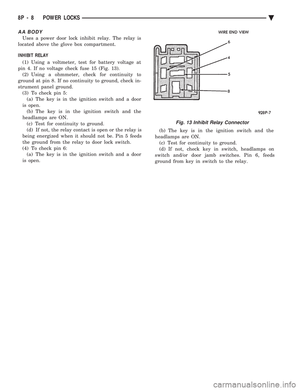
(1) Using a voltmeter, test for battery voltage at
pin 4. If no voltage check fuse 15 (Fig. 13). (2) Using a ohmmeter, check for continuity to
ground at pin 8. If no continuity to ground, check in-
strument panel ground. (3) To check pin 5:(a) The key is in the ignition switch and a door
is open. (b) The key is in the ignition switch and the
headlamps are ON. (c) Test for continuity to ground.
(d) If not, the relay contact is open or the relay is
being energized when it should not be. Pin 5 feeds
the ground from the relay to door lock switch.
(4) To check pin 6: (a) The key is in the ignition switch and a door
is open. (b) The key is in the ignition switch and the
headlamps are ON. (c) Test for continuity to ground.
(d) If not, check key in switch, headlamps on
switch and/or door jamb switches. Pin 6, feeds
ground from key in switch to the relay.
Fig. 13 Inhibit Relay Connector
8P - 8 POWER LOCKS Ä