1993 CHEVROLET DYNASTY oil temperature
[x] Cancel search: oil temperaturePage 2352 of 2438
WARNING: AVOID RADIATOR/CONDENSER FAN
BLADES WHEN WORKING IN THE RADIATOR
AREA. FAN IS CONTROLLED BY TEMPERATURE
AND CAN START ANY TIME IGNITION IS ON. PER-
SONAL INJURY CAN RESULT.
(1) Disconnect fan control switch wire connector.
(2) Using a suitable jumper wire, jump across ter-
minals in wire connector. (3) Connect a suitable continuity tester across fan
control switch terminals. (4) Start engine and set idle at 1300 rpm. The ra-
diator fan should run constantly. (5) Set the A/C controls to A/C and high blower.
(6) If the high pressure gauge reads below 1102
kPa (160 psi) there should be no continuity across
the switch terminals.
CAUTION: Do not allow engine to overheat when ra-
diator air flow is blocked.
(7) Block radiator air flow with a suitable cover to
increase the high side pressure to at least 1585 kPa
(230 psi). Electrical continuity should be detected
across the fan control switch terminals. (8) Remove cover from front of vehicle to allow
high side pressure to decrease. When pressure drops
below 1102 kPa (160 psi), continuity should cease. If fan control switch is defective, replace it.
REMOVAL AND INSTALLATION
CAUTION: Refrigerant removal is not necessary
when removing the Condenser Fan Control Switch.
However, a small amount of refrigerant will vent
from the switch port. Review the refrigerant han-
dling section of Safety Precautions and Warnings in
the General Information section of this Group.
(1) Disconnect wire connector from condenser fan
control switch. (2) Loosen and quickly rotate the switch counter-
clockwise and separate from the high pressure line
switch port. To install, reverse the preceding operation.
DIFFERENTIAL PRESSURE CUT-OUT SWITCH
DIAGNOSIS
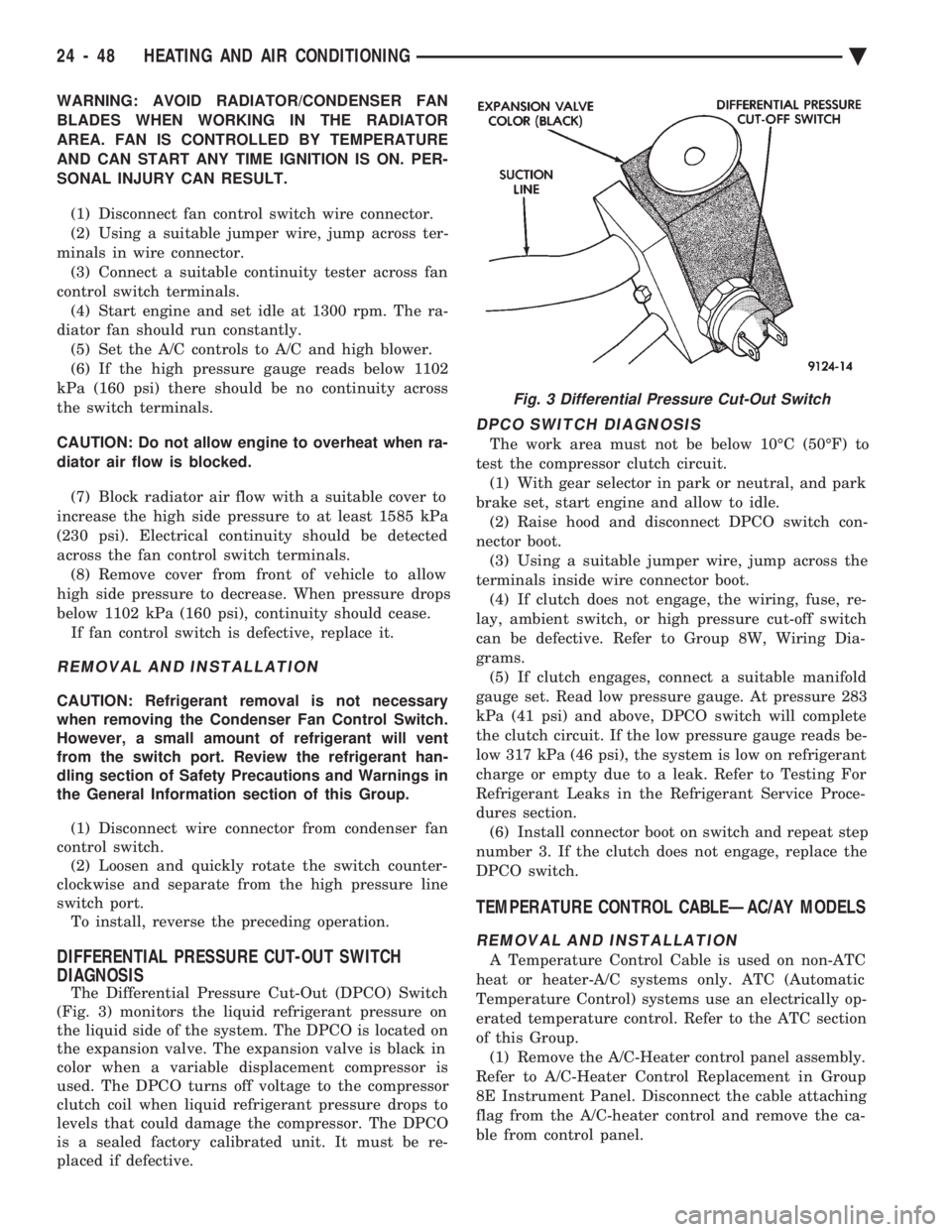
The Differential Pressure Cut-Out (DPCO) Switch
(Fig. 3) monitors the liquid refrigerant pressure on
the liquid side of the system. The DPCO is located on
the expansion valve. The expansion valve is black in
color when a variable displacement compressor is
used. The DPCO turns off voltage to the compressor
clutch coil when liquid refrigerant pressure drops to
levels that could damage the compressor. The DPCO
is a sealed factory calibrated unit. It must be re-
placed if defective.
DPCO SWITCH DIAGNOSIS
The work area must not be below 10ÉC (50ÉF) to
test the compressor clutch circuit. (1) With gear selector in park or neutral, and park
brake set, start engine and allow to idle. (2) Raise hood and disconnect DPCO switch con-
nector boot. (3) Using a suitable jumper wire, jump across the
terminals inside wire connector boot. (4) If clutch does not engage, the wiring, fuse, re-
lay, ambient switch, or high pressure cut-off switch
can be defective. Refer to Group 8W, Wiring Dia-
grams. (5) If clutch engages, connect a suitable manifold
gauge set. Read low pressure gauge. At pressure 283
kPa (41 psi) and above, DPCO switch will complete
the clutch circuit. If the low pressure gauge reads be-
low 317 kPa (46 psi), the system is low on refrigerant
charge or empty due to a leak. Refer to Testing For
Refrigerant Leaks in the Refrigerant Service Proce-
dures section. (6) Install connector boot on switch and repeat step
number 3. If the clutch does not engage, replace the
DPCO switch.
TEMPERATURE CONTROL CABLEÐAC/AY MODELS
REMOVAL AND INSTALLATION
A Temperature Control Cable is used on non-ATC
heat or heater-A/C systems only. ATC (Automatic
Temperature Control) systems use an electrically op-
erated temperature control. Refer to the ATC section
of this Group. (1) Remove the A/C-Heater control panel assembly.
Refer to A/C-Heater Control Replacement in Group
8E Instrument Panel. Disconnect the cable attaching
flag from the A/C-heater control and remove the ca-
ble from control panel.
Fig. 3 Differential Pressure Cut-Out Switch
24 - 48 HEATING AND AIR CONDITIONING Ä
Page 2353 of 2438
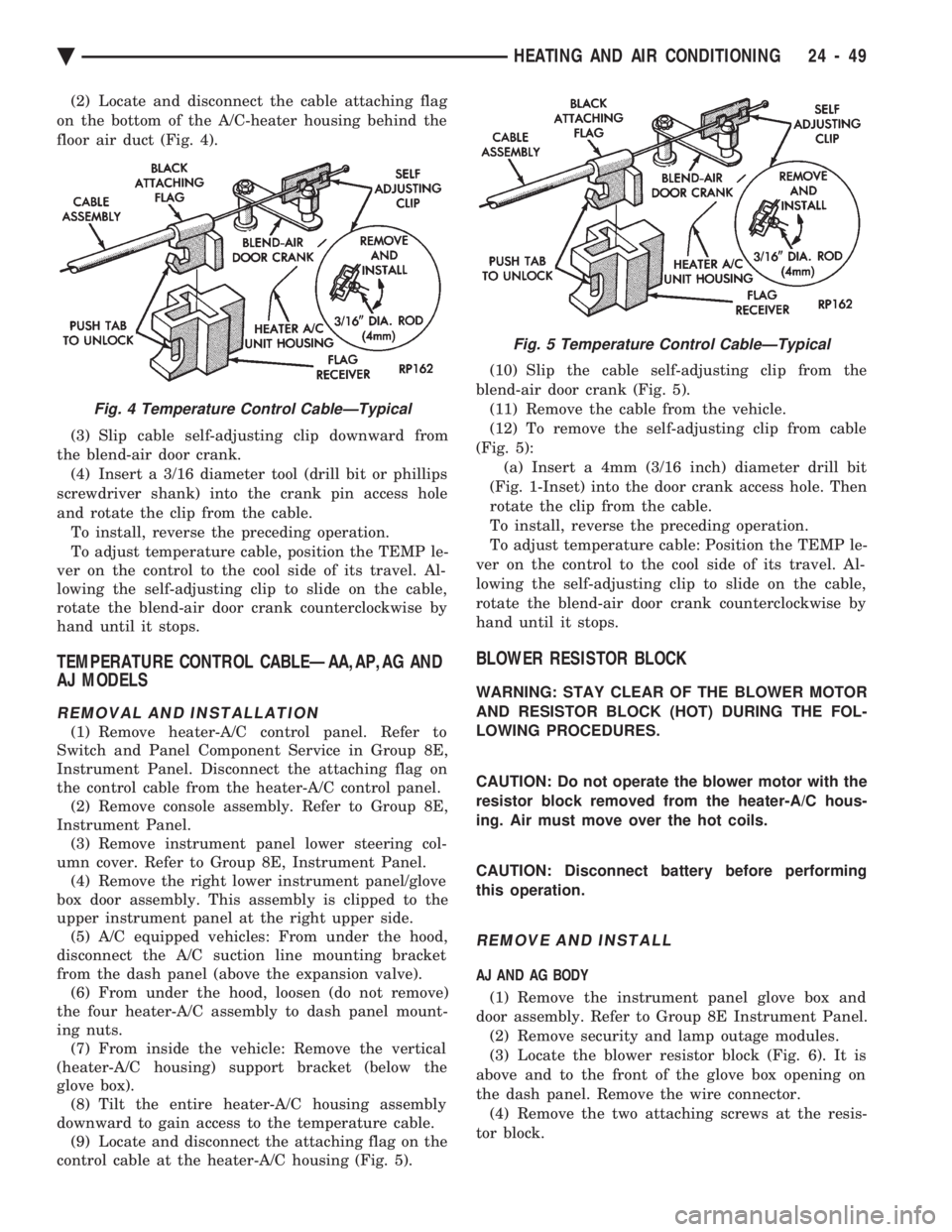
(2) Locate and disconnect the cable attaching flag
on the bottom of the A/C-heater housing behind the
floor air duct (Fig. 4).
(3) Slip cable self-adjusting clip downward from
the blend-air door crank. (4) Insert a 3/16 diameter tool (drill bit or phillips
screwdriver shank) into the crank pin access hole
and rotate the clip from the cable. To install, reverse the preceding operation.
To adjust temperature cable, position the TEMP le-
ver on the control to the cool side of its travel. Al-
lowing the self-adjusting clip to slide on the cable,
rotate the blend-air door crank counterclockwise by
hand until it stops.
TEMPERATURE CONTROL CABLEÐAA,AP,AG AND
AJ MODELS
REMOVAL AND INSTALLATION
(1) Remove heater-A/C control panel. Refer to
Switch and Panel Component Service in Group 8E,
Instrument Panel. Disconnect the attaching flag on
the control cable from the heater-A/C control panel. (2) Remove console assembly. Refer to Group 8E,
Instrument Panel. (3) Remove instrument panel lower steering col-
umn cover. Refer to Group 8E, Instrument Panel. (4) Remove the right lower instrument panel/glove
box door assembly. This assembly is clipped to the
upper instrument panel at the right upper side. (5) A/C equipped vehicles: From under the hood,
disconnect the A/C suction line mounting bracket
from the dash panel (above the expansion valve). (6) From under the hood, loosen (do not remove)
the four heater-A/C assembly to dash panel mount-
ing nuts. (7) From inside the vehicle: Remove the vertical
(heater-A/C housing) support bracket (below the
glove box). (8) Tilt the entire heater-A/C housing assembly
downward to gain access to the temperature cable. (9) Locate and disconnect the attaching flag on the
control cable at the heater-A/C housing (Fig. 5). (10) Slip the cable self-adjusting clip from the
blend-air door crank (Fig. 5). (11) Remove the cable from the vehicle.
(12) To remove the self-adjusting clip from cable
(Fig. 5): (a) Insert a 4mm (3/16 inch) diameter drill bit
(Fig. 1-Inset) into the door crank access hole. Then
rotate the clip from the cable.
To install, reverse the preceding operation.
To adjust temperature cable: Position the TEMP le-
ver on the control to the cool side of its travel. Al-
lowing the self-adjusting clip to slide on the cable,
rotate the blend-air door crank counterclockwise by
hand until it stops.
BLOWER RESISTOR BLOCK
WARNING: STAY CLEAR OF THE BLOWER MOTOR
AND RESISTOR BLOCK (HOT) DURING THE FOL-
LOWING PROCEDURES.
CAUTION: Do not operate the blower motor with the
resistor block removed from the heater-A/C hous-
ing. Air must move over the hot coils.
CAUTION: Disconnect battery before performing
this operation.
REMOVE AND INSTALL
AJ AND AG BODY
(1) Remove the instrument panel glove box and
door assembly. Refer to Group 8E Instrument Panel. (2) Remove security and lamp outage modules.
(3) Locate the blower resistor block (Fig. 6). It is
above and to the front of the glove box opening on
the dash panel. Remove the wire connector. (4) Remove the two attaching screws at the resis-
tor block.
Fig. 4 Temperature Control CableÐTypical
Fig. 5 Temperature Control CableÐTypical
Ä HEATING AND AIR CONDITIONING 24 - 49
Page 2358 of 2438
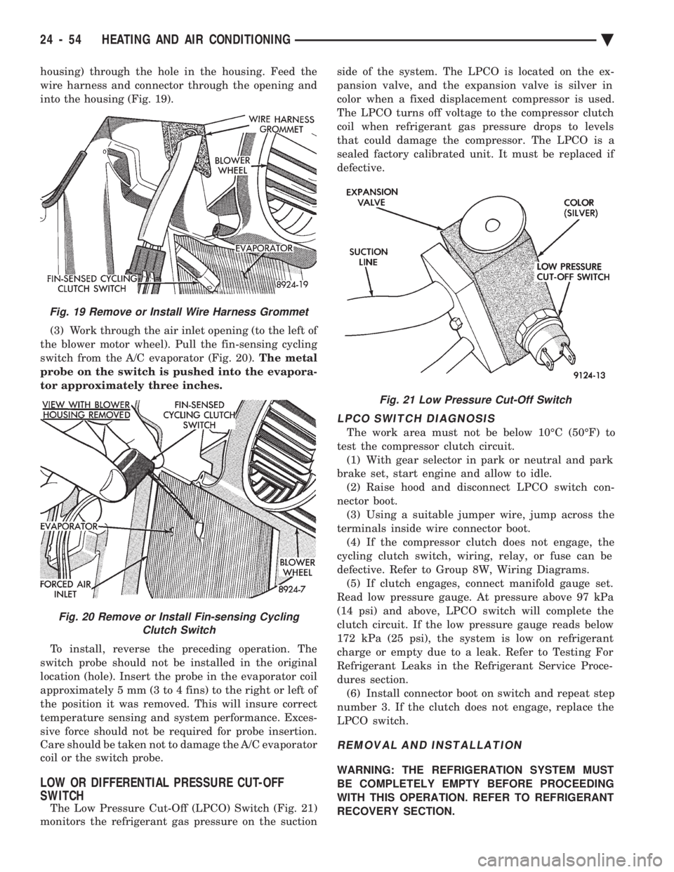
housing) through the hole in the housing. Feed the
wire harness and connector through the opening and
into the housing (Fig. 19). (3) Work through the air inlet opening (to the left of
the blower motor wheel). Pull the fin-sensing cycling
switch from the A/C evaporator (Fig. 20). The metal
probe on the switch is pushed into the evapora-
tor approximately three inches.
To install, reverse the preceding operation. The
switch probe should not be installed in the original
location (hole). Insert the probe in the evaporator coil
approximately 5 mm (3 to 4 fins) to the right or left of
the position it was removed. This will insure correct
temperature sensing and system performance. Exces-
sive force should not be required for probe insertion.
Care should be taken not to damage the A/C evaporator
coil or the switch probe.
LOW OR DIFFERENTIAL PRESSURE CUT-OFF
SWITCH
The Low Pressure Cut-Off (LPCO) Switch (Fig. 21)
monitors the refrigerant gas pressure on the suction side of the system. The LPCO is located on the ex-
pansion valve, and the expansion valve is silver in
color when a fixed displacement compressor is used.
The LPCO turns off voltage to the compressor clutch
coil when refrigerant gas pressure drops to levels
that could damage the compressor. The LPCO is a
sealed factory calibrated unit. It must be replaced if
defective.
LPCO SWITCH DIAGNOSIS
The work area must not be below 10ÉC (50ÉF) to
test the compressor clutch circuit. (1) With gear selector in park or neutral and park
brake set, start engine and allow to idle. (2) Raise hood and disconnect LPCO switch con-
nector boot. (3) Using a suitable jumper wire, jump across the
terminals inside wire connector boot. (4) If the compressor clutch does not engage, the
cycling clutch switch, wiring, relay, or fuse can be
defective. Refer to Group 8W, Wiring Diagrams. (5) If clutch engages, connect manifold gauge set.
Read low pressure gauge. At pressure above 97 kPa
(14 psi) and above, LPCO switch will complete the
clutch circuit. If the low pressure gauge reads below
172 kPa (25 psi), the system is low on refrigerant
charge or empty due to a leak. Refer to Testing For
Refrigerant Leaks in the Refrigerant Service Proce-
dures section. (6) Install connector boot on switch and repeat step
number 3. If the clutch does not engage, replace the
LPCO switch.
REMOVAL AND INSTALLATION
WARNING: THE REFRIGERATION SYSTEM MUST
BE COMPLETELY EMPTY BEFORE PROCEEDING
WITH THIS OPERATION. REFER TO REFRIGERANT
RECOVERY SECTION.
Fig. 21 Low Pressure Cut-Off Switch
Fig. 19 Remove or Install Wire Harness Grommet
Fig. 20 Remove or Install Fin-sensing Cycling Clutch Switch
24 - 54 HEATING AND AIR CONDITIONING Ä