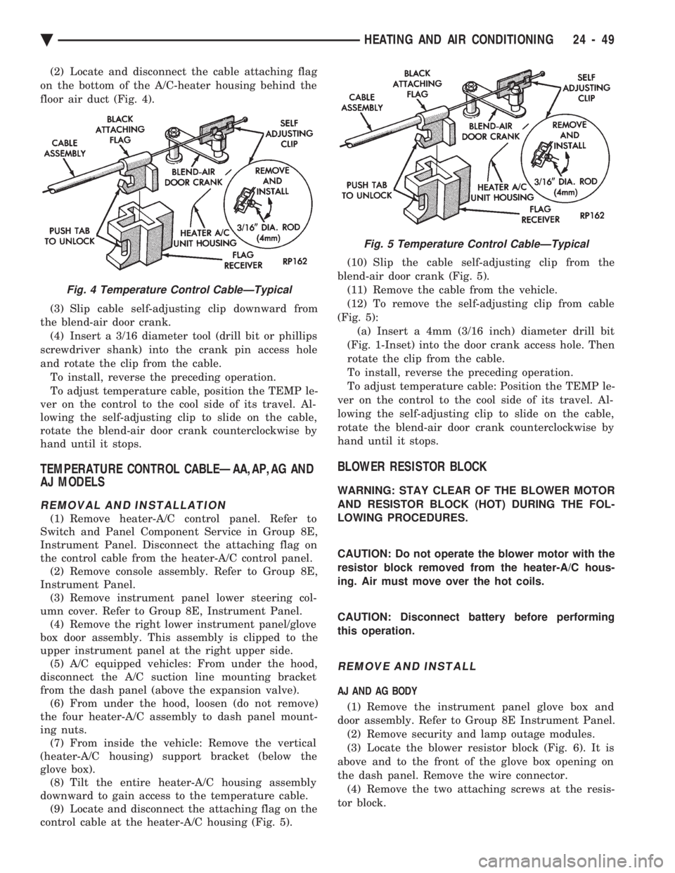
(2) Locate and disconnect the cable attaching flag
on the bottom of the A/C-heater housing behind the
floor air duct (Fig. 4).
(3) Slip cable self-adjusting clip downward from
the blend-air door crank. (4) Insert a 3/16 diameter tool (drill bit or phillips
screwdriver shank) into the crank pin access hole
and rotate the clip from the cable. To install, reverse the preceding operation.
To adjust temperature cable, position the TEMP le-
ver on the control to the cool side of its travel. Al-
lowing the self-adjusting clip to slide on the cable,
rotate the blend-air door crank counterclockwise by
hand until it stops.
TEMPERATURE CONTROL CABLEÐAA,AP,AG AND
AJ MODELS
REMOVAL AND INSTALLATION
(1) Remove heater-A/C control panel. Refer to
Switch and Panel Component Service in Group 8E,
Instrument Panel. Disconnect the attaching flag on
the control cable from the heater-A/C control panel. (2) Remove console assembly. Refer to Group 8E,
Instrument Panel. (3) Remove instrument panel lower steering col-
umn cover. Refer to Group 8E, Instrument Panel. (4) Remove the right lower instrument panel/glove
box door assembly. This assembly is clipped to the
upper instrument panel at the right upper side. (5) A/C equipped vehicles: From under the hood,
disconnect the A/C suction line mounting bracket
from the dash panel (above the expansion valve). (6) From under the hood, loosen (do not remove)
the four heater-A/C assembly to dash panel mount-
ing nuts. (7) From inside the vehicle: Remove the vertical
(heater-A/C housing) support bracket (below the
glove box). (8) Tilt the entire heater-A/C housing assembly
downward to gain access to the temperature cable. (9) Locate and disconnect the attaching flag on the
control cable at the heater-A/C housing (Fig. 5). (10) Slip the cable self-adjusting clip from the
blend-air door crank (Fig. 5). (11) Remove the cable from the vehicle.
(12) To remove the self-adjusting clip from cable
(Fig. 5): (a) Insert a 4mm (3/16 inch) diameter drill bit
(Fig. 1-Inset) into the door crank access hole. Then
rotate the clip from the cable.
To install, reverse the preceding operation.
To adjust temperature cable: Position the TEMP le-
ver on the control to the cool side of its travel. Al-
lowing the self-adjusting clip to slide on the cable,
rotate the blend-air door crank counterclockwise by
hand until it stops.
BLOWER RESISTOR BLOCK
WARNING: STAY CLEAR OF THE BLOWER MOTOR
AND RESISTOR BLOCK (HOT) DURING THE FOL-
LOWING PROCEDURES.
CAUTION: Do not operate the blower motor with the
resistor block removed from the heater-A/C hous-
ing. Air must move over the hot coils.
CAUTION: Disconnect battery before performing
this operation.
REMOVE AND INSTALL
AJ AND AG BODY
(1) Remove the instrument panel glove box and
door assembly. Refer to Group 8E Instrument Panel. (2) Remove security and lamp outage modules.
(3) Locate the blower resistor block (Fig. 6). It is
above and to the front of the glove box opening on
the dash panel. Remove the wire connector. (4) Remove the two attaching screws at the resis-
tor block.
Fig. 4 Temperature Control CableÐTypical
Fig. 5 Temperature Control CableÐTypical
Ä HEATING AND AIR CONDITIONING 24 - 49
To install, reverse the preceding operation.
VACUUM ACTUATORSÐMODE DOORS
The Vacuum Actuators for the Mode Doors are lo-
cated on the drivers side of heater/AC housing above
the accelerator pedal.
REMOVAL
(1) Remove the instrument panel cover under the
steering column. Refer to Group 8E, Instrument
Panel. Heat/Defrost Actuator:
Remove two screws from bracket. Lift actuator up-
ward and pull out (Fig. 13).
Mode Door Actuator:
Remove two screws from bracket (Fig. 14). Rotate
actuator counter-clockwise to unhook from door and
pull to remove.
INSTALLATION
Heat/Defrost Actuator: Install actuator link through housing and insert in
heat defrost door slot. Push down to hook link to
door. Locate the bracket to the housing and install
two screws. Mode Door Actuator:
Insert the actuator shaft through the hole in the
housing and heat/defrost door. Attach through
mounting hole in the mode door. Install two screws
in bracket. Install the instrument panel cover under the steer-
ing column.
AIR DISTRIBUTION DUCT
REMOVAL AND INSTALLATION
(1) Instrument panel assembly must be removed.
Refer to Group 8E, Instrument Panel. (2) After instrument panel has been removed, sep-
arate the defroster/demister ducts from the air distri-
bution duct. (3) Remove the air distribution duct-to-instrument
panel mounting screws (Fig. 15). To install, reverse removal procedure.
DEFROSTER DUCTS/DEMISTER DUCTS AND
HOSES
REMOVAL AND INSTALLATION
(1) Instrument panel assembly must be removed.
Refer to Group 8E, Instrument Panel. (2) After instrument panel has been removed, sep-
arate the defroster/demister ducts from the air distri-
bution duct. (3) Remove the demister tubes and hoses (Fig. 16).
To install, reverse removal procedure.
Fig. 12 Heater Hose RoutingÐ3.0 L EngineÐTypical
Fig. 13 Removing or Installing Heat/Defrost Vacuum Actuator Assembly
Fig. 14 Mode Door Vacuum Actuators
24 - 52 HEATING AND AIR CONDITIONING Ä