1992 VOLKSWAGEN TRANSPORTER Outlet
[x] Cancel search: OutletPage 57 of 164

Downloaded from www.Manualslib.com manuals search engine
CONTROLS
AND
EQUIPMENT
Heating
and
ventilation
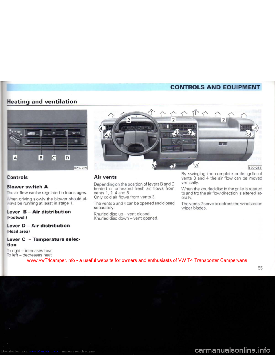
Controls
Blower
switch
A
~~e air flow can be regulated in four stages.
.hen
driving slowly the blower should al-
ays
be running at least in stage 1.
Lever
B - Air
distribution
Footwell)
Lever
D - Air
distribution
Head
area)
Lever
C -
Temperature
selec
tion
To
right - increases heat
~D
left
- decreases heat Air
vents
Depending
on the position of levers B and D
heated
or unheated fresh air flows from
vents 1, 2, 4 and 5.
Only
cold air flows from vents 3.
The
vents 3 and 4 can be opened and closed
separately:
Knurled
disc up - vent
closed.
Knurled
disc down - vent opened.
By
swinging the complete outlet grille of
vents 3 and 4 the air flow can be moved
vertically.
When
the knurled disc in the grille is rotated
to and fro the air flow direction is altered lat
erally.
The
vents 2 serve to defrost the windscreen wiper blades.
55
www.vwT4camper.info - a useful website for owners and enthusiasts of VW T4 Transporter Campervans
Page 59 of 164

Downloaded from www.Manualslib.com manuals search engine
CONTROLS AND
EQUIPMENT
Air
conditioner*
in cab
Description
T".e air conditioner is a combined cooling srd heating system which provides the
r-aximum possible comfort all the year
rcjnd.
Tpe air conditioner works only when the en-
pie
is running and the ambient tempera- t.re is above about + 5 degrees C.
,ien air conditioner is switched on it re-
bjces not only the temperature inside the
•
ehicle but also the air humidity. When the
=-nbient
air humidity is high this not only
Iakes
the vehicle occupants feel more
comfortable but also prevents the windows
""Dm
misting up.
~ne cooling system works best when all the
v.indows are closed.
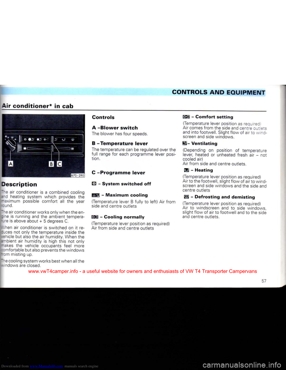
Controls
A
-Blower
switch
The blower has four speeds.
B -
Temperature
lever
The temperature can be regulated over the
full range for each programme lever
posi
tion.
C
-Programme
lever
E] -
System
switched
off -
Maximum
cooling
(Temperature lever B fully to
left)
Air from
side and centre outlets
SSI -
Cooling
normally
(Temperature lever position as required)
Air
from side and centre outlets
SS§i
-
Comfort
setting
(Temperature lever position as requ rez
Air
comes from the side and centre
OJ:
e:s
and into footwell. Slight flow of air to
•:.
-z- screen and side windows.
H-
Ventilating
(Depending on position of temperature
lever, heated or unheated fresh air - not
cooled
air)
Air
from side and centre outlets,
dj -
Heating
(Temperature lever position as required)
Air
to the footwell, slight flow of air to wind screen and side windows and the side and
centre outlets
Wi -
Defrosting
and
demisting
(Temperature lever position as required)
Air
to windscreen and to side windows, slight flow of air to footwell and to the side
and centre outlets.
57
www.vwT4camper.info - a useful website for owners and enthusiasts of VW T4 Transporter Campervans
Page 60 of 164

Downloaded from www.Manualslib.com manuals search engine
CONTROLS
AND EQUIPMENT
Air
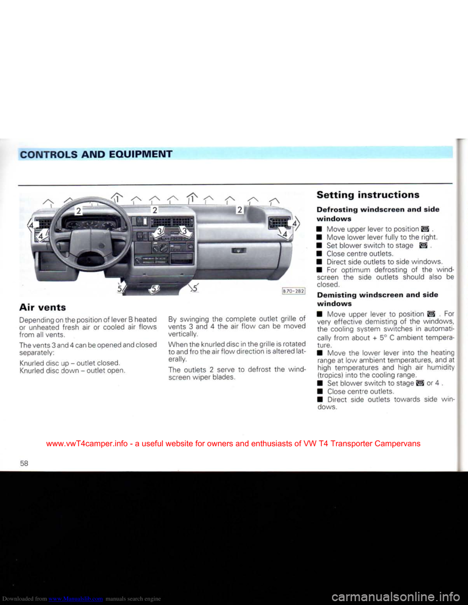
vents
Depending
on the position of lever B heated
or
unheated fresh air or cooled air flows
from all vents.
The
vents 3 and 4 can be opened and closed
separately:
Knurled
disc up - outlet
closed.
Knurled
disc down - outlet open.
By
swinging the complete outlet grille of
vents 3 and 4 the air flow can be moved
vertically.
When
the knurled disc in the grille is rotated
to and fro the air flow direction is altered lat
erally.
The
outlets 2 serve to defrost the wind
screen
wiper blades.
Setting
instructions
Defrosting
windscreen
and side
windows
• Move upper lever to position ES .
• Move lower lever fully to the
right.
• Set blower switch to stage ES , •
Close
centre outlets.
• Direct side outlets to side windows.
• For optimum defrosting of the wind
screen
the side outlets should also be
closed.
Demisting
windscreen
and side
windows
• Move upper lever to position ES . For very effective demisting of the windows,
the cooling system switches in automati
cally
from about + 5° C ambient tempera
ture.
• Move the lower lever into the heating
range
at low ambient temperatures, and at
high temperatures and high air humidity
(tropics) into the cooling range.
• Set blower switch to stage El or 4 .
•
Close
centre outlets.
• Direct side outlets towards side win
dows.
58
www.vwT4camper.info - a useful website for owners and enthusiasts of VW T4 Transporter Campervans
Page 61 of 164

Downloaded from www.Manualslib.com manuals search engine
CONTROLS
AND
EQUIPMENT
Heating
interior
quickly
I Move upper lever to . I Move lower lever fully to the
right.
I Set blower switch to E3 .
I
Close
centre outlets.
I Direct side outlets towards side win-
5:
.vs.
•(eating
interior
comfortably
I Move upper lever to SSi (comfort set 's) or to CS depending on where you
• : jId like the air flow to be.
I Set air temperature as desired
with
: .ver lever.
I Set blower switch to stage 1 or 2.
I Adjust side and centre outlets as re-
:. 'ed. At low ambient temperatures it is
cvisable
to close the centre outlets and di-
ect flow from side outlets towards the side
I ndows. Fresh air
operation
• Move upper lever to
EH
.
• Set air temperature as desired
with
lower lever.
• Set blower switch to desired stage.
• Adjust side and centre outlets as re
quired.
Maximum
cooling
•
Close
all windows. • Move upper lever to •
• Move lower lever fully to
left
or set as re
quired.
• Set blower switch to stage 4.
• Adjust side and centre outlets as re
quired.
However, at least one
outlet
mustal-
ways
be open otherwise the cooling
sys
tem may ice up.
With this setting the air is drawn from inside
the vehicle and cooled (recirculating air operation).
Normal
cooling
• Move upper lever to EM or
ESS*
.
• Set air temperature as desired .-. :~ lower lever.
• Set blower to stage 1 - 4 as desired.
• Adjust side and centre outlets as re
quired.
In position EM at least one
outlet
must always be open otherwise the cooling
system
may ice up.
With this setting ambient air is drawn in and
cooled.
www.vwT4camper.info - a useful website for owners and enthusiasts of VW T4 Transporter Campervans
Page 63 of 164

Downloaded from www.Manualslib.com manuals search engine
CONTROLS AND
EQUIPMENT
Air conditioner* in passenger compartment Recirculating air switch*
th the air conditioner in the passenger
:: apartment the rear seating area can also
:e comfortably cooled down.
air conditioner only functions if the air
:: iditioner in the cab is switched on - see
:;ge 57. However, adjustment of the out-
: can be performed independent of the
I stem in the cab. The control elements are : rated on the dash panel - see illustration.
air throughput can be set in any one of
;: J stages (left hand rotary switch).
Th e temperature infinitely variable with the ::ary control (right hand switch).
I Dckwise - increased cooling output
--ti-clockwise - decreased cooling output Air outlets
The air outlets are located in the roof area
above the rear seats.
The outlets can be closed or opened separ
ately.
By pivoting the outlet grilles the direction of
air flow can also be adjusted.
This switch can be used to change over to recirculating air. This will prevent badiy con-
taminated air from entering the vehicle, e.g.
when driving through a tunnel.
Recirculating air operation should only be
used briefly otherwise the windows wil
mist up.
Switch to left - Recirculating air operation
Switch to right - Fresh air operation
Note
On vehicles with air conditioner a recirculating air switch is located in the bank of
switches in the instrument panel.
www.vwT4camper.info - a useful website for owners and enthusiasts of VW T4 Transporter Campervans
Page 64 of 164

Downloaded from www.Manualslib.com manuals search engine
CONTROLS AND EQUIPMENT
Additional
heater*
With the additional heater the rear seating
area
can also be comfortably heated.
Its blower can be switched on
with
a three
stage
rotary switch in the dash panel
(left
hand illustration).
Temperature regulation is carried out to gether
with
the temperature regulation of
the normal heater - see page 55 .
On
vehicles
with
an airconditionertempera-
ture regulation forthe additional heater is by way of a rotary control on the
right
adjacent
to the blower switch (centre illustration).
Clockwise
- increased heat output
Anti-clockwise
- decreased heat output
On
vehicles
with
seating arrangement the
outlet is located under the centre row of
seats.
This outlet can be closed by pushing it in.
On
the Delivery van, Multivan and Camper
the outlet is located behind the
front
pass
enger's
seat.
62
www.vwT4camper.info - a useful website for owners and enthusiasts of VW T4 Transporter Campervans
Page 65 of 164

Downloaded from www.Manualslib.com manuals search engine
CONTROLS AND EQUIPMENT
Auxiliary
heater*
To
switch heater on
•
Press
rocker switch D on rent.
• Select desired heat
with
knee -
The
green heater in-operatior. =~~" _
comes
on.
Regulating
heat
The
heat is infinitely adjustable
with
:~e knob A.
After heater has been switched on it takes
a
little
time before heat can be
felt.
When
the set temperature is reached, the green in-operation lamp becomes darker.
The
temperature is then held fairly constant by the heater thermostatically.
w-^
=
jxiliary heater works independently of
me .ehicle heating. It is supplied
with
fuel
I: rr the vehicle tank.
He suxiliary heater can be used continu
es
. when on the move or stationary.
|r~? current is supplied from a 2nd battery.
r~T
air flows from the outlets behind the p*.er's seat.
k- the summer the heater blower can be
(sed
to circulate the air in the vehicle with-
it.: heat.
5v. itching on and off and regulating the aux-
tey heater are done from the control panel
r the dash panel.
-
a
timer* is
fitted
(see page 65) the control
panel
is located on the roof cross member I the passenger compartment.
A
BCD
[J70~-T971
Control
elements
A
- Regulating heat output
B
- Overheating indicator (red)
C
- Heater in-operation lamp (green)
D
-
Rocker
switch for switching heater on
and
off and operating blower without heat.
www.vwT4camper.info - a useful website for owners and enthusiasts of VW T4 Transporter Campervans
Page 66 of 164

Downloaded from www.Manualslib.com manuals search engine
CONTROLS
AND EQUIPMENT
To
switch
heater
off
• Move rocker switch D to centre position.
The
heater in-operation lamp C then goes out, but the biower continues to run for a
short time.
Note
The
warning lamp B flashes if the heater
overheats.
If this happens, check whether
the air intake or the warm air outlet are
blocked.
Switching
blower
on
without
heat
Press
rocker switch D on the
left.
The green
in-operation lamp C comes on.
Switching
off
• Move switch D to centre position. The in-operation lamp goes out.
Stipulation is
that
the heater is not being
controlled at the same time by the timer
(see
next page).
Attention
The
heater
must
be
switched
off in enclosed spaces and
when
fil
ling
the
tank.
Notes
• Every time the heater is switched off the blower continues to run for a while to cool
the heater down quicker. When filling tank it is not necessary to wait to end of run-on.
• When driving cross-country or through mud or deep snow the heater exhaust pipe
can
become blocked. Before switching the heater on intheseconditions, check thatthe
pipe is clear. • The
following
official
regulation
is
applicable
in
Germany:
The
heat exchanger of the heater may be
used
for 10 years. After this period the heat
exchanger
must be replaced by a Genuine heat exchanger in a Volkswagen Dealer
ship.
To enable this period of time to be monitored the year when the heater is taken
into use is marked on the maker's plate on
the heater (under vehicle floor).
The
Volkswagen dealer enters the date of
replacement on the plate on the heater.
64
www.vwT4camper.info - a useful website for owners and enthusiasts of VW T4 Transporter Campervans