Page 995 of 1164
AIR CONDITIONER U
Dlsassembly / Assembly
Disassemble and assemble as shown in the figure.
1. Evaporator 2. Expansion valve 3. Thermoswitch
Replacement
Expansion valve
Note
l Before replacement of the expansion valve, care-
fully check the refrigeration system, referring to the
troubleshooting information on page U-14.
1. Remove the cooling unit. (Refer to page U-38.)
2. Disassemble the cooling unit. Remove the evaporator and
expansion valve as an assembly.
3. Disconnect the inlet and outlet pipes.
I 4. Remove the capillary tube from the outlet pipe and remove
23UOUX-024 the expansion valve.
5. Install in the reverse order of removal, noting the following.
Note
l Apply clean compressor oil to the O-rings before
connecting the fittings.
Tightening torque
Inlet pipe:
12-15 N-m (1.2-l .5 m-kg, 8.7-l 1 ft-lb)
Outlet pipe:
29-34 Nmrn (3.0-3.5 m-kg, 22-25 ft-lb)
u-39
Page 1000 of 1164
U AIR CONDITIONER
23UOUX-02
Thermal Protector Replacement
1. Removal of discharge valve body
Remove the bolts and carefully remove the discharge valve
body. .-
2. Removal of snap ring and thermal protector
Note
l When removing the thermal protector, do not pull
the harness wires but push the protector out from
its back side.
23UOUX-028 3. Installation of thermal protector
1) Check that the O-ring groove is free from foreign matter.
Apply compressor oil to the O-ring and properly fit it in
the groove.
2) Before installing the thermal protector, check it for con-
tinuity.
23uoux-029 _/”
THERMAL PROTECTOR
23UOUX-03
TH
PR
3) Install the snap ring so that its chamfered edge side faces
the thermal protector (the non-chamfered side faces out-
ward) as shown left.
Make sure the snap ring is seated securely in its groove.
Note
l Install the thermal protector so that its two lead wire
outlet sections are horizontal as shown left.
Page 1001 of 1164
AIR CONDITIONER U
23UOUX-031 DISCHARGE
VALVE BODY
CYLINDER
1
23UOUX-03
4. Installation of discharge valve body
1) Replace the O-ring and gasket with new ones.
Apply compressor oil to the new O-ring and gasket and
properly assemble them.
Note
l Fit the gasket as shown left while checking that its
top side faces upward.
2) Carefully install the discharge valve body on the com-
pressor and finger tighten the six M6 bolts.
Note
Bolt torquing sequence
l Torque the two socket head bolts (A) to the specifi-
cation.
l Torque the four bolts (B) in a diagonal manner to
the specification.
Tightening torgue: 9.8 N,rn (100 cm-kg, 87 in-lb)
u-45
Page 1009 of 1164

AIR CONDITIONER U
CONDENSER
Removal / Installation
1. Discharge the refrigeration system. (Refer to page U-32.)
2. Remove the radiator grille. (Refer to Section S.)
3. Remove the receiver/drier. (Refer to page U-52.)
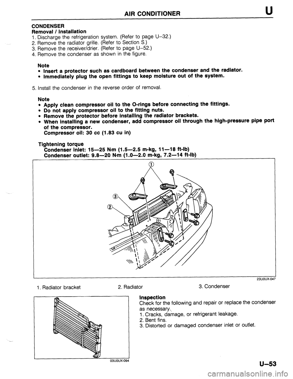
4. Remove the condenser as shown in the figure.
Note
l Insert a protector such as cardboard between the condenser and the radiator.
l Immediately plug the open fittings to keep moisture out of the system.
5. install the condenser in the reverse order of removal.
Note
l Apply clean compressor oil to the O-rings before connecting the fittings.
l Do not apply compressor oil to the fitting nuts.
l Remove the protector before installing the radiator brackets.
l When installing a new condenser, add compressor oil through the high-pressure pipe port
of the compressor.
Compressor oil: 30 cc (1.83 cu in)
Tightening torque
Condenser inlet: 15-25 N*rn (1.5-2.5 m-kg, 11-18 ft-lb)
Condenser outlet: 9.8-20 N#m (1 .O-2.0 m-kg, 7.2-14 ft-lb)
1. Radiator bracket
2. Radiator 3. Condenser
23UOUX-01
Inspection
Check for the following and repair or replace the condenser
as necessary.;
1. Cracks, damage, or refrigerant leakage.
2. Bent fins.
3. Distorted or damaged condenser inlet or outlet.
u-53
Page 1010 of 1164
AIR CONDITIONER
REFRIGERANT LINES
On-vehicle Inspection
Check for leakage at connections. (Refer to page U-32.)
Repair or replace as necessary.
Replacement
1. Discharge the refrigeration system. (Refer to page U-32.)
2. Replace the faulty pipe or hose.
Note
l Immediately plug the open fittings to keep moisture out of the system.
l Apply clean compressor oil to the O-rings before connecting the fittings.
l Do not apply compressor oil to the fitting nuts.
Tightening torque (fittings):
Location Tightening torque
0 9.8-20 N.m
(1.0-2.0 m-kg, 7.2-14 ft-lb)
0 15-25 N-m (1.5-2.5 m-kg, 11-18 ft-lb)
0 9.8-16 N.m (1.0-1.6 m-kg, 7.2-12 ft-lb)
fa 20-29 N.m
(2.0-3.0 m-ka 15-21 ft-lb)
3. Evacuate, charge, and test the refrigeration system.
1. High-pressure hose
2. Low-pressure hose
3. Cooler pipe No.1 4. Cooler pipe No.2 6. Cooler pipe No.4
5. Cooler
pipe No.3 7. Cooler pipe No.5
u-54
Page 1022 of 1164

TECHNICAL DATA
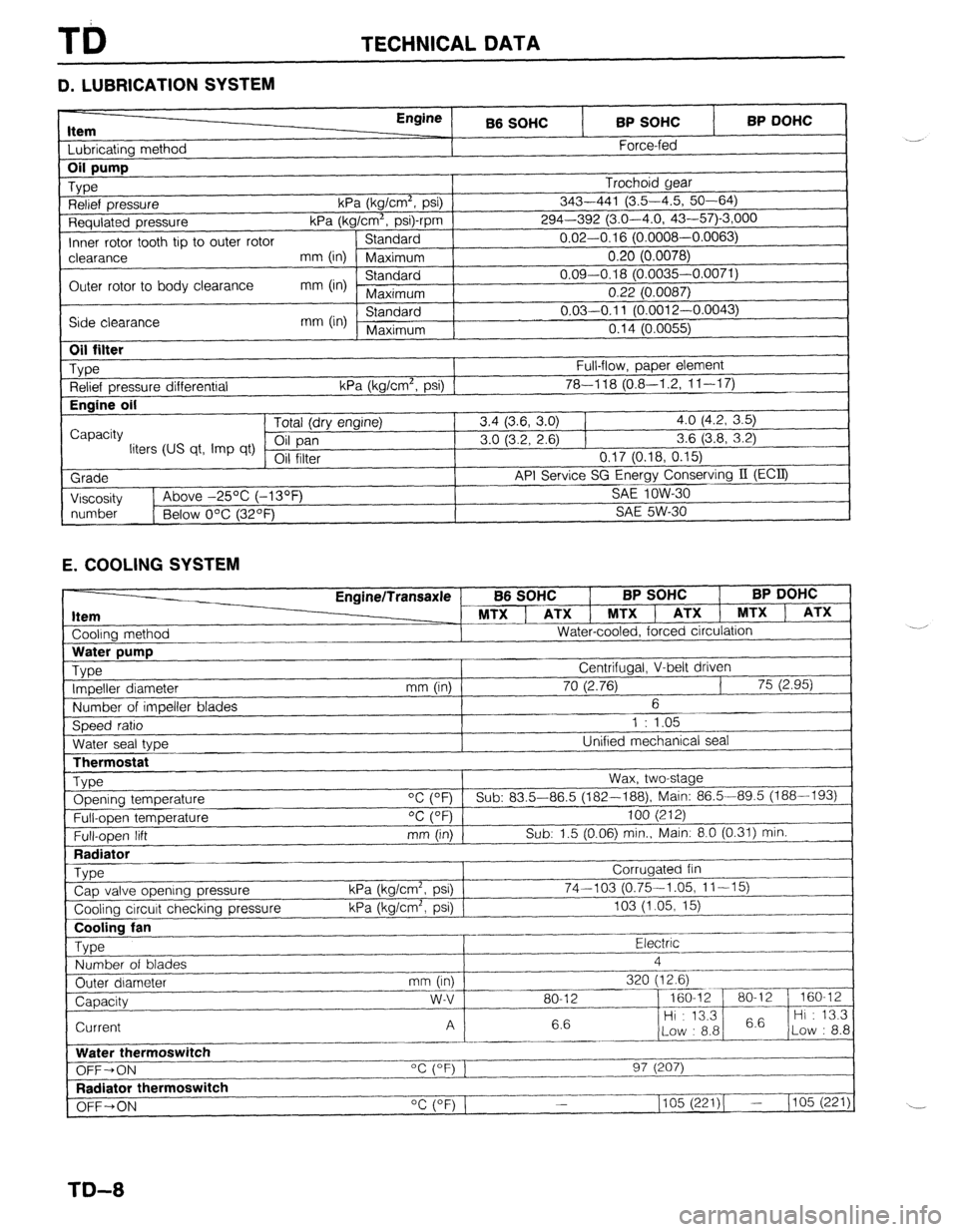
D. LUBRICATION SYSTEM
Item I I bhricatinn mothnd
Engine
B6 SOHC BP SOHC
Force-fed BP DOHC 1
Requlated pressure kPa (kg/Cm”, p
Inner rotor tooth tip to outer rotor Standard
I-‘---- -.----,
clearance mm (in) Maximum 0.20 (0.0078)
Outer rotor to body clearance mm (in) Standard 0.09-0.18 (0.0035-0.0071)
Maximum 0.22 (0.0087)
Side clearance mm (in) Standard 0.03-0.11 (O.pniq n nnn=’
Maximum n4rl ‘-
“” I r-“.““+..I,
I “. I ‘t (U.0055)
I
1
Oil filter
_ Type
Relief pressure differential
Engine oil
I
Capacity
liters (US qt, Imp qt)
Grade
I Viscosity Full-flow, paper element
kPa (kg/cm’, psi) 1 78-l 18 (0.8-I .2, 1 l-l 7) Tntal /An, nnr*inol 3.4 (3.6, 3.0) 1 4.0 (4.2, 3.5)
3.0 (3.2, 2.6) 1 3.6 (3.8, 3.2)
VII 111Lb1 0.17 (0.18, 0.15)
API Service SG Energy Conserving II (ECQ
1
SA!f InW-Xl 1~ Above -25% (-13OF _ .-.. --
I
I
number
1 Below O’C (32OF) SAE 5W-30
1
E. COOLING SYSTEM
Cooling method EnginelTransaxle
MTX ] ATX 1 MTXl
Water-cooled, forced circulation
J B6 SOHC BP SOHC BP DOHC
, ATX 1 MTX ) ATX
LThermostat
Type Opening temperature
Full-open temperature
Full-open lift
Radiator
_ Type
Cap valve opening pressure
Cooling circuit checking pressure Wax, two-stage
“C (OF) Sub: 83.5-86.5 (182--188), Main: 86.5-89.5 (188-193)
OC (OF) 100 (212)
mm (in) Sub: 1.5 (0.06) min., Main: 8.0 (0.31) min.
Corrugated fin
kPa (kg/cm2, psi) 74-103 (0.75-1.05, 11-15)
kPa (kg/cm’, psi) 103 (1.05, 15)
~..
Cooling fan
Type Electric .-
Number of blades 4
_.---- _I___-
Outer diameter mm (in) 320 (12.6)
--_ ~~-
Capacity w-v 80-12 - 160-12 80-l 2 160-12
6.6 Hi : 13.3
6.6 Hi : 13.3
Current A
Low : 8.8 Low : 8.8
_------ ._____
Water thermoswitch
“c (OF) 1
OFF-ON 97 (207)
I--.
Radiator thermoswitch
__-I____-
OFF+ON “C (OF) 1 1105 (221)( - (105 (221)
TD-8
Page 1034 of 1164

TD TECHNICAL DATA
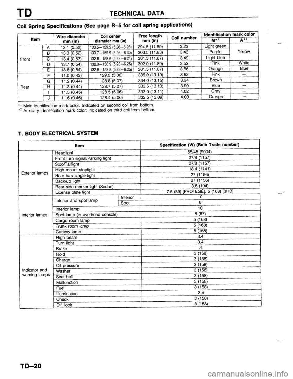
Coil Spring Specifications (See page R-5 for coil spring applications)
*’ Main identification mark color: Indicated on second coil from bottom. l * Auxiliary identification mark color: Indicated on third coil from bottom.
T. BODY ELECTRICAL SYSTEM
Item
Headlight
Frnnt tl wn sinnnl/Pnrkinn linht
Specification (W) (Bulb Trade number)
65145 (9004)
2718 II I 571
I
“‘VW, I u”“y’ 1. I” \’ ‘V’,
uinh mount stoplight 18.4 (1141)
turn single light 27 (1156)
Y-,-~p light 27 (1156)
Rear side marker light (Sedan) 3.8 (194)
License plate light 7.5 (89) [PROTEGE], 5 (168) [3HBl
Interior 10
Interior and spot lamp
spot 6
Interior lamp 10
‘i--” Spot lamp (in overhead console)
8 (67)
Cargo room lamp 5 (168)
Trunk room lamp 5 (168)
I I
ntminr Iamnc
I
Curtesy lamp
High beam
Turn light
Brake
Hold
) Charge 5 (168)
3.4
3.4
3
3 (158)
i
Oil pressure
Washer
Seat belt
Malfunction
Fuel
illumination 3 (158)
3 (158)
3 (158)
3 (158)
3 (158)
3 (158)
3.4 Indicator and
warning lamps
Check 3 (158)
Dif. lock
I 3 (158) .-
,
-.-’
I
I
TD-20
Page 1043 of 1164
SPECIAL TOOLS ST
AUTOMATIC TRANSAXLE (CONT’D)
TOOL NUMBER
& DESCRIPTION PRIORITY ILLUSTRATION
49 0378 400A
Gauge set, A
oil pressure
49 HO19 002
Adapter A
49 6019 008
Leak checker A
FRONT AND REAR AXLES
ILLUSTRATION
49 F027 OAl
49 B026 1AO
Puller, wheel hub
49
MOO5 795
Installer set,
49
FO26 102
hstaller, bearing TOOL NUMBER
& DESCRIPTION
49 GO30 795
Installer, oil seal
49 BO19 002
Body
49 0180 510B
Preload
measuring
attachment PRIORITY
A
A
B
TOOL NUMBER
& DESCRIPTION PR’oRITY
49 VOOl 795
Installer, oil seal
49 F026 103
I
Removing plate
49 GO33 107
Installer,
dust cover
49 HO34 2A0
Lower arm
bushing puller
& installer ILLUSTRATION
ILLUSTRATION
ST-7