1992 MAZDA PROTEGE oil pressure
[x] Cancel search: oil pressurePage 972 of 1164

U TROUBLESHOOTING GUIDE
Case 1: Insufficient refrigerant
Measured pressure
Low-pressure side: Less than 78.5 kPa (0.8 kg/cm2, 11.4 psi)
High-pressure side: 785-883 kPa (8-9 kg/cm2, 114-128 psi)
Condition
l Outlet air from vents not cold.
l Bubbles seen in sight glass.
Step 1
1. Check for oil stains on the pipes, hoses and other parts, (Refer to illustration below.)
2. If oil staining is found at the connection of pipes or hoses, replace the O-ring; then, evacuate, charge,
and test the system.
3. If oil staining is not found, go to Step 2.
05UOUX-02
Step 2
1. Check for leakage from the following connections with a gas leak tester.
l Inlet and outlet of condenser.
l Inlet and outlet of receiver/drier.
l Inlet and outlet of compressor.
l Sight glass.
l Inlet and outlet of cooling unit.
2. If leakage is evident, go to Step 3.
3. If leakage cannot be found, evacuate, charge, and test the system. (System OK, but refrigerant leaked
gradually over time.)
Step 3
1. Check tightening torque of the connection where leak was detected.
2. If the connection is loose, tighten the connection to the specified torque; then evacuate, charge, and test
the system. --
3. If the connection is properly tightened, replace the O-ring; then evacuate, charge, and test the system.
U-16
Page 994 of 1164

U
COOLING UNIT
Removal / Installation AIR CONDITIONER
1. Discharge the refrigeration system. (Refer to page U-32.)
2. Remove the glove box, glove box cover, undercover, and instrument panel stay. (Refer to Section S.)
3. Remove the cooling unit as shown in the figure. -
Note
l Immediately plug all open fittings to keep moisture out of system.
4. Install the cooling unit in the reverse order of removal.
Note
l Position the cooling unit so that its connections match those of the heater unit and blower unit.
l Apply clean compressor oil to the O-rings before connecting the fittings.
l Do not apply compressor oil to the fitting nuts.
l When installing a new cooling unit, add compressor oil through the high-pressure pipe port
of the compressor.
Compressor oil: 50 cc (3.05 cu in)
Tightening torque
Outlet pipe: 20-29 N*m (2.0-3.0 m-kg, 14-22 ft-lb)
lnla+ nina. Q n,7n N.m (I -0-2.0 m&a. 7,7-IA ftJh IIllcvb yap”. “.” -1 . . . . . \..’ -_- __- ..~, JII .- .I .-,
23UOUX-0: -.,
1. Cooling unit
Disassembly / Assembly.. . . . . . . . . . . . page U-39
U-38
Page 1008 of 1164
U AIR CONDITIONER
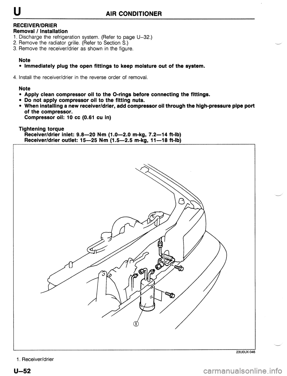
RECEIVER/DRIER
Removal / Installation
1. Discharge the refrigeration system. (Refer to page U-32.)
2. Remove the radiator grille. (Refer to Section S.)
3. Remove the receiver/drier as shown in the figure.
Note
l Immediately plug the open fittings to keep moisture out of the system.
4. Install the receiver/drier in the reverse order of removal.
Note
l Apply clean compressor oil to the O-rings before connecting the fittings.
l Do not apply compressor oil to the fitting nuts.
l When installing a new receiver/drier, add compressor oil through the high-pressure pipe port
of the compressor.
Compressor oil: 10 cc (0.61 cu in)
Tightening torque
Receiver/drier inlet: 9.8-20 N*m (1.0-2.0 m-kg, 7.2-14 ft-lb)
Receiver/drier outlet: 15-25 N-m (1.6-2.6 m-kg, 11-18 ft-lb)
1. Receiver/drier .-
u-52
Page 1009 of 1164
AIR CONDITIONER U
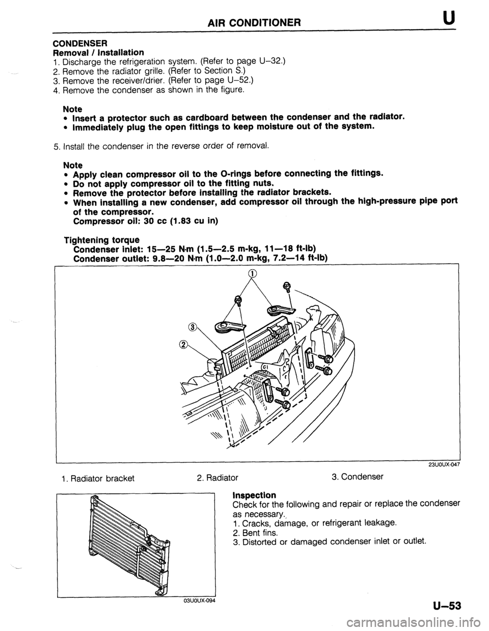
CONDENSER
Removal / Installation
1. Discharge the refrigeration system. (Refer to page U-32.)
2. Remove the radiator grille. (Refer to Section S.)
3. Remove the receiver/drier. (Refer to page U-52.)
4. Remove the condenser as shown in the figure.
Note
l Insert a protector such as cardboard between the condenser and the radiator.
l Immediately plug the open fittings to keep moisture out of the system.
5. install the condenser in the reverse order of removal.
Note
l Apply clean compressor oil to the O-rings before connecting the fittings.
l Do not apply compressor oil to the fitting nuts.
l Remove the protector before installing the radiator brackets.
l When installing a new condenser, add compressor oil through the high-pressure pipe port
of the compressor.
Compressor oil: 30 cc (1.83 cu in)
Tightening torque
Condenser inlet: 15-25 N*rn (1.5-2.5 m-kg, 11-18 ft-lb)
Condenser outlet: 9.8-20 N#m (1 .O-2.0 m-kg, 7.2-14 ft-lb)
1. Radiator bracket
2. Radiator 3. Condenser
23UOUX-01
Inspection
Check for the following and repair or replace the condenser
as necessary.;
1. Cracks, damage, or refrigerant leakage.
2. Bent fins.
3. Distorted or damaged condenser inlet or outlet.
u-53
Page 1010 of 1164
AIR CONDITIONER
REFRIGERANT LINES
On-vehicle Inspection
Check for leakage at connections. (Refer to page U-32.)
Repair or replace as necessary.
Replacement
1. Discharge the refrigeration system. (Refer to page U-32.)
2. Replace the faulty pipe or hose.
Note
l Immediately plug the open fittings to keep moisture out of the system.
l Apply clean compressor oil to the O-rings before connecting the fittings.
l Do not apply compressor oil to the fitting nuts.
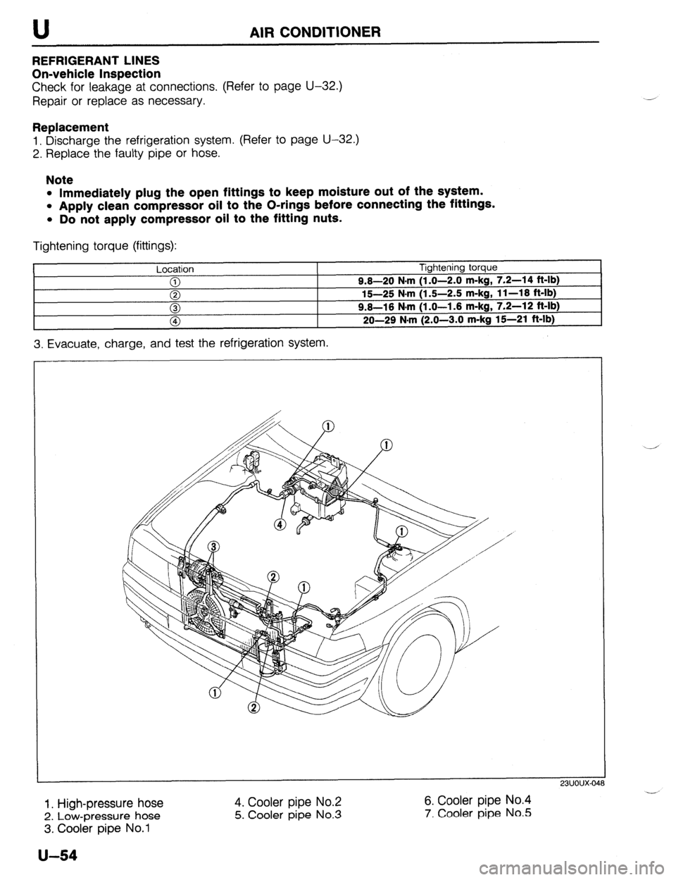
Tightening torque (fittings):
Location Tightening torque
0 9.8-20 N.m
(1.0-2.0 m-kg, 7.2-14 ft-lb)
0 15-25 N-m (1.5-2.5 m-kg, 11-18 ft-lb)
0 9.8-16 N.m (1.0-1.6 m-kg, 7.2-12 ft-lb)
fa 20-29 N.m
(2.0-3.0 m-ka 15-21 ft-lb)
3. Evacuate, charge, and test the refrigeration system.
1. High-pressure hose
2. Low-pressure hose
3. Cooler pipe No.1 4. Cooler pipe No.2 6. Cooler pipe No.4
5. Cooler
pipe No.3 7. Cooler pipe No.5
u-54
Page 1018 of 1164
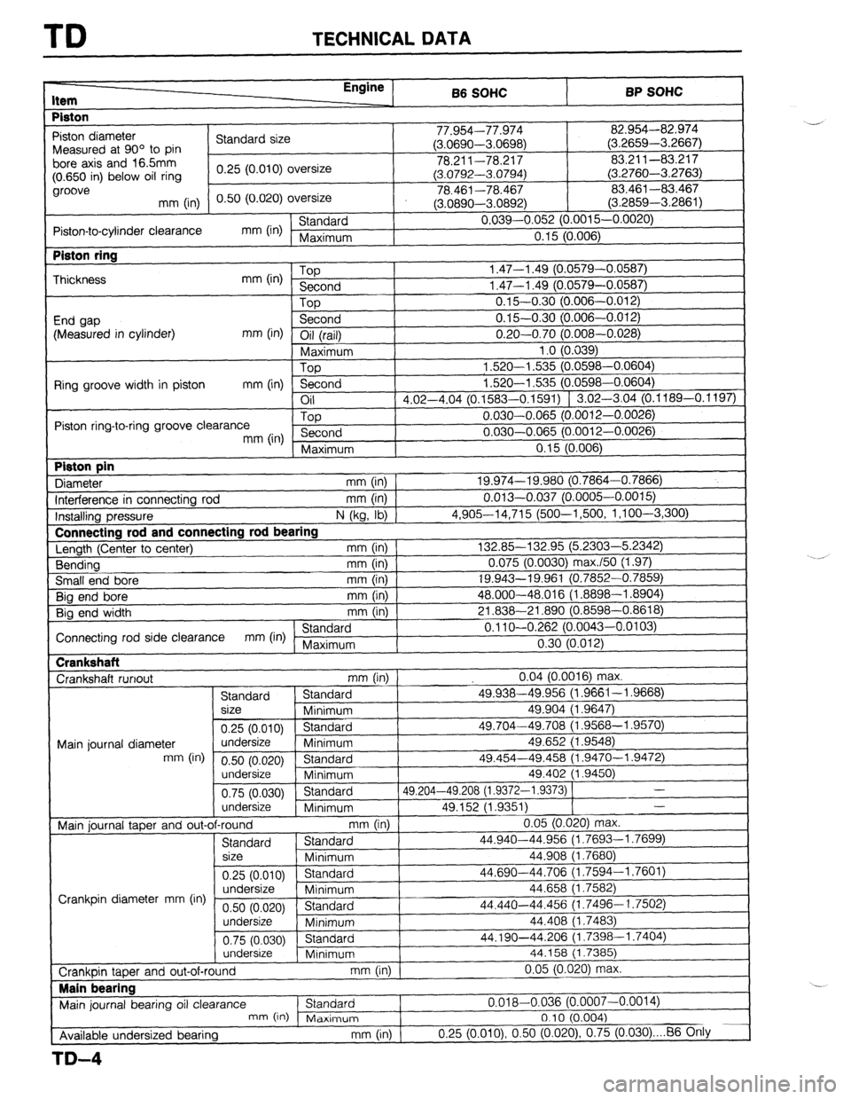
TD TECHNICAL DATA
I-
Item Enainc , 66 SOHC BP SOHC
Piston
, 1
-97 n-1 7-7 /t-r”
82.954-82.974
I -’
Piston diameter
Standard size I I I.Y34--1 l.YlG + I,-. nnnn
n r,Prx< > Measured at 90’ to pin (J.uoYY-mJoYo) (3.2659-3.2667)
bore axis and 165mm
I 78.211-78.217 83.211-83.217
(0.650 in) below oil ring 0.25 (0.010) oversize
(3.0792-3.0794) (3.2760-3.2763)
groove
0.50 (0.020) oversize 78.461-78.467 83.461-83.467
mm (in)
(3.0890-3.0892) (3.2859-3.2861)
Piston-to-cylinder clearance mm (in) Standard 0.039-0.052 (0.0015-0.0020)
Maximum 0.15 (0.006) Piston ring
Thickness
End gap
(Measured in cylinder) mm (in) Top
Second
Top
Second
mm (in) Oil (rail) I 1.47-l .49 (0.0579-0.05E
1.47-l .49 (0.0579-0.05E
0.15-0.30 (0.006-0.01~
0.15-0.30 (0.006-0.01; I Connectina rod and connectin
‘I ‘I 0.20-0.70 (0.008-0.028) 0.20-0.70 (0.008-0.028)
Maximum 1 .o (0.039) 1 .o (0.039)
Top 1,520-l ,535 (0.0598-0.0604) 1,520-l ,535 (0.0598-0.0604)
Ring groove width in piston
mm (in) Second 1.520-l ,535 (0.0598-0.0604) 1.520-l ,535 (0.0598-0.0604)
Oil
d d 117-4 04 (0 1583-O 1591) f ‘.02-3.04 (0.1189-0.1197) 117-4 04 ..“_ ..“. (0 1583-O 1591) f 1.02-3.04 (0.1189-0.1197)
\-“--- -’ - I
Piston ring-to-ring groove clearance Top 0.030-0.065 (O.O( 312-0.0026)
mm (in) Second 0.030-0.065 (O.O( 312-0.0026)
I
( Maximum
0 15 [email protected]) Piston pin
Diameter u,a, I KaEil mm (in) 1 111111 ,888, 19.974-19.980 (0.7864-0.7866) .“.“. _.__ J (0.7864-0.7866)
Interference in connecting rod ‘(0.0005-0.0015)
mm (In) 1 0.013-0.037 (0.0005-0.0015)
lnstallina pressure
N (kg, lb) 1 4,90614,715 (500-l ,500, 1 ,l oo-3,300) 4,90614,715 (500-l ,500, 1 ,l oo-3,300)
Length (Ceiter to center) Length (Ceiter to center) lg rod bearing lg rod bearing
mm (in) 1 mm (in) 1 132.85-132.95 (5.2303-5.2342) 132.85-132.95 (5.2303-5.2342)
Bending Bending mm (in) 1 mm (in) 1 0.075 (0.0030) max./50 (1.97) 0.075 (0.0030) max./50 (1.97)
Small end bore mm (in) 19.943-19.961 (0.; ‘852-0.7859) ‘852-0.7859)
Big end bore
mm (in) 48.000-48.016 (1 .f 3898-l .8904) 3898-l .8904)
Big end width mm (in) 21.838-21.890 f0.f 3598-0.8618)
I Connecting rod side clearance mm (in) Standard
! 0.11 O-O.262 (0.0043-0.0103)
Maximum 0.30 (0.012) Crankshaft
Crankshaft runout
mm (in) 0.04 (0.0016) max.
Standard Standard 49.938-49.956 (1.9661-I .9668)
size
Minimum 49.904 (1.9647)
0.25 (0.010) Standard 49.704-49.708 (1.9568-l .9570)
Main journal diameter undersize
Minimum 49.652 (1.9548)
mm (in)
0.50 (0.020) Standard 49.454-49.458 (1.9470-l .9472)
undersize
Minimum 49.402 (1.9450)
0.75 (0.030) Standard 49.204-49.208 (1.9372-I .9373) 1 -
undersize
Minimum 49.152 (1.9351) -
~.. Crankshaft
3598-0.8618j 1
I 0.11 O-O.262 (0.0043-0.0103)
0.30 (0.012)
1 Main iournal taoer and out-of-round
mm (in) I 0.05 (0.020) max.
Standard Standard 44.940-44.956 (i.7693-1.7699)
size
Minimum 44.908 (1.7680)
0.25 (0.010) Standard 44.690-44.706 (1.7594-l .7601)
undersize
Crankpin diameter mm (in) Minimum 44.658 (1.7582)
0.50 (0.020) Standard 44.440-44.456 (1.7496-I .7502)
undersize
Minimum 44.408 (1.7483)
0.75 (0.030) Standard 44.190-44.206 (1.7398-l .7404)
undersize
Minimum 44.158 (1.7385)
0.05 (0.020) max.
b
I I , I - \“‘---I 0.05 (0.020) max.
b
I I Crankuin taper and out-of-round
mm (In) I Main bearing
I
Main journal bearing oil clearance Standard
I 0.018-0.036 (0.0
mn-, ,i” .A- :-- -
c-l*,- ‘^’
Available undersized bearing
TD-4
007-0.0014)
I& II I I \” ‘,
, I”ld*llT,UIr1
I “. I J (U.004)
mm (in) 0.25 (O.OlO), 0.50 (0.020) 0.75 (0.030) . . . 86 Otily
Page 1019 of 1164
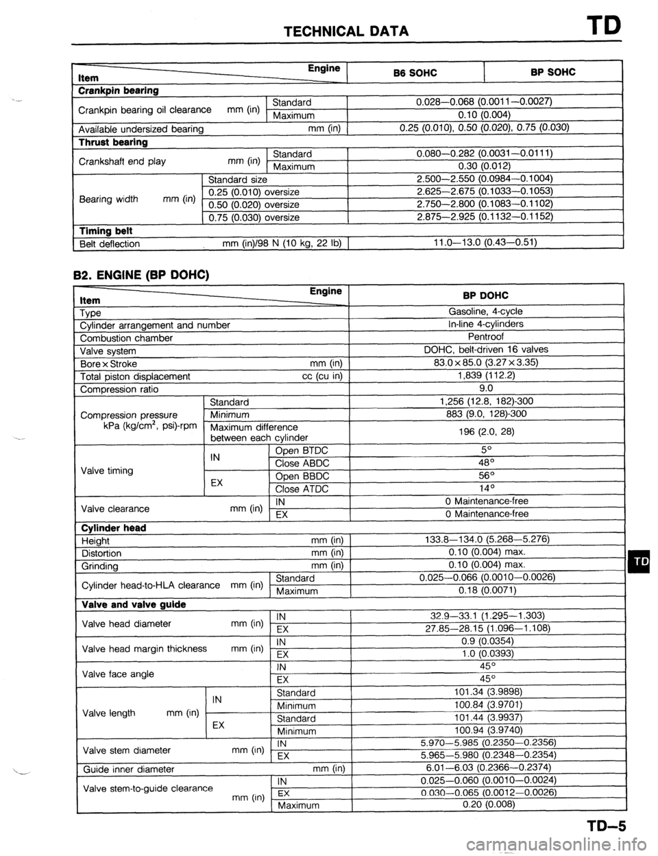
TECHNICAL DATA TD
r-
RP sm.lc: I Item
Crankpin bearing Engine
86 SOHC
I -. VW.._
Crankpin bearing oil clearance mm (in) Standard 0.028-0.068 (0.001 l-0.0027)
Maximum 0.10 (0.004)
Available undersized bearing mm (in)
0.25 (O.OlO), 0.50 (0.020) 0.75 (0.030) Thrust bearing
Crankshaft end play mm (in) Standard 0.080-0.282 (0.0031-0.0111)
Maximum 0.30 (0.012)
Standard size 2.500-2.550 (0.0984-0.1004)
Bearing width mm (in) 0.25 (0.010) oversize 2.625-2.675 (0.1033-0.1053)
0.50 (0.020) oversize 2.750-2.800 (0.1083-0.1102)
0.75 (0.030) oversize 2.875-2.925 (0.1132-0.1152)
1 Timing belt
Belt deflection mm (in)/98 N (10 kg, 22 lb) 1 11 .o-13.0 (0.43-0.51) 82.
ENGINE (BP DOHC) Item
Type
Cylinder arrangement and number BP DOHC
Gasoline, 4-cycle
In-line 4-cylinders
-. I
Combustion chamber
Valve svstem DOHC, belt-d
Bore x Stroke
Total piston displacement ventroot
riven
(3.2:
mm (in) 1 83.0 x 85.0
cc (cu in) ]
7x3.35)1 1,839 (112.2)
I 16 valves I 9.0
-300
mn Compression ratio
Standard 1,256 (12.8, 182)
Compression pressure Minimum 883 (9.0, 128)-Z kPa (kglcm2,
Psi)-rPm
Maximum dif
‘ference
between eat -, h cvlinder 196 (2.0, 28)
IN Open BTDC 5O
Valve timing Close ABDC 48’
EX Open BBDC 56O
Close ATDC .4 In
IY-
IN
mm (in) EX 0 Maintenance-l
Valve clearance
0 Maintenance-i ‘ree
‘me Cylinder head
Height mm (in)
Distortion mm (in)
Grinding mm (in)
Standard
Cylinder head-to-HLA clearance mm (in) Maximum Valve and valve guide 133.8-134.0 (5.268-5.276)
0.10 (0.004) max.
0.10 (0.004) max.
0.025-0.066 (0.0010-0.0026)
0.18 (0.0071)
Valve head diameter IN
mm (in) EX 32.9-33,l (1.295-l ,303)
27.85-28.15 (1.096-1.108)
Valve head margin thickness IN
mm On) Fx 0.9 (0.0354)
1 .o fO.0393)
1 Valve face angle . .
I
FX I I
Valve length IN
Standard 101.34 (3.9898)
mm (in) Minimum 100.84 (3.9701)
Standard 101.44 (3.9937) I -, .
I
Valve stem diameter EX
Minimum loo.94 i3.974oj
IN
mm (in) - EX 5.970-5.985 (0.2350-0.2356)
5.965-5.980 (0.2348-0.2354)
mm (in) I
. , , 6.01-6.03 (0.23 166-0.2374)
1 IN
I 0.025-0.060 (0.0010-0.0024)
3.0012-0.0026)
( Maximum 0.20 (0.008)
I
TD-5
Page 1022 of 1164
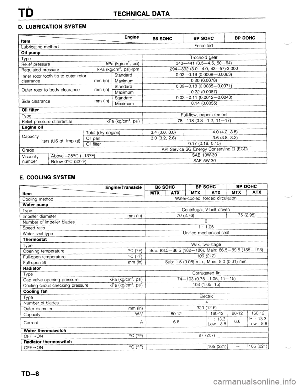
TECHNICAL DATA
D. LUBRICATION SYSTEM
Item I I bhricatinn mothnd
Engine
B6 SOHC BP SOHC
Force-fed BP DOHC 1
Requlated pressure kPa (kg/Cm”, p
Inner rotor tooth tip to outer rotor Standard
I-‘---- -.----,
clearance mm (in) Maximum 0.20 (0.0078)
Outer rotor to body clearance mm (in) Standard 0.09-0.18 (0.0035-0.0071)
Maximum 0.22 (0.0087)
Side clearance mm (in) Standard 0.03-0.11 (O.pniq n nnn=’
Maximum n4rl ‘-
“” I r-“.““+..I,
I “. I ‘t (U.0055)
I
1
Oil filter
_ Type
Relief pressure differential
Engine oil
I
Capacity
liters (US qt, Imp qt)
Grade
I Viscosity Full-flow, paper element
kPa (kg/cm’, psi) 1 78-l 18 (0.8-I .2, 1 l-l 7) Tntal /An, nnr*inol 3.4 (3.6, 3.0) 1 4.0 (4.2, 3.5)
3.0 (3.2, 2.6) 1 3.6 (3.8, 3.2)
VII 111Lb1 0.17 (0.18, 0.15)
API Service SG Energy Conserving II (ECQ
1
SA!f InW-Xl 1~ Above -25% (-13OF _ .-.. --
I
I
number
1 Below O’C (32OF) SAE 5W-30
1
E. COOLING SYSTEM
Cooling method EnginelTransaxle
MTX ] ATX 1 MTXl
Water-cooled, forced circulation
J B6 SOHC BP SOHC BP DOHC
, ATX 1 MTX ) ATX
LThermostat
Type Opening temperature
Full-open temperature
Full-open lift
Radiator
_ Type
Cap valve opening pressure
Cooling circuit checking pressure Wax, two-stage
“C (OF) Sub: 83.5-86.5 (182--188), Main: 86.5-89.5 (188-193)
OC (OF) 100 (212)
mm (in) Sub: 1.5 (0.06) min., Main: 8.0 (0.31) min.
Corrugated fin
kPa (kg/cm2, psi) 74-103 (0.75-1.05, 11-15)
kPa (kg/cm’, psi) 103 (1.05, 15)
~..
Cooling fan
Type Electric .-
Number of blades 4
_.---- _I___-
Outer diameter mm (in) 320 (12.6)
--_ ~~-
Capacity w-v 80-12 - 160-12 80-l 2 160-12
6.6 Hi : 13.3
6.6 Hi : 13.3
Current A
Low : 8.8 Low : 8.8
_------ ._____
Water thermoswitch
“c (OF) 1
OFF-ON 97 (207)
I--.
Radiator thermoswitch
__-I____-
OFF+ON “C (OF) 1 1105 (221)( - (105 (221)
TD-8