1992 MAZDA PROTEGE power steering
[x] Cancel search: power steeringPage 1006 of 1164
AIR CONDITIONER
Adjustment
Drive belt
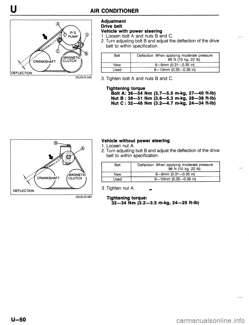
Vehicle with power steering
1. Loosen bolt A and nuts B and C.
2. Turn adjusting bolt B and adjust the deflection of the drive
belt to within specification.
23UOUX-045
Belt Deflection: When applying moderate pressure
98 N (IO kg, 22 lb)
New 8-9mm (0.31-0.35 in)
Used 9-l Omm (0.35-0.39 in)
3. Tighten bolt A and nuts B and C.
Tightening torque
Bolt A: 36-54 N-m (3.7-U m-kg, 27-40 ft-lb)
Nut B : 36-51 N-m (3.8-5.3 m-kg, 28-38 ft-lb)
Nut C : 32-46 N-m (3.2-4.7 m-kg, 24-34 ft-lb)
DEFLECTION
03uoux-087
Vehicle without power steering
1. Loosen nut A.
2. Turn adjusting bolt B and adjust the deflection of the drive
belt to within specification.
Belt
New
Used Deflection: When applying moderate pressure
98 N (10 kg, 22 lb)
8-9mm (0.31-0.35 in)
9-l Omm (0.35-0.39 in)
3 *Tighten nut A. .-,
Tightening torque:
32-34 N*m (3.2-3.5 m-kg, 24-25 Mb)
u-50
Page 1031 of 1164
TECHNICAL DATA TD
1 Throttle condition 1
nrllm pn-t
Mode Rr _ me/ flhrottle sensor 1 Shift 1 -.- -*r2d rpm
Vehicle speed I km/h (mohl , . ,
I
ioltage) 1 B6 sot
iC 1 BP SOHC 1 BP DOHC
66 SOHC 1 BP SOHC 1 BP
I I I
’ ni - n9 I’) 7nn-1 “50 2,500-3,05012,700-3.3001 I I DOHC
Fully opened 27-33 (17-201
3 D (4.0 volt) 50 2,050-2,55012,200-2,750]
40-50 i25-31 j
e I 300-500 1 450-650 / Q-15 16-9) 112-18 (7-111
00 3,250-3,45013,550-3.800~91-97 f56-60&G10’4 (61-64)hOO-106;62-&\I
s
i- f Fully closed
(0.5 volt)
YI -l&c
L, r vv-“,L
Dz + D3 2,150-2,7
D3 -+ DI 300--5O(
S3 -+ S2 3,200-3,4
’ L2 -+ LI 2,350-2,65012,200-2,50012,350-2.7001
43-49 ;27--3b1 ’ ‘I
M. FRONT AND REAR AXLES -
Item
Driveshaft Engine/Transaxle BP SOHC BP DOHC
Joint type
Length of shaft
Shaft diameter Front axle
Bearing play axial direction Rear axle
Bearing play axial direction Inside Tripod joint
Outside Ball joint
Right
919.3 (36.19) 918.7 (36.17) 630.7 (24.83)
mm (in) Left
637.8 (25.11) 640.2 (25.20) 621.2
637.1
(24.46) (25.08)
21.5 (0.85) 23.0 (0.91)
mm (in) 1 0.05 (0.002)
mm (in) I 0.05 (0.002)
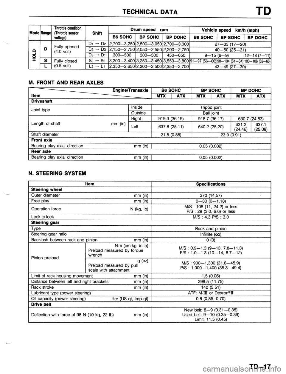
N. STEERING SYSTEM Steering wheel
Outer diameter Item Specifications 370 (14.57)
Lock-to-lock I Steering gear
--
Type
Steering gear ratio
Backlash between rack and pinion mm (in)
N.r ’ ’ ” ’ n (cm-Kg, in-01
Preload measured by torque
*rrv~rrdl Rack and pinion
Infinite (00)
0 (0)
M/S : 0.9-l .3 (Q-13, 7.8-l 1.3)
P/S : 1.0-1.3 (10-14, 8.7-12)
Pinion preload ““l~jll~,,
9 (0.4
Preload measured by pull
scale with attachment
Limit of rack housing movement mm (in)
Distance between left and right brackets mm (in)
Rack stroke mm (in M/S : 900-l ,300 (31.8-45.9)
P/S : l,OOO-1,400 (35.3-49.4)
1.5 (0.06)
298.5 (11.75)
140 (5.511
Lubricant type (power steering)
Oil capacity (power steering) Drive belt
liter (US qt, Imp qt) I ATF: M-III or DexronW
0.8 (0.85, 0.70)
I New belt: 8-Q (0.31-0.35)
Deflection with force of 98 N (10 kg, 22 lb) mm (in) Used belt: 9-10 (0.35-0.39)
I imit: 11.5 (0.461
TD-17
Page 1045 of 1164
SPECIAL TOOLS ST
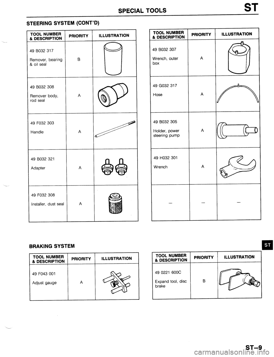
STEERING SYSTEM (CONT’D)
PRIORITY ILLUSTRATION I-OOL NUMBER
i DESCRIPTION PRIORITY ILLUSTRATION 1OOL NUMBER
h DESCRIPTION
-9 8032 307
19 8032 317
A
Yrench, outer
)0X ?emover, bearing
1 oil seal
19 GO32 317
-lose 19 B032 308
qemover body,
,od seal
49 F032 303 $9 8032 305
iolder, power
steering pump Handle A
A 49 HO32 301
Wrench A 49 B032 321
Adapter . .
49 F032 308
Installer. dust seal A - -
-
BRAKING SYSTEM
TOOL NUMBER
PRIORITY ILLUSTRATION TOOL NUMBER
& DESCRIPTION PRIORITY ILLUSTRATION
& DESCRIPTION
49 F043 001
Adjust gauge A 49 0221 600C
Expand tool, disc B
brake
ST-9
Page 1051 of 1164
PARTS
DIFFERENTIAL ..................................... Jl-52
SHIFT MECHANISM ............................. Jl-56
TRANSAXLE ............................................ Jl-8
TRANSAXLE OIL .................................... Jl-7
MANUAL TRANSAXLE (G5M-R) .................. J2-2
DIFFERENTIAL ..................................... J2-43
SHIFT MECHANISM ............................. J2-46
TRANSAXLE.. .......................................... J2-8
TRANSAXLE OIL .................................... J2-7
MOLDING, PROTECTOR, GARNISH ...........
S-42
BELTLINE MOLDING ............................. S-48
REAR WINDOW MOLDING.. ............. S-43,44
ROOF MOLDING.. .................................. S-46
SIDE PROTECTOR ................................. S-49
UPPER WINDSHIELD MOLDING,
A-PILLAR GARNISH ............................ S-42
NEUTRAL SWITCH (MTX) . . . . . . . . . . . . . . . . . . . . . . . . . . F-l 73
0
1
\_ OIL COOLER (ENGINE). ................................ D-8
OIL PAN (ENGINE) ........................................ D-9
OIL PUMP (ENGINE) ................................... D-l 3
..................................... F-l 71
OXYGEN SENSOR
P
PARKING BRAKE ......................................... P-31
PARKING BRAKE CABLE ............................ P-32
PARKING BRAKE LEVER ............................ P-33
PARKING BRAKE SHOE ............................. P-31
PASSIVE SHOULDER BELT SYSTEM.. ..... S-103
DOOR CATCH SWITCH ....................... S-l 07
LIMIT SWITCH ...................................... S-l 07
PASSIVE SHOULDER BELT MOTOR.. S-106
SPEED SENSOR ................................... S-l 07
WARNING SWITCH .............................. S-l 07
PCV VALVE ................................................
POWER BRAKE UNIT ‘;--=I;;
..................................
POWER DOOR LOCK SYSTEM ................... S-23
DOOR LOCK CONTROL.. ...................... S-26
DOOR LOCK SWITCH.. .......................... S-26
DOOR LOCK TIMER AND RELAY.. ....... S-26
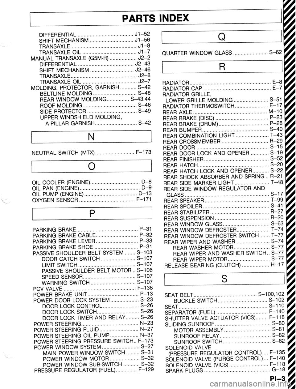
POWER STEERING.. .................................... N-23
POWER STEERING FLUID .......................... N-27
POWER STEERING OIL PUMP.. ................. N-37
POWER STEERING PRESSURE SWITCH . . F-l 73
POWER WINDOW SYSTEM.. .......................
S-27
MAIN POWER WINDOW SWITCH.. .......
S-31
POWER WINDOW MOTOR.. ..................
S-32
POWER WINDOW SUB-SWITCH ........... S-32
PRESSURE REGULATOR (FUEL). ............. F-l 29 . . . . . . . . , . . . . . , . RADIATOR CAP .............................................
E-7
RADIATOR GRILLE,
I
LOWER GRILLE MOLDING ....................... S-51 fl
RADIATOR THERMOSWITCH ...................... E-17 t
REAR AXLE ................................................. M-10
REAR BRAKE (DISC) ................................... P-23
REAR BRAKE (DRUM) ................................. P-28
REAR BUMPER ............................................ s-40
REAR COMBINATION LIGHT.. ....
REAR CROSSMEMBER ............................... R-29
REAR DOOR ................................................ S-l 5
REAR DOOR LOCK AND OPENER.. .
REAR FINISHER ........................................... s-52
REAR HATCH ............................................... s-20
REAR HATCH LOCK AND OPENER.. ......... S-22
REAR SHOCK ABSORBER AND SPRING.. R-21
REAR SIDE MARKER LIGHT ....................... T-48
REAR SIDE WINDOW REGULATOR AND . . . . . . . . .
AI .,.n
INDEX
Q
QUARTER WINDOW GLASS . . . . . . . . . . . . ..a........ S-62
R
RADIATOR . . . . . . . . . . . . . . . . . . . . . . . . . . . . . . . . . . . . . . . . . . . . . . . . . . . . . .
kiLA33 ........................................................ a-- I I
REAR SPEAKER ........................................... T-99
REAR SPOILER ............................................ s-41
REAR STABILIZER.. ..................................... R-27
REAR SUSPENSION .................................... R-20
REAR WINDOW GLASS ............................... S-63
REAR WINDOW DEFROSTER.. .................... T-74
REAR WINDOW DEFROSTER SWITCH ....... T-77
REAR WIPER AND WASHER ...................... S-74
REAR WASHER MOTOF
REAR WIPER AND WASHER SWITCH . . S-77
REAR WIPER MOTOR ............................ s-77
RELEASE BEARING (CLUTCH). . . . . . . . . . ..s..... H-17 I . . . . . . . . ...*. .*......*..
SEAT BELT.. ........................................ S-100,102
BUCKLE SWITCH.. ............................... S-l 02
SEAT ........................................................... s-110
SEPARATOR (FUEL) .................................. F-l 40
SHUTTER VALVE ACTUATOR (VICS) ........ F-l 18
SLIDING SUNROOF ..................................... S-80
MOTOR ASSEMBLY ............................... S-81
SUNROOF RELAY.. ................................ S-82
SUNROOF SWITCH.. .............................. S-82
SOLENOID VALVE
(PRESSURE REGULATOR CONTROL) .... F-135
SOLENOID VALVE (PURGE CONTROL). .. F-140
SOLENOID VALVE (VICS) .......................... F-l 18
SPARK PLUGS ............................................ G-18
-II__
Page 1060 of 1164
Z-Gl-4 Reading Wiring Diagrams
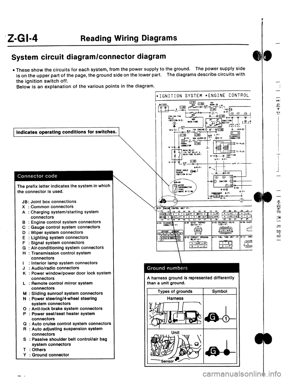
System circuit diagram/connector diagram
l These show the circuits for each system, from the power supply to the ground. The power supply side
is on the upper part of the page, the ground side on the lower part. The diagrams describe circuits with
the ignition switch off.
Below is an explanation of the various points in the diagram.
) Indicates operating conditions for switches.
The prefix letter indicates the system in which
:he connector is used.
JB: Joint box connections
X : Common connectors
A : Charging system/starting system
connectors
B : Engine control system connectors
C : Gauge control system connectors
D : Wiper system connectors
E : Lighting system connectors
F : Signal system connectors
G : Air-conditioning system connectors
H : Transmission control system
connectors
I : Interior lamp system connectors
J : Audio/radio connectors
K : Power window/power door lock system
connectors
L : Remote control mirror system
connectors
M : Sliding sunroof system connectors
N : Power steering/4-wheel steering
system connectors
0 : Anti-lock brake system connectors
P : Power seat/seat heater system
connectors
Cl : Auto cruise control system connectors
R : Auto adjusting suspension system
connectors
S : Passive shoulder belt control/air bag
system connectors
T : Others
Y : Ground connector
- .
1
\\‘
IGNITION SYSTEM l ENGINE CONTROL 9 harness ground is represented differently
:han a unit ground.
Types of grounds Symbol
Harness
I
-
-
-
-
‘“G:
si-
P
7:’
.I
I
I
.i
-
-
-
f
9
Tiii
zs
LL
a
EE
-
Page 1066 of 1164
Z-GI-10 Reading Wiring Diagrams
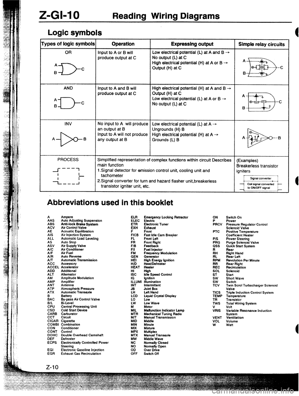
Logic symbols
‘ypes of logic symbols Operation Expressing output Simple relay circuits
OR Input to A or 6 will Low electrical potential (L) at A and B --,
produce output at C No output (L) at C
High electrical potential (H) at A or B -+ A
A
ID- C Output (H) at C
EB Q-f2 c
B B
AND Input to A and B will High electrical potential (H) at A and B -+
produce output at C Output (H) at C
A _
A
El-- Low electrical potential (L) at A or B -+
B C
No output (L) at C
B
II!I3 Q-00-Q
C
INV No input to A will produce Low electrical potential (L) at A +
an output at B
Ungrounds (H) B
-b- Input to A will not produce High electrical potential (H) at A +
A B
any output at B Grounds (L) B A-
El
PROCESS Simplified representation of complex functions within circuit Describes (Examples)
main function
Breakerless transistor
---
-I- 1 1 Signal detector for emission control unit, cooling unit and
I igniters
- ~._..._...._._..._._..__,
--L--A tachometer
P.Signal converter for turn and hazard flasher unit,breakerless : siinalcon”elter :
i..-.--...-.........---i
transistor igniter unit, etc. --j CoIlsignal ConVerted e
--I. .‘p. Y?YT?!!9’. . _ i
Abbreviations used in this booklet
A
%J Ampere
Auto Stop
Air Supply Valve
A/C AAS
Air Conditioner Auto Adjusting Suspension
A/F Air Fuel ABS
AIR Anti-lock Brake System
Auto Reverse
A/T ACV
Automatic Transmission
ACC Air Control Vafve
Acc%K4tIory
ACCEL Accelerator
ADD AE
Additional Acoustic Equilibration
ALT Alternator
EP AIS
Amplitude Modulation Air Injection System
Amplifier ALL
ANT Antenna Automatic Load Levelino
ATP Atmospheric Pressure
ATX Automatic Tmnsaxle FR Fmnt Right ELI?
FIB Feedback
F/I Fuel Injector Emergency Locking Retractor
EN ELEC Electric
Frequency Modulation
Generator
HEI Electronic Tuner
Hiih Energy lgnitiin
HID K!
Heat/Defmster
HEAT Heater Exhaust
HI Hiih F
ISC Front
Idk Speed Contml
IG Ignition
ILLUMI Illumination FICB
INT Intermittent FL Fast Idle Cam Breaker
Fmnt Left
JB
LH Joint Box
Left Hand
:AC Battery
Bypass Air Control Valve
B/L Ei-Level
CPU Central Pmcessing Unit
CSD COM start Device
CARB Carburator
CCT Circuit
CIGAR Cigarette
COMBI Combination
CON Conditioner
CONT Control
DOHC Double Overhead Camshaft
DEF Defroster
ECPS Electronicalfy Controlfed Power
Steering
EGI Electronic Gasoline Injection
EGR Exhaust Gas Recirculation LCD Liquid Crystal Display
:i Low
Low Wave
/IL Motor
MaWunction Indicator Lamp
MTR Mechanical Tuning Radio
Mrr Manual Transmission
MID Mkfdk,
MIN Minute
MIX
MiXtUt MPX Mukiplex
MTX Manual Transaxte
K Middle Wave
Normalty Closed
too Normally Open
Over Drive
OFF Switch Off ON
FRCV
PTC
P/S
PRG
ass
ii:
RPM
EC
SOL
ST
Et TCV
TICS
TEMP
ES
V
VRIS
VENT
VOL
W Switch On
Power
Pressure Regulator Control
Solenoid Valve
Positiie Temperature
Coefficiint Heater
Power Steering
Purge Solenoid Vahe
Quick Start System
Rear
Riiht Hand
Rear Left
Revolution Per Minute
Rear Right
Recirculation
Solenoid
Start
Short Wave
Switch
~;eScml Turbocharger Solenoid
Triple Induction Control System
Temperature
Transistor
Total Wiring System
volt
Variable Resonance Induction
System
Ventilation
Volume
Wan
Page 1084 of 1164
. ” . ..S1.” Yrne-aU. .-m
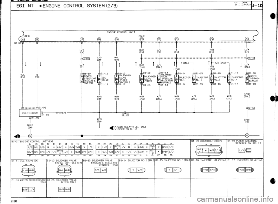
EGI MT = ENGINE CONTROL SYSTEM (2/3)
1 1
OISTRIBUTOR W/R (EM)
Ez
%P
MAIN RELAY (FUEL INJ)
(SECTION B-la)
*
w
11-O: ENGINE CONTROL UNIT (EM) Bi-09 DISTRIBUTOR (EM) Bl-10 POWER STEERING
2" IS 1Q 10 1M IK 11 1G IE 1C IA 2Y 2W 2U 25 20 20 3-l 2K 21 26 2E 2C 2A PRESSURE SW ITCH (F)
* L/O Y yy L/W R
ll-11 ISC VALVE(EM)
31-18 WATER THERMOS:~;;j;Bl-25 SOLENOID VALVE
(~1123 (INJ)
2-28 .
Page 1092 of 1164
WIRINQ MAQRAM
o...DoHc
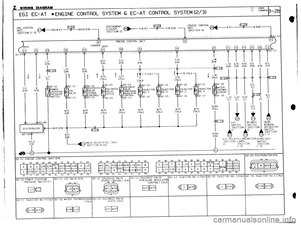
EGI EC-AT mENGINE CONTROL SYSTEM &i EC-AT CONTROL SYSTEM(2/3)
~II;~CONTROL
(SECTION E-3) @+...-BR/w IF) ~BR/W (EM) 1
~~~~j @--- Y/B (F) s Y/B (EM) 1
3F ENGINE CONTROL UNIT
1E
CANADA DOHC
31 3M 3u 3V 2E IL 10 IH 1P 1Q
2A IN 3Q 20
2-01y==---- --~-- _._----.-. ------~---
I I
I I
x? G/O
GM, Y/B
(EM) (EM) I I I
L/Y [FM
MAIN RELAY (FUEL INJ)
(SECTION B-2a) A/C RELAY ILL~l
(SECTION LA&
G)
I-4) Gl
i 1
b 26
REAR
WINDOW
(SECTION DEFROSTER
SWITCH
(SECTION
25 I-l)
\IATIONSTOPLIGHT
SWITCH
3N
(SECTION
F-2) lMIl
‘S
:TII
82-09 DISTRIBUTOR (EM)
2-01 ENGINE CONTROL UNITCEM)
20 2M 2K 21 2G 2E 2C 2A 3~ 3w 3” 3s 3~ 30 3M 3K 31 36 3~ 3C 7A
-I 1
I I I , __ , ,, .,- ,, f 1 I I,
,“I 11 1 ,^ 1 1 I ,” I ., I: B/R 1 v I,.,
I v lb ,I c _ 11: ,S 113 10
IM IK 11 1G 1E
1~ 1A
* W
* R/W B/L O/L~L/Y[L/BIB/LIR/BIW/B(IYY/YIU(/R
3” IT IR IP ,N IL IJ 1H IF 3D lF?
z-10 POWER STEERING
PRESSURE SWITCH (Fl W/L W/L R/BFG/qW/UIL/WIH/Li W
k”,, -L_ .A _ ,, I_ ,^ , _
R/YY/LI * (-‘;--pH/kpqwb( H 1 L L/1 ‘,tl,, * , * , x , * , * , m ,‘,“, * IF’“” ‘,“‘V
2P 2N 2L 2J 2H 2F 20 28 32 3x 3V 37 ~~ ~- --’ -’ -‘ -” 7r =” =(1 3R 3P 39 3L zw 311 Jr JY _I”
I 62-13 SOLENOID VALVE ~2-14
INJECTOR No.t(INJ) 82-15 INJECTOR N0.3(INJ) 82-16 INJECTOR N0.2(INJ)
(PRESSURE REGULATO 82-11
I
EC
VALVE
82-11
12-25 SOLENOID VALVE
wrcs) (INJ)