1992 MAZDA PROTEGE oil level
[x] Cancel search: oil levelPage 917 of 1164

WARNING SYSTEM T
13UOTX-07
63U15X-05
, I//
‘nF -
-
-
FUEL
13UOTX.08C
- CHARGE
13UOTX-08
13UOTX-08
Inspection
Brake system warning lamp
1. Disconnect the connector from the brake fluid level sensor.
2. Connect a jumper wire between “G/Y” and “6” terminal
(body ground).
3. Start the engine and check that the BRAKE warning lamp
illuminates.
Caution
l Be sure that the parking brake is fully released be-
fore checking.
4. If there is no illumination, check the fuse, bulb, and wiring
harness.
Brake fluid level sensor
Connect an ohmmeter to each terminal of the brake fluid lev-
el sensor connector.
Check for continuity when the float is moved up and down.
The sensor is good if there is continuity when the float is be-
low the “MIN” mark, and if there is no continuity when the
float is above the “MAX” mark. If the sensor does not pass
this test, replace it.
Fuel-level warning lamp
1. Disconnect the connector from the fuel tank unit.
2. Connect the connector terminal “W/R” to the body ground.
3. Start the engine and check that the FUEL warning lamp il-
luminates.
4. If there is no illumination, check the fuse, warning lamp, and
wiring harness.
Alternator warning lamp
1. Start the engine, connect the connector terminal “W/B” to
a body ground.
2. Check that the alternator warning lamp illuminates.
3. If there is no illumination, check the warning lamps, wiring
harness and alternator. Replace or repair as necessary.
Engine oil pressure warning lamp
1. Disconnect the connector from the oil pressure switch.
2. Start the engine and connect the connector terminal “Y/R”
to a body ground.
3. Check that the “OIL” warning lamp illuminates. If it does
not, replace the sender switch or repair the wiring harness
if bulb is not burnt out.
T-61
Page 1033 of 1164

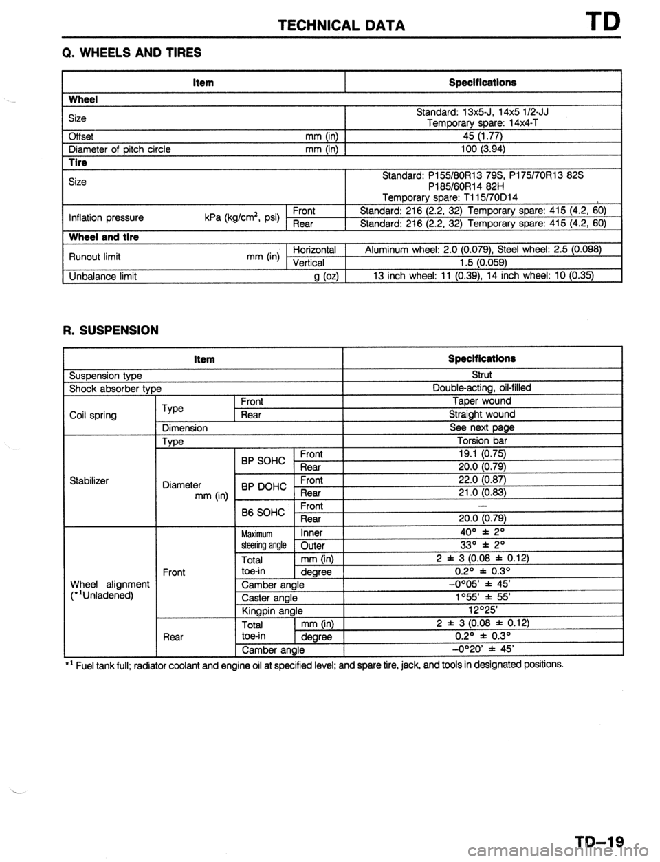
TECHNICAL DATA
Q. WHEELS AND TIRES
Item Specifications
Wheel
Size
Off set Standard: 13x5-J, 14x5 l/2-JJ
Temporary
mm (in) 1 _ spare: 14x4-T
45 (1.77)
I Diameter of oitch circle
mm (in) I 100 (3.94)
r I Pl
-
Inflation pressure kPa (kg/cm*, psi) Front 1 8
I 9
Runout limit
Unbalance limit mm (in) ;lii.raltLa’
a (02) ’
13 inch wheel: 11 (0.
R. SUSPENSION Item Specifications
Suspension type Strut
)e Double-acting, oil-filled
I Shock absorber tyf
Coil spring
Type
Dimension
Type Front Taper wound
Rear Straight wound
See next page
Torsion bar
I
I C.rrn,
19.1 (0.75)
20.0 (0.79)
22.0 (0.87)
21 .O f0.83)
Wheel alignment
(“‘Unladened) BP SOHC ;;a;
Diameter
mm (in) BP DOHC - ;la;t
Front -
B6 SOHC
Rear 20.0 (0.79)
Maximum Inner 4o” f 2O
steering angle Outer
Total mm (in) 2 f 3 (0.08 j
Front toe-in
dearee
.-.._
Rear
.--. I --- ~~
Camber angle
Caster angle
Kingpin angle
I Total
I mm OnI I I toe-in
1 dearee I , --U’-- 1
Camber angle
I 33O * 2O
: 0.12)
0.2O f 0.3O
-0OO5’ * 45’
1055’ * 55’
12O25’
2 f 3 (0.08 f 0.12)
0.2O f 0.3O
-0°20’ f 45’
l ’ Fuel tank full; radiator coolant and engine ail at specified level; and spare tire, jack, and tools in designated posmons.
TD-19
Page 1066 of 1164

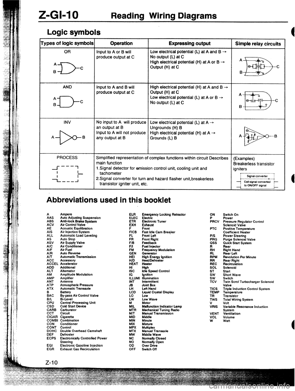
Z-GI-10 Reading Wiring Diagrams
Logic symbols
‘ypes of logic symbols Operation Expressing output Simple relay circuits
OR Input to A or 6 will Low electrical potential (L) at A and B --,
produce output at C No output (L) at C
High electrical potential (H) at A or B -+ A
A
ID- C Output (H) at C
EB Q-f2 c
B B
AND Input to A and B will High electrical potential (H) at A and B -+
produce output at C Output (H) at C
A _
A
El-- Low electrical potential (L) at A or B -+
B C
No output (L) at C
B
II!I3 Q-00-Q
C
INV No input to A will produce Low electrical potential (L) at A +
an output at B
Ungrounds (H) B
-b- Input to A will not produce High electrical potential (H) at A +
A B
any output at B Grounds (L) B A-
El
PROCESS Simplified representation of complex functions within circuit Describes (Examples)
main function
Breakerless transistor
---
-I- 1 1 Signal detector for emission control unit, cooling unit and
I igniters
- ~._..._...._._..._._..__,
--L--A tachometer
P.Signal converter for turn and hazard flasher unit,breakerless : siinalcon”elter :
i..-.--...-.........---i
transistor igniter unit, etc. --j CoIlsignal ConVerted e
--I. .‘p. Y?YT?!!9’. . _ i
Abbreviations used in this booklet
A
%J Ampere
Auto Stop
Air Supply Valve
A/C AAS
Air Conditioner Auto Adjusting Suspension
A/F Air Fuel ABS
AIR Anti-lock Brake System
Auto Reverse
A/T ACV
Automatic Transmission
ACC Air Control Vafve
Acc%K4tIory
ACCEL Accelerator
ADD AE
Additional Acoustic Equilibration
ALT Alternator
EP AIS
Amplitude Modulation Air Injection System
Amplifier ALL
ANT Antenna Automatic Load Levelino
ATP Atmospheric Pressure
ATX Automatic Tmnsaxle FR Fmnt Right ELI?
FIB Feedback
F/I Fuel Injector Emergency Locking Retractor
EN ELEC Electric
Frequency Modulation
Generator
HEI Electronic Tuner
Hiih Energy lgnitiin
HID K!
Heat/Defmster
HEAT Heater Exhaust
HI Hiih F
ISC Front
Idk Speed Contml
IG Ignition
ILLUMI Illumination FICB
INT Intermittent FL Fast Idle Cam Breaker
Fmnt Left
JB
LH Joint Box
Left Hand
:AC Battery
Bypass Air Control Valve
B/L Ei-Level
CPU Central Pmcessing Unit
CSD COM start Device
CARB Carburator
CCT Circuit
CIGAR Cigarette
COMBI Combination
CON Conditioner
CONT Control
DOHC Double Overhead Camshaft
DEF Defroster
ECPS Electronicalfy Controlfed Power
Steering
EGI Electronic Gasoline Injection
EGR Exhaust Gas Recirculation LCD Liquid Crystal Display
:i Low
Low Wave
/IL Motor
MaWunction Indicator Lamp
MTR Mechanical Tuning Radio
Mrr Manual Transmission
MID Mkfdk,
MIN Minute
MIX
MiXtUt MPX Mukiplex
MTX Manual Transaxte
K Middle Wave
Normalty Closed
too Normally Open
Over Drive
OFF Switch Off ON
FRCV
PTC
P/S
PRG
ass
ii:
RPM
EC
SOL
ST
Et TCV
TICS
TEMP
ES
V
VRIS
VENT
VOL
W Switch On
Power
Pressure Regulator Control
Solenoid Valve
Positiie Temperature
Coefficiint Heater
Power Steering
Purge Solenoid Vahe
Quick Start System
Rear
Riiht Hand
Rear Left
Revolution Per Minute
Rear Right
Recirculation
Solenoid
Start
Short Wave
Switch
~;eScml Turbocharger Solenoid
Triple Induction Control System
Temperature
Transistor
Total Wiring System
volt
Variable Resonance Induction
System
Ventilation
Volume
Wan
Page 1163 of 1164

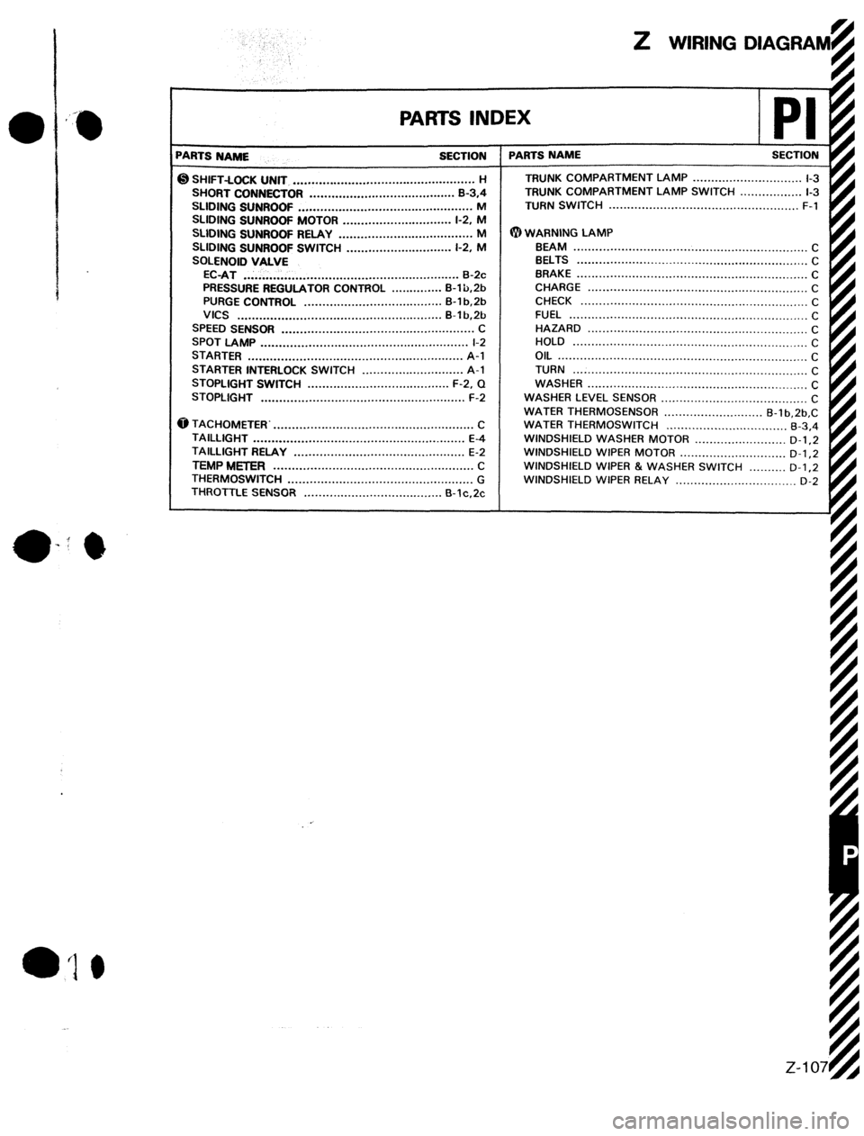
PAWS INDEX
‘ARTS NAME SECTION
@ SHIFT-LOCK UNfT .................................................. H
SHORT CONNECTOR ........................................ B-3,4
SLIDING SUNROOF ................................................ M
SLIDING SUNROOf MOTOR .............................. l-2. M
SLlDlNG SUNROOF RELAY ..................................... M
SLIDING SUNROOF SWITCH ............................. l-2, M
SOLENOID VALVE
EC-AT ........................................................... 8-2~
PRESSURE REGULATOR CONTROL .............. B-l b,2b
PURGE CONTROL ...................................... B-l b.2b
VICS ........................................................ B-lb,Sb
SPEED SENSOR ..................................................... C
SPOT LAMP ......................................................... l-2
STARTER ........................................................... A-l
STARTER INTERLOCK SWITCH ............................ A-l
STOPLIGHT SWITCH ....................................... F-2, Q
STOPLIGHT ........................................................ F-2
@ TACHOMETER.. ...................................................... C
TAILLIGHT .......................................................... E-4
TAILLIGHT RELAY ............................................... E-2
TEMP METER ....................................................... c
THERMOSWITCH ................................................... G
THROTTLE SENSOR ...................................... B-lc.2~ 1 PARTS NAME SECTION
TRUNK COMPARTMENT LAMP
r ~~~~~~
.............................. l-3
TRUNK COMPARTMENT LAMP SWITCH ................. l-3
TURN SWITCH ....................................................
F-l
@WARNING LAMP
BEAM ................................................................ C
BELTS ...............................................................
C
BRAKE
............................................................... C
CHARGE ............................................................
C
CHECK .............................................................. C
FUEL ................................................................. C
HAZARD ............................................................
C
HOLD ................................................................ C
OIL ....................................................................
C
TURN ................................................................
C
WASHER
............................................................
C
WASHER LEVEL SENSOR
........................................ C
WATER THERMOSENSOR ........................... B-l b,2b,C
WATER THERMOSWITCH ................................. B-3.4
WINDSHIELD WASHER
MOTOR .........................
D-l .2
WINDSHIELD WIPER
MOTOR ............................. D-l,2
WINDSHIELD WIPER & WASHER SWITCH .......... D-1.2
WINDSHIELD WIPER RELAY ................................. D-2