Page 715 of 1164
WHEEL ALIGNMENT
REAR WHEEL ALIGNMENT
Specifications
kern Specifications
Total mm (in) 2 f 3 (0.08 f 0.12)
Wheel alignment
(*‘Unladen) Rear toe-in
degree 0.2O f 0.3O
Camber angle -0020’ f 45’
*I Fuel tank full; radiator coolant and engine oil at specified level; and spare tire, jack, and tools in designated positions.
13UORX-012
Adjustment
Total toe-in
1. Loosen the lateral link locknuts.
2. Turn the lateral link adjustment link to adjust.
Note
l One turn of the link changes 11.3mm (0.44 in).
3. Tighten the lateral link locknuts to the specified torque.
Tightening torque:
55-64 N,m (5.6-6.5 m-kg, 41-47 ft-lb)
R-9
Page 718 of 1164
FRONT SUSPENSION (STRUT)
Installation note
Shock absorber and spring
1. Face the direction indicator of the mounting block inboard,
and install the shock absorber and spring.
Note
l When facing the indicator to other position, the cam-
ber and caster are changed as shown in the page
R-8. -’
23UORX-017
Disassembly / Inspection
1. Disassemble in the order shown in the figure, referring to Disassembly Note.
2. Visuallv inspect each part and replace as necessary.
1. Cap
2. Piston rod nut
Disassembly Note ,..........,.....,.... page R-13
3. Mounting block
4. Thrust bearing 5. Upper spring seat
6. Rubber spring seat
7. Bound stopper
8. Coil spring
9. Shock absorber
Inspection . . . . . . . . . , . . . . , . . . . . . . . . . . . . . . . . . . . page R-l 3
R-l 2
Page 719 of 1164
FRONT SUSPENSION (STRUT)
R
03UORX-022
.
.
H 03UOAX-02:
03UORX-02r
Disassembly note
Piston rod nut
1. Secure the mounting block in a vise.
Caution
l Use protective plates in the jaws of the vise.
2. Loosen the piston rod nut a few turns. Do not remove it.
Caution
l Do not remove the nut.
3. Compress the coil spring with the SST.
4. Remove the piston rod nut.
5. Remove the coil spring.
Inspection
Check for the following and replace the shock absorber if
necessary.
Secure a handle to the piston rod, and compress and expand
the shock piston at least three times. Verify that the operation-
al force does not change and that there is no unusual noise.
R-13
Page 729 of 1164
REAR SUSPENSION (STRUT)
03UORX-04
3. Compress the coil spring with the SST.
4. Remove the piston rod nut.
5. Remove the coil spring.
Inspection
Check for the following and replace the shock absorber, if
necessary.
Rear shock absorber function inspection
Secure a handle to the piston rod, and compress and expand
the shock piston at least three times, Verify that the operation-
al force does not change and that there is no unusual noise.
R-23
Page 866 of 1164
T
ELECTRICAL SYMBOLS
Switches and Relays OUTLINE
There is an NC (normally closed) and NO (normally open) indication for switches and relays which shows
when no change of operation conditions has occurred.
Relay Switch
NO type relay NC type relay NO switch NC switch
Not in operation
(No power supply) +E+ #Fig -o-- -da--
ax ax
STOP
FLOW STOP FLOW
In operation
(Power supply) * !jiij! kiig 6 dLe
cw r”X
FLOW STOP FLOW STOP
Other Electrical Symbols
BATTERY
THERMISTER DIODE CONDENSER
Q
M
MOTOR I
T-10
l-
BODY GROUND
COIL, SOLENOID i
0 8 HOLDER BOX
FUSE
RESISTOR
1
T
FUSIBLE LINK
1 i 1
VARIABLE RESISTOR
LIGHT
HEATER
69G15X-O(
Page 1065 of 1164

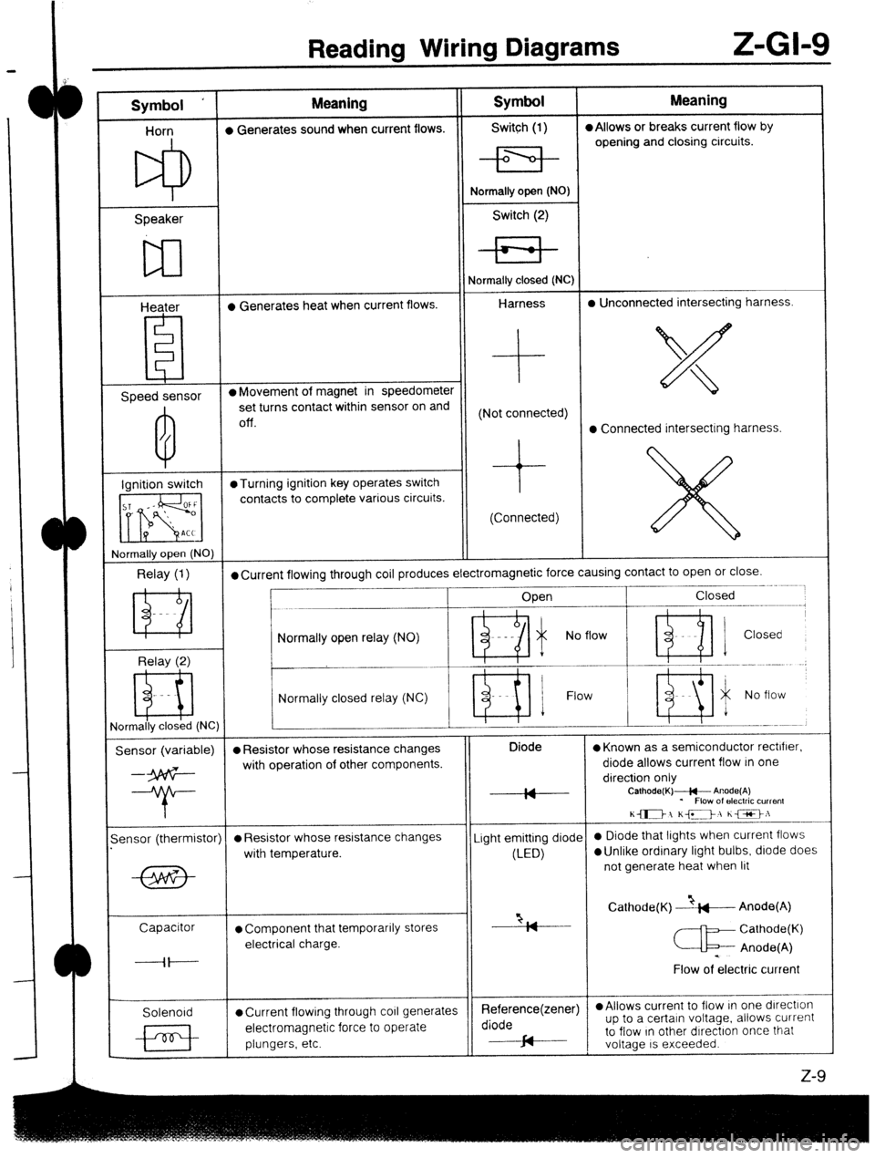
Reading Wiring Diagrams Z-GI-9
Symbol ‘ Meaning Symbol Meaning
Horn l Generates sound when current flows. Switch (1) l Allows or breaks current flow by
opening and closing circuits.
Speaker
w
Heater l Generates heat when current flows. Normally open (NO)
Switch (2)
Normally closed (NC)
Harness l Unconnected intersecting harness.
Speed sensor l Movement of magnet in speedometer
set turns contact within sensor on and
Off. (Not connected)
l Connected intersecting harness.
Ignition switch @Turning ignition key operates switch
contacts to complete various circuits.
(Connected)
rlormally open (NO)
Relay (1) l Current flowing through coil produces electromagnetic force causing contact to open or close.
____- .~.~~
Open Closed
--.--.-m.---------,
Relay (2) Normally open relay (NO)
- Ri i No flow ’ ni 1 Closed
Normally closed relay (NC) Flow
ormally closed (NC)
Sensor (variable) l Resistor whose resistance changes Diode
l Known as a semiconductor rectifier.
--3p6G- with operation of other components. diode allows current flow in one
direction only
--T- IA
IY Calhode(K)+- Anode(A)
* Flow of electric current
K-1 KD, he>:
-
ensor (thermistor)
l Resistor whose resistance changes Light emitting diode 0 Diode that lights when current flows
with temperature.
(LED)
l Unlike ordinary light bulbs, diode does
not generate heat when lit
Capacitor
l Component that temporarily stores “2, Cathode(K) --&---Anode(A)
I7
Cathode(K)
electrical charge.
c Anode(A)
----il---- .
Flow of electric current
Solenoid
l Current flowing through co11 generates Reference(zener) l Allows current to flow In one dlrectlon
electromagnetic force to operate diode up to a certain voltage. allows current
plungers, etc. cd to flow In other dIrectron once that
J-
voltage IS exceeded.
z-9
Page:
< prev 1-8 9-16 17-24