1992 MAZDA PROTEGE length
[x] Cancel search: lengthPage 800 of 1164

S REAR WINDOW GLASS
HATCHBACK
1
J
03UOSX-106
1. Rear wiper arm and blade
Removal / Installation . . . . . . . . . . . . . . . . . . page S-78
2. Rear window molding
Removal. . . . . . . . . . . . . . . . . . . . . . . . . . . . . . . page S-44
Installation . . . . .,...,........................ page S-45
3. Rear hatch lower trim 4. Seaming welt
5. Rear window glass
Removal Note ..,.,,,.......,.............. page S-64
Installation Note . . . . . . . . . . . . . . . . . . . . . . . . . . page S-65
6. Spacer ‘.-
Removal / Installation . . . . . . . . . . . . . . . . page S-98
Removal Note
PROTECTIVE TAPE Rear window glass
1. Apply protective tape along the edge of the body to pro-
tect it from damage.
2. Using an awl, make a hole through the sealant from the in-
side of the vehicle.
3. Pass piano wire through the hole.
4. Wind each end of the wire around a bar.
5. Working with another person, saw through the sealant
around the edge of the glass. Then remove the glass.
Caution
l Use a long sawing action to spread the work over
the whole length of wire to prevent it from breaking.
l Be careful that the wire does not rub on the body.
I SMUOSX-139
Page 822 of 1164

S SLIDING SUNROOF
DRIVE CABLE
o3uosx15
I-- _-_- ~_..___ -~--
BRACKET
- 031JOSX-1E 1 i0
FRONT
03uoti ----1
03uosx 163
S-86
TILTING GUIDE
GUID! ROLLER
Rear guide assembly
Pull out the drive cable.
installation Note
Rear guide assembly
1, Insert the drive cable into the tube.
Note
l Apply a liberal coat of grease to the drive cable and
friction surface of the rear guide assembly.
2. Adjust the left and right sides of the drive cable.
Note
l Insert the guide rail assembly into the guide rail and
match the rear end of the bracket into the notch at
the rear of the rail.
Motor assembly
Verify that the limit switches (LSI and LS2) of the motor are
as shown in the OFF position, and install the motor assembly.
Note
l Be certain of the cam position.
l Use the handle to position the cam correctly if
necessary.
l There are two lengths of motor assembly installa-
tion screws, long and short. Be sure to use the cor-
rect ones.
Guide rail cover, Set plate
1. Using the sliding roof emergency handle, turn the motor
to fully open the lower panel.
Note
l Because the roof panel and lower panel might in-
terfere with each other when the lower panel is ’
opened, check that the guide roller is correctly fitted
into the guide rail as shown. ..J
l Turn the motor while pushing the cable.
Page 1016 of 1164
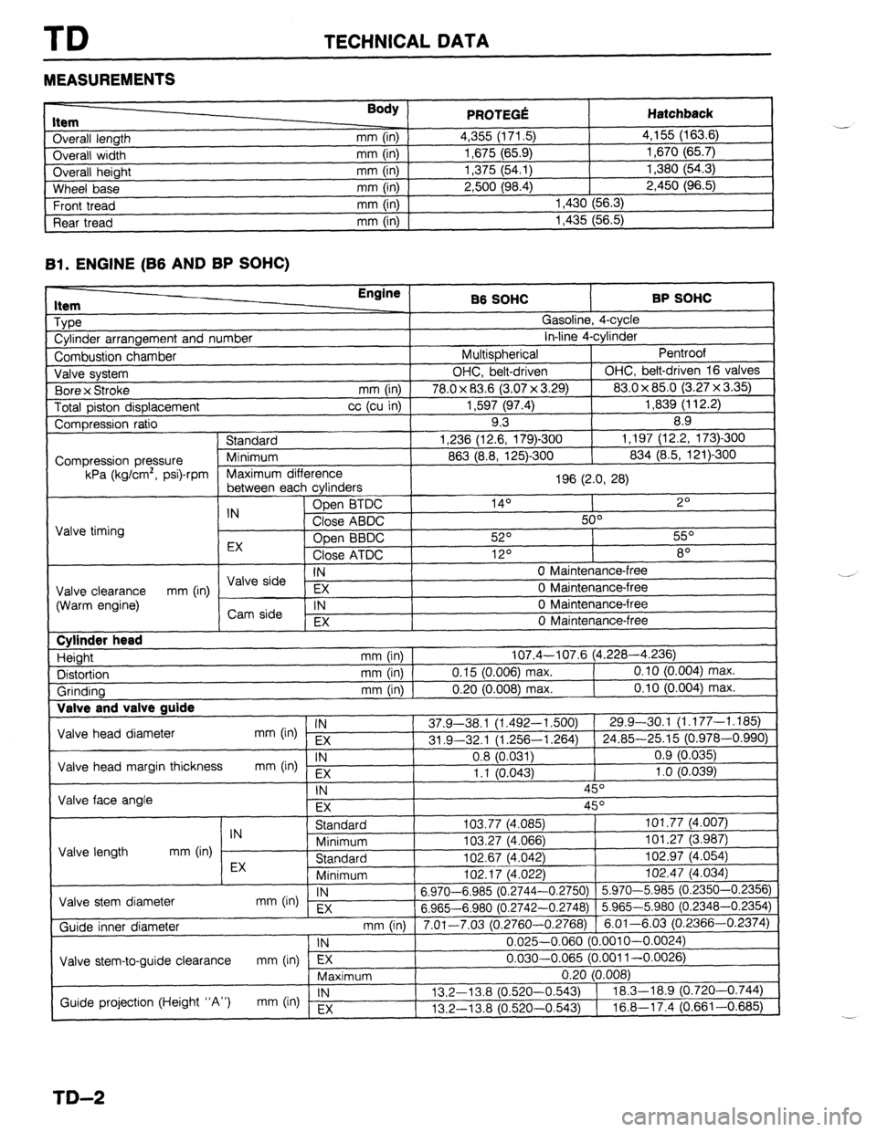
TD TECHNICAL DATA
MEASUREMENTS
I ._.____2_ nem
Overall length
Overall width
Overall height
Wheel base
Front tread
Rear tread Body ) mm (in)
mm (in)
mm (in)
mm (in)
mm (in)
mm (in) PRfWFr.f! . . ..s .-VW Hatchback 4,355 (171.5) 4,155 (163.6)
1,675 (65.9) 1,670 (65.7)
1,375 (54.1) 1,380 (54.3)
2,500 (98.4) 2,450 (96.5)
1,430 (56.3)
1,435 (56.5)
Bl. ENGINE (B6 AND BP SOHC)
1 Type
1 Cylinder arrangement and number Engine
86 SOHC BP SOHC
^ . . _
,?
I
uasollne, 4-cyw
. . *. 4
in-line 4-cyrinaer
Pentroof
1
I Combustion chamber I Multispherical
J Valve system OHC, belt-driven OHC, belt-driven 16 valves
. , I (3.07 x 3.29) 83.0 x 85.0 (3.27 x 3.35)
Total piston displacement cc (cu in) 1,597 (97.4) 1,839 (112.2)
Compression ratio 9.3 8.9
) Standard 1,236 (12.6, 179)-300 1,197 (12.2, 173)300
I
863 (8.8, 125)-300 834 (8.5, 121)300 1 Bore x Stroke
mm (in) I 78.0 x 83.6
Compression pressure
kPa (kg/cm’, psi)-rpm
E cvlinders 1 Maximum difference
196 (2.0, 28)
I
, ------- ---- -J - IN Open BTDC 14O 2O
Close ABDC 50°
Valve timing
Open BBDC 52O 55O
EX
Close ATDC 12O 8O
IN 0 Maintenance-free I \/AIo &-in --
Valve clearance EX 0 Maintenance-free
(Warm engine) mm (in) / ,,syi: 1
IN 0 Maintenance-free
I , EX 0 Maintenance-free
I Cylinder head
Height
Distortion
Grinding Valve and T _
Valve head diameter
Valve head margin thickness
Valve face angle IN mm (in) EX
IN
mm b-4 Fx mm (in) 107.4-107.6 (4.228-4.236)
mm (in) 0.15 (0.006) max. 0.10 (0.004) max.
mm (in) 0.20 (0.008) max. 0.10 (0.004) max.
37.9-38.1 (1.492-l ,500) 29.9-30.1 (1.177-1.185)
31 .Q-32.1 (1.256-l ,264) 24.85-25.15 (0.978-0.990)
0.8 (0.031) 0.9 (0.035)
1.1 10.043) 1 .o (0.039)
-, ,
\- I
IN 45O
EX 45O
I I Standard
IN
Minimum
Valve length mm (in)
EX Standard
Minimum I”L. I, \*.“cL
Valve stem diameter IN
mm On) EX 6.970-6.985 (0.2744-
6.965-6.980 (0.2742-
Guide inner diameter
I Valve stem-to-guide clearance mm (in) lTj7---- ,
Maximum 103.77 (4,085) 101.77 (4.007)
103.27 (4.066) 101.27 (3.987)
102.67 (4.042) 102.97 (4.054)
,n+ 47 IA noo
1 102.47 (4.034)
-0.2750) 5.970-5.985 (0.2350-0.2356)
-0.2748) 5.965-5.980 (0.2348-0.2354)
3.2760-0.2768) 6.01-6.03 (0.2366-0.2374)
0.025-0.060 (0.001 O-0.0024)
0.030-0.065 (0.001 l-0.0026)
-.
I
mm (in) 1 7.01-7.03 (r ‘
1 IN
Guide projection (Height “A”) IN
mm (in) Ex 13.2-l 3.8 (0.520-
13.2-13.8 (0.520-
TD-2
Page 1017 of 1164
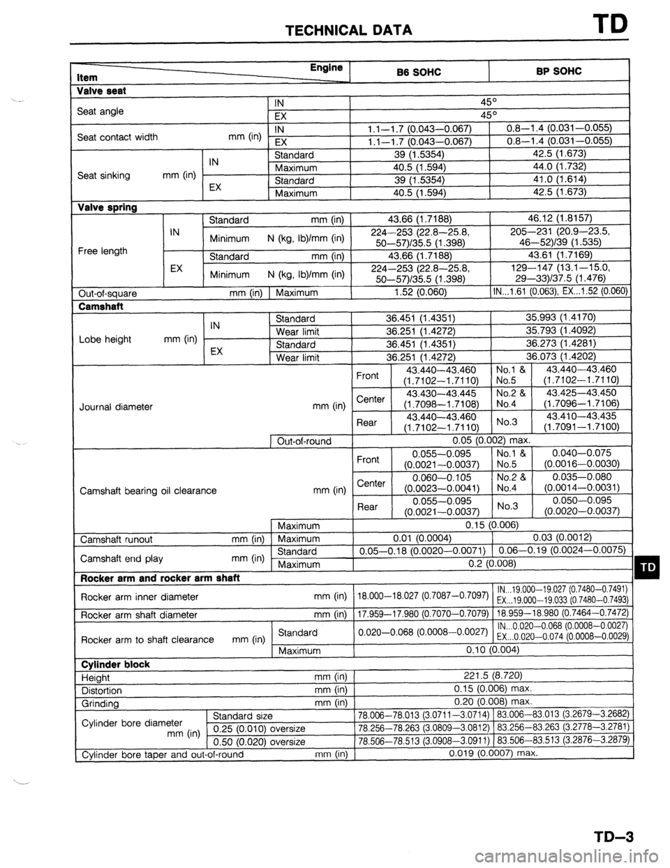
TECHNICAL DATA TD
Item Engine
B6 SOHC BP SOHC
Valve seat
IN
45O
Seat angle
EX 45O
Seat contact width IN
mm 04 EX 1.1-l .7 (0.043-0.067) 0.8-l .4 (0.031-0.055)
1.1-l .7 (0.043-0.067) 0.8-l .4 (0.031-0.055)
IN Standard 39 (1.5354) 42.5 (1.673)
Seat sinking mm (in) Maximum 40.5 (1.594) 44.0 (1.732)
EX Standard 39 (1.5354) 41.0 (1.614)
Maximum 40.5 (1.594) 42.5 (1.673) Valve spring
Standard mm (in) 43.66 (1.7188) 46.12 (1.8157)
IN
Minimum N (kg, Ib)/mm (in) 224-253 (22.8-25.8, 205-231 (20.9-4X3.5,
Free length 50--57)/35.5 (1.398) 46-52)/39 (1.535)
Standard mm (in) 43.66 (1.7188) 43.61 (1.7169)
EX
Minimum N (kg, Ib)/mm (in) 224-253 (22.8-25.8, 129-147 (13.1-15.0,
50-57)/35.5 (1.398) 29-33)/37.5 (1.476)
Out-of-square mm (in) 1 Maximum 1.52 (0.060) IN...l.61 (0.063) EX...1.52 (0.060)
Lobe height mm (in) IN
EX Standard 36.451 (1.4351) 35.993 (1.4170)
Wear limit 36.251 (1.4272) 35.793 (1.4092)
Standard 36.451 (1.4351) 36.273 (1.4281)
Wear limit 36.251 (1.4272) 36.073 (1.4202)
Front 43.440-43 ,460 No.1 & 43.440-43.460
(1.7102-l .7 ‘110) No.5 (1.7102-1.7110)
43.430-43 ,445 No.2 & 43.425-43.450
mm (in) Center
(1.7098-l .7 ‘108) No.4 (1.7096-l .7106)
. , L
Rear 43.440-43.460 No’3 43.41 o-43.435
(1.7102-l .7110) (1.7091-1.7100)
1 Out-of-round 0.05 (0.002) max.
Front 0.055-0.095 No.1 & 0.040-0.075
(0.0021-0.0037) No.5 (0.0016-0.0030)
e--I-.. 0.060-O. 105 No.2 84 0.035-0.080
1041) No.4
“.“-.-..“” (O.OOi 4-0.0031)
Rear 0.055-0.095 0.050-0.095
(0.0021-0.0037) No.3
(0.0020-0.0037)
1 Maximum
0.15 (0.006)
0.01 (0.0004)
0.03 (0.0012)
0.05-0.18 (0.0020-0.0071) 0.06-0.19 (0.0024-0.0075)
n ‘1 m *no Journal diameter
Camshaft hearinn nil cIewanr.F? mm tin I b,er’Ler I (0.0023--0.c
Camshaft runout mm (in) Maximum
Camshaft end play mm (in) Standard
Maximum
I Rocker arm and rocker arm shaft
Rocker arm inner diameter mm (in) 18.000-18.027 (
Rocker arm shaft diameter mm (in)
17 9.59-17 981) I “.L ~“.““O,
lN...19.000--19.027 (0.7480-0.7491)
o.7087-o’70g7) EX...19.000-19.033 (0.7480-0.7493)
I .““” -- -
0 7070-0.7079) 18.959-18.980 (0.7464-0.7472)
lN...0.020-0.068 (0.0008-0.0027)
Rnrkx arm tn shaft clearance
mm (in Standard
I .Y”,.VG 11.,, .” -,,-.. “,“-.“, .I”
““” ,“‘I o.020-o.068 (“~ooo8-o~oo27) EX...O.020-0.074 (0.0008-0.0029)
Maximum 0.10 (0.004) Cylinder block
Height mm (in) 221.5 (8.720)
Distortion mm (in) 0.15 (0.006) max.
Grinding mm (in) 0.20 (0.008) max.
^. , ,
78.006-78.013 (3.0711-3.0714) 183.006-83.013 (3.2679-3.2682)
-.n nr,. -,n fin,% ,n nnnr
” nn’n’ ’ “- T)cc 83.263 (3.2778-3.2781) Cylinder bore diameter stanaara size
mm (in) 0.25 (0.010) oversize IU.L3cl-/U.dDJ (J.uouu-J.uo IL) 1 OJ.LJU--
0.50 (0.020) oversize 78.506-78.513 (3.0908-3.0911) ) 83.506-
Cylinder bore taper and out-of-round mm (in) 0.019 (0.0007) ma: 83.513 i3.2876-3.2879)
I(.
TD-3
Page 1018 of 1164
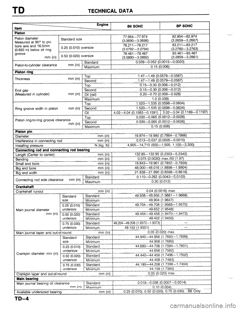
TD TECHNICAL DATA
I-
Item Enainc , 66 SOHC BP SOHC
Piston
, 1
-97 n-1 7-7 /t-r”
82.954-82.974
I -’
Piston diameter
Standard size I I I.Y34--1 l.YlG + I,-. nnnn
n r,Prx< > Measured at 90’ to pin (J.uoYY-mJoYo) (3.2659-3.2667)
bore axis and 165mm
I 78.211-78.217 83.211-83.217
(0.650 in) below oil ring 0.25 (0.010) oversize
(3.0792-3.0794) (3.2760-3.2763)
groove
0.50 (0.020) oversize 78.461-78.467 83.461-83.467
mm (in)
(3.0890-3.0892) (3.2859-3.2861)
Piston-to-cylinder clearance mm (in) Standard 0.039-0.052 (0.0015-0.0020)
Maximum 0.15 (0.006) Piston ring
Thickness
End gap
(Measured in cylinder) mm (in) Top
Second
Top
Second
mm (in) Oil (rail) I 1.47-l .49 (0.0579-0.05E
1.47-l .49 (0.0579-0.05E
0.15-0.30 (0.006-0.01~
0.15-0.30 (0.006-0.01; I Connectina rod and connectin
‘I ‘I 0.20-0.70 (0.008-0.028) 0.20-0.70 (0.008-0.028)
Maximum 1 .o (0.039) 1 .o (0.039)
Top 1,520-l ,535 (0.0598-0.0604) 1,520-l ,535 (0.0598-0.0604)
Ring groove width in piston
mm (in) Second 1.520-l ,535 (0.0598-0.0604) 1.520-l ,535 (0.0598-0.0604)
Oil
d d 117-4 04 (0 1583-O 1591) f ‘.02-3.04 (0.1189-0.1197) 117-4 04 ..“_ ..“. (0 1583-O 1591) f 1.02-3.04 (0.1189-0.1197)
\-“--- -’ - I
Piston ring-to-ring groove clearance Top 0.030-0.065 (O.O( 312-0.0026)
mm (in) Second 0.030-0.065 (O.O( 312-0.0026)
I
( Maximum
0 15 [email protected]) Piston pin
Diameter u,a, I KaEil mm (in) 1 111111 ,888, 19.974-19.980 (0.7864-0.7866) .“.“. _.__ J (0.7864-0.7866)
Interference in connecting rod ‘(0.0005-0.0015)
mm (In) 1 0.013-0.037 (0.0005-0.0015)
lnstallina pressure
N (kg, lb) 1 4,90614,715 (500-l ,500, 1 ,l oo-3,300) 4,90614,715 (500-l ,500, 1 ,l oo-3,300)
Length (Ceiter to center) Length (Ceiter to center) lg rod bearing lg rod bearing
mm (in) 1 mm (in) 1 132.85-132.95 (5.2303-5.2342) 132.85-132.95 (5.2303-5.2342)
Bending Bending mm (in) 1 mm (in) 1 0.075 (0.0030) max./50 (1.97) 0.075 (0.0030) max./50 (1.97)
Small end bore mm (in) 19.943-19.961 (0.; ‘852-0.7859) ‘852-0.7859)
Big end bore
mm (in) 48.000-48.016 (1 .f 3898-l .8904) 3898-l .8904)
Big end width mm (in) 21.838-21.890 f0.f 3598-0.8618)
I Connecting rod side clearance mm (in) Standard
! 0.11 O-O.262 (0.0043-0.0103)
Maximum 0.30 (0.012) Crankshaft
Crankshaft runout
mm (in) 0.04 (0.0016) max.
Standard Standard 49.938-49.956 (1.9661-I .9668)
size
Minimum 49.904 (1.9647)
0.25 (0.010) Standard 49.704-49.708 (1.9568-l .9570)
Main journal diameter undersize
Minimum 49.652 (1.9548)
mm (in)
0.50 (0.020) Standard 49.454-49.458 (1.9470-l .9472)
undersize
Minimum 49.402 (1.9450)
0.75 (0.030) Standard 49.204-49.208 (1.9372-I .9373) 1 -
undersize
Minimum 49.152 (1.9351) -
~.. Crankshaft
3598-0.8618j 1
I 0.11 O-O.262 (0.0043-0.0103)
0.30 (0.012)
1 Main iournal taoer and out-of-round
mm (in) I 0.05 (0.020) max.
Standard Standard 44.940-44.956 (i.7693-1.7699)
size
Minimum 44.908 (1.7680)
0.25 (0.010) Standard 44.690-44.706 (1.7594-l .7601)
undersize
Crankpin diameter mm (in) Minimum 44.658 (1.7582)
0.50 (0.020) Standard 44.440-44.456 (1.7496-I .7502)
undersize
Minimum 44.408 (1.7483)
0.75 (0.030) Standard 44.190-44.206 (1.7398-l .7404)
undersize
Minimum 44.158 (1.7385)
0.05 (0.020) max.
b
I I , I - \“‘---I 0.05 (0.020) max.
b
I I Crankuin taper and out-of-round
mm (In) I Main bearing
I
Main journal bearing oil clearance Standard
I 0.018-0.036 (0.0
mn-, ,i” .A- :-- -
c-l*,- ‘^’
Available undersized bearing
TD-4
007-0.0014)
I& II I I \” ‘,
, I”ld*llT,UIr1
I “. I J (U.004)
mm (in) 0.25 (O.OlO), 0.50 (0.020) 0.75 (0.030) . . . 86 Otily
Page 1019 of 1164
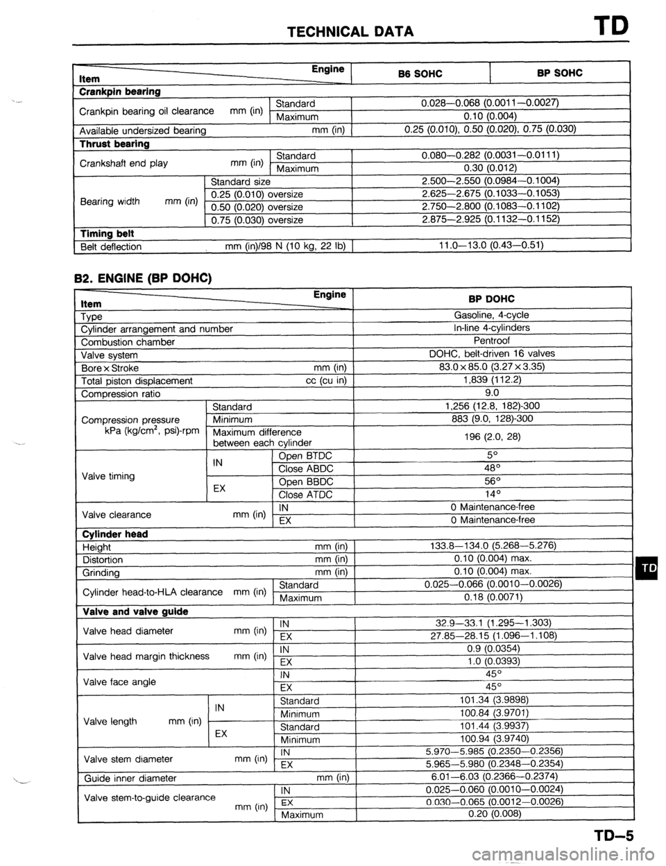
TECHNICAL DATA TD
r-
RP sm.lc: I Item
Crankpin bearing Engine
86 SOHC
I -. VW.._
Crankpin bearing oil clearance mm (in) Standard 0.028-0.068 (0.001 l-0.0027)
Maximum 0.10 (0.004)
Available undersized bearing mm (in)
0.25 (O.OlO), 0.50 (0.020) 0.75 (0.030) Thrust bearing
Crankshaft end play mm (in) Standard 0.080-0.282 (0.0031-0.0111)
Maximum 0.30 (0.012)
Standard size 2.500-2.550 (0.0984-0.1004)
Bearing width mm (in) 0.25 (0.010) oversize 2.625-2.675 (0.1033-0.1053)
0.50 (0.020) oversize 2.750-2.800 (0.1083-0.1102)
0.75 (0.030) oversize 2.875-2.925 (0.1132-0.1152)
1 Timing belt
Belt deflection mm (in)/98 N (10 kg, 22 lb) 1 11 .o-13.0 (0.43-0.51) 82.
ENGINE (BP DOHC) Item
Type
Cylinder arrangement and number BP DOHC
Gasoline, 4-cycle
In-line 4-cylinders
-. I
Combustion chamber
Valve svstem DOHC, belt-d
Bore x Stroke
Total piston displacement ventroot
riven
(3.2:
mm (in) 1 83.0 x 85.0
cc (cu in) ]
7x3.35)1 1,839 (112.2)
I 16 valves I 9.0
-300
mn Compression ratio
Standard 1,256 (12.8, 182)
Compression pressure Minimum 883 (9.0, 128)-Z kPa (kglcm2,
Psi)-rPm
Maximum dif
‘ference
between eat -, h cvlinder 196 (2.0, 28)
IN Open BTDC 5O
Valve timing Close ABDC 48’
EX Open BBDC 56O
Close ATDC .4 In
IY-
IN
mm (in) EX 0 Maintenance-l
Valve clearance
0 Maintenance-i ‘ree
‘me Cylinder head
Height mm (in)
Distortion mm (in)
Grinding mm (in)
Standard
Cylinder head-to-HLA clearance mm (in) Maximum Valve and valve guide 133.8-134.0 (5.268-5.276)
0.10 (0.004) max.
0.10 (0.004) max.
0.025-0.066 (0.0010-0.0026)
0.18 (0.0071)
Valve head diameter IN
mm (in) EX 32.9-33,l (1.295-l ,303)
27.85-28.15 (1.096-1.108)
Valve head margin thickness IN
mm On) Fx 0.9 (0.0354)
1 .o fO.0393)
1 Valve face angle . .
I
FX I I
Valve length IN
Standard 101.34 (3.9898)
mm (in) Minimum 100.84 (3.9701)
Standard 101.44 (3.9937) I -, .
I
Valve stem diameter EX
Minimum loo.94 i3.974oj
IN
mm (in) - EX 5.970-5.985 (0.2350-0.2356)
5.965-5.980 (0.2348-0.2354)
mm (in) I
. , , 6.01-6.03 (0.23 166-0.2374)
1 IN
I 0.025-0.060 (0.0010-0.0024)
3.0012-0.0026)
( Maximum 0.20 (0.008)
I
TD-5
Page 1020 of 1164
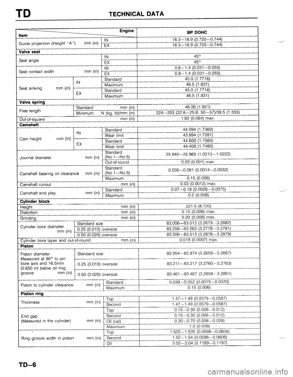
TD TECHNICAL DATA
Item Engine
BP DOHC
Guide projection (Height “A”) IN
mm (in) EX 18.3-l 8.9 (0.720-0.744)
_-j
18.3-l 8.9 (0.720-0.744)
Valve seat
Seat angle
Seat contact width IN 45O
EX 45O
IN
mm (in) EX 0.8-l .4 (0.031-0.055)
0.8-l .4 (0.031-0.055)
Seat sinking
Valve spring
Free length
Out-of-square
Camshaft IN Standard 45.0 (1.7716)
mm (in) Maximum 46.5 (1.831)
EX Standard 45.0 (1.7716)
Maximum 46.5 (1.831)
Standard mm (in) 46.26 (1.821)
Minimum N (kg, Ib)/mm (in) 224-253 (22.8-25.8, 50--57)/39.5 (1.555)
mm (in) 1.62 (0.064) max.
I C+^~rl^.A
44.094 (1.7360)
43.894 (1.7281)
44.600 (1.7560)
44.400 (1.7480) IN 3Ldl l”dl u
Cam height mm (in) Wear limit
EX Standard
Wear limit
Standard
Journal diameter mm (in) (No.l-No.5) 25.940-25.965 (1.0213-l .0222)
Out-of-round 0.03 (0.001) max.
Standard
Camshaft bearing oil clearance mm (in) (No-1-No.5) 0.035-0.081 (0.0014-0.0032)
Maximum 0.15 (0.006)
Camshaft runout mm (in) 0.03 (0.0012) ma
IX.
Camshaft end play mm (in) ’ Standard 0.07-O. 19 (0.0028-0.0075)
Maximum I
I n 9 m mm “.L \“.“““,
Cylinder block
Height
Distortion
Grinding mm (in) 221.5 (8.720)
mm (in) 0.15 (0.006) max.
mm (in) 0.20 (0.008) max.
Cylinder bore diameter Standard size 83.006-83.013 (3.2679-3.2682)
mm (in) 0.25 (0.010) c oversize 83.256-83.263 (3.2778-3.2781)
n.vl IO0701 I -.--
\-----I Jversize 83.506-83.513 (3.2876-3.2879)
Cylinder bore taper and out-of-round mm (in) 0.019 (0.0007) max.
Piston
I
I I
Piston diameter 82.954-82.974 (3.2659-3.2667)
Measured at 90” to pin
bore axis and 16.5mm
83.21 l-83.21 7 (3.2760-3.2763)
(0.650 in) below oil ring
groove
mm fin) 0.50 (0.020) oversize 83.461-83.467 (3.2859-3.2861)
r~ Piston to cylinder clearance
mm On) (Standaid 0.039-0.052 (0.0015-0.0020)
Piston ring
Thickness
End gap
(Measured in the cylinder) mm (in) ‘W
Second
Top
Second
mm (in) Oil (rail)
Maximum
Too I .‘t, - I .ct3 (“.“a, 3-u
1.47-l .49 (0.0579-C
0.1%0:30 (0.006--C
0.15-0.30 (0.006-C
I I.01 2)
0.20-0.70 (0.008-0.028)
1.0 (0.039)
1,520-l
,535 (0.0598-0.0604)
1.52-l .54 (0.0598-0.0606)
3.02-3.04 (0.1189-O. 1197)
I Ring groove width in piston mm (In) n
;_A
TD-6
Page 1024 of 1164
TD TECHNICAL DATA
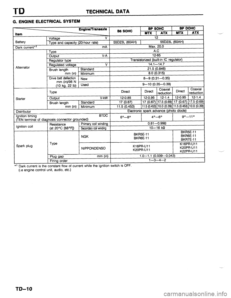
G. ENGINE ELECTRICAL SYSTEM
3attery Dark
current*’
Alternator 86 SOHC BP SOHC
I BP DOHC
MTX 1 ATX 1 MTX 1 ATX
Voltage V 12
Type and capacity (20-hour rate) 55D23L (60AH) 1 55D23L (60AH)
mA Max. 20.0
Type A.C
output V-A 12-65
Regulator type Transistorized (built-in IC regulator)
Regulated voltage V 14.1-14.7
Brush length Standard 21.5 (0.846)
mm (in) Minimum 8.0 (0.315)
Drive belt deflection
New 8-Q (0.31-0.35)
;riL’F,i Used Q-10 (0.35-0.39)
Coaxial
Type Direct Direct Coaxial
reduction Direct
reductior
Starter output V-kW 12-0.85 12-0.95 12-1.4 12-0.95 12-1.4
Brush length Standard 17 (0.67) 17 (0.67) 17.5 (0.69) 17 (0.67) 17.5 (0.69
mm (in) Minimum 11.5 (0.453) 11.5 (0.453) 10.0 (0.39) 11.5 (0.453) 10.0 (0.39
Distributor Electronic spark advance (photo diode)
Ignition timing BTDC
(TEN terminal of diagnosis connector grounded) 6O-8O 4O-6O 9”-11 O
Ignition coil Resistance Primary coil winding 0.81 -O.QQg
(at 20% [68OF]) Secondary coil winding lo-16 kg
SK&E-1 1 BKR5E-11
NGK
BKRGE-11 BKRGE-11
BKR7E-11
Spark plug Type
NIPPONDENSO KlGPR-Ull
K20PRUll KlGPR-Ull
K20PRUll
K22PRUll *:
. Plug gap
Firing order mm (in) 1.0-l .l (0.039-0.043)
l-3-4-2
---
’ Dark current is the constant flow of current while the ignition switch IS UFF.
(i.e engine control unit, audio, etc.) ..-
._*
T&l 0