1992 MAZDA PROTEGE fuel filter
[x] Cancel search: fuel filterPage 390 of 1164

F FUEL SYSTEM
MIN. 35mm (1..4 in) -/
23UOFX-10
NJ
23UOFX-l(
OBUOFX-1:
Installation Note
Fuel hoses
1. Push the ends of the main fuel hose, fuel return hose, and
evaporative hoses onto the fuel tank fittings at least 25mm
(1.0 in).
2. Push the fuel filler hose onto the fuel tank pipe and filler pipe
at least 35mm (1.4 in).
FUEL FILTER
Replacement
Low-pressure side (In-tank filter)
(Refer to page F-128.)
High-pressure side
The fuel filter must be replaced at the intervals outlined in the
maintenance schedule.
Warning
l Always work away from sparks or open flames.
1. Disconnect the fuel hoses from the fuel filter.
2. Remove the fuel filter and bracket.
3. Install in the reverse order of removal.
Note
l When installing the filter, push the fuel hoses fully
onto the fuel filter.
F-l 24
Page 394 of 1164

F FUELSYSTEM
Disassembly / Assembly
1. Disassemble in the order shown in the figure.
2. Assemble in the reverse order of disassembly, referring to
Assembly Note
1. Band
2. Bracket
3. Rubber mount
OSUOFX-152
4. Fuel pump
Assembly note ,..........,....,,....,.. page F-l 28
5. Fuel filter
Assembly note
O-ring set
1. Use a new O-ring set. (O-ring, cap, and spacer)
2. Apply oil or fuel to the O-ring set before installing.
3. To confirm sealing of the O-ring, blow air through the main
pipe after assembling the fuel pump and fuel tank gauge
sender unit, and verify that no air flows past the O-ring. If
air flows through the pump, the check ball may be stuck.
Shake the fuel pump two or three times and recheck.
Fuel pump
1. After installing the fuel pump to the bracket, pull the pump
down so that it is tight against the bracket.
F-l 28
Page 395 of 1164

FUEL SYSTEM F
STA
OBUOFX- 15
03UOFX-15
DISCONNECT CONNECTOR
TO RELEASE FUfL PRESSURE
REAR SEAT C
23UOFX-11
INSTALL CLAMPS
CIRCUIT OPENING RELAY
Inspection
Voltage inspection
I, Check voltage between the following terminals and a ground
using a voltmeter.
Ve: Battery voltage
Resistance inspection
1, Check resistance between the terminals using an ohmmeter.
Terminal Resistance (Q)
STA-El 21-43
B-Fc 109-226
B-Fp 00
Replacement
1, Remove the passenger side wall.
2. Disconnect the relay connector.
3. Remove the relay from ECU bracket.
4. Install in the reverse order of removal.
PRESSURE REGULATOR
Inspection
Fuel line pressure
Warning
l Before performing the following operation, release
the fuel pressure from the fuel system to reduce the
possibility of injury or fire. (Refer to page F-121.)
1, Disconnect the negative battery terminal.
2. Connect a fuel pressure gauge between the fuel filter and
the fuel main hose. (Install clamps as shown.)
3. Connect the negative battery terminal.
4. Start the engine and run it at idle.
5. Measure the fuel line pressure.
Fuel line pressure:
206-255 kPa (2.1-2.6 kg/cm2, 30-37 psi)
6. Disconnect the vacuum hose from the pressure regulator
and measure the fuel line pressure.
Fuel line pressure:
265-314 kPa (2.7-3.2 kg/cm2, 36-46 psi)
F-l 29
03UOFX-157
Page 396 of 1164

F FUELSYSTEM
DISCONNECT CONNECTOR
TO RELEASE FlJ$L PRESSURE
REAR SEAT C
23UOFX-11
INSTALL CLAMPS 7
03UOFX.I 59
F-l 30
DIAGNOSl&OJNECTOR
/ K
1 SUOFX-10
DISCONNECT CONNECTOR
TO RELEASE
FlJl$L PRESSURE
23UOFX-11
I
Hold pressure
Perform this inspection if the fuel pressure hold inspection is
not as specified. (Refer to page F-121 .)
Warning
l Before performing the following operation, release
the fuel pressure from the fuel system to reduce the
possibility of injury or fire. (Refer to page F-121 .) ,-
1. Disconnect the negative battery terminal.
2. Connect a fuel pressure gauge between the fuel filter and
the fuel main hose. (Install clamps as shown.)
3. Connect the negative battery terminal.
4. Connect the diagnosis connector terminals
F/P and GND
with a jumper wire.
5. Turn the ignition switch ON
for 10 seconds to operate the
fuel pump.
6. Turn the ignition switch OFF and disconnect the jumper wire.
7. Pinch the fuel return hose with pliers.
8. Observe the fuel pressure
for 5 minutes.
Fuel pressure:
More than 147 kPa (1.5 kg/cm2, 21 psi)
9. If not as specified, replace the pressure regulator.
Replacement
Warning
l Before performing the followlng operation, release
the fuel pressure from the fuel system to reduce the
possibility of injury or flre. (Refer to page F-l 21.)
l When replacing fuel system components, keep
sparks, cigarettes, and open flames away from the
fuel.
1. Disconnect the vacuum hose.
2. Disconnect the fuel return hose.
3. Remove the pressure regulator.
Tightening torque:
7.8-11 N#m (80-110 cm-kg, 89-95 In-lb)
4. Install a new O-ring.
5. Install in the reverse order of removal.
Page 953 of 1164

AUDIO T
Noise Suppression Chart
Cause
‘uel pump noise Remedy Move speaker wiring away from fuel pump wire.
REAR HARNESS FUEL
PUMP
Wotor noise
Wiper, washer, power
window, for example) 1. Check grounding.
2. Install condensers to motor circuit.
Turn signal noise Connect condenser (0.5 pF) to power line of filter unit. Note
CONDENSER
4lternator noise
l Condenser should be placed near flasher unit.
Connect condenser (0.5 pF) near alternator.
TO RADIO
CONDENSER
97UOTX-1
T-97
Page 1023 of 1164

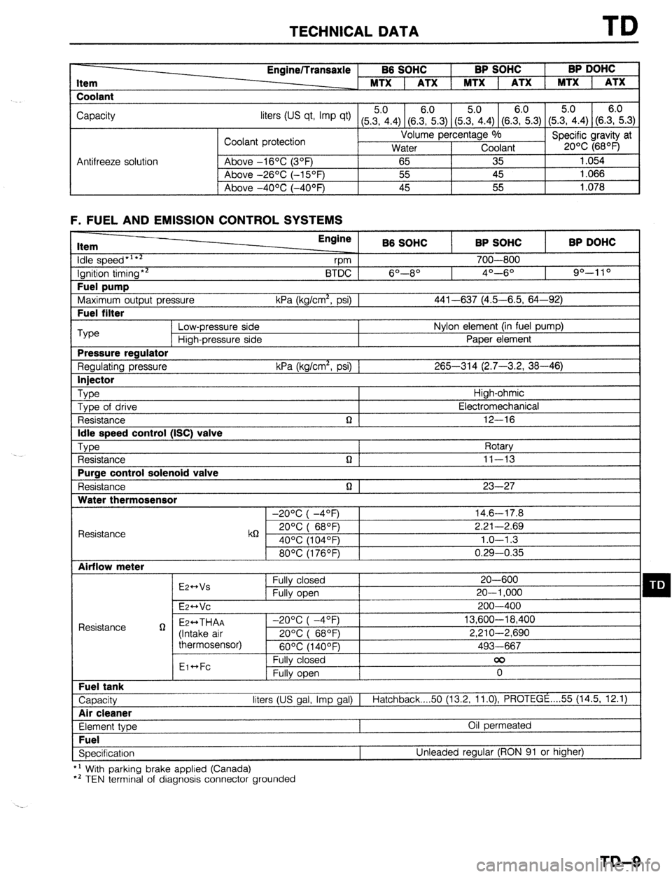
TECHNICAL DATA TD
Item
Coolant Engine/Transaxle B6 SOHC BP SOHC BP DOHC
MTX 1 ATX 1 MTX 1 ATX 1 MTX 1 ATX
Capacity
liters tus qt, Imp qt) (5Z.4) (8.E.3) (5&4) (SE.3) (5.?i.4) (S.E.3)
Coolant protection Volume percentage %
Specific gravity at
Water Coolant 20% (68OF)
Antifreeze solution Above -16OC (3OF)
65 35 1.054
Above -26OC (-15OF) 55 45 1.066
I Above -4OOC (-40°F) 45 55
1.078
F. FUEL AND EMISSION CONTROL SYSTEMS Item
idle speed*‘**
Ignition timing** Fuel pump
Maximum output pressure Fuel filter Engine
B6 SOHC BP SOHC BP DOHC
vm 700-800
BTDC 6O--8O 4O---6O 90-l 10
kPa (kg/cm*, psi) 1 441-637 (4.5-6.5, 64-92) ‘Type
Low-pressure side Nylon element (in fuel pump)
High-pressure side Paper element Pressure regulator
Regulating pressure kPa (kg/cm*, psi) 1 265-314 (2.7-3.2, 38-46) Injector
Type
High-ohmic
Type of drive Electromechanical
Resistance n 12-16 Idle speed control (ISC) valve
Type
Rotary
Resistance n ] 11-13 Purge control solenoid valve
Resistance n 1 23-27 Water thermosensor
-20°C( -4OF) 14.6-17.8
Resistance k6 20°C( 68QF) 2.21-2.69
40% (104OF) 1.0-l .3
80°C(1760F) 0.29-0.35 Airflow meter
E2++Vs Fully closed 20-600 q D Fully open 20-l ,000
E~HVC 200-400
Resistance g Ez++THAA -2O%(-4OF) 13,600-18,400
(Intake air 20%( 68OF) 2,210-2,690
thermosensor)
60°C(1400F) 493-667
Eic*Fc Fully closed 00
Fully open 0 Fuel tank
Capacity liters (US gal, Imp gal) I
Hatchback 50 (13.2, 11.0) PROTEGE . . . . 55 (14.5, 12.1) Air cleaner
Element type Oil permeated Fuel
Specification Unleaded regular (RON 91 or higher)
*’ With parking brake applied (Canada)
*’ TEN terminal of diagnosis connector grounded
TD-9
Page 1050 of 1164

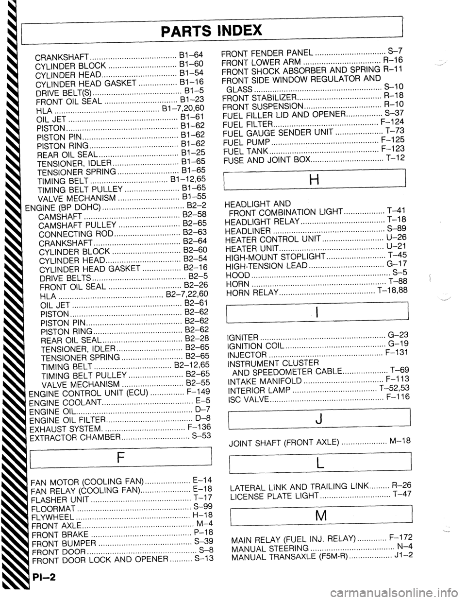
PARTS INDEX
I
CRANKSHAFT.. ....................................
I31 -64
CYLINDER BLOCK .............................. 61-60
CYLINDER HEAD..
............................... 81-54
CYLINDER HEAD GASKET .................
Bl-16
DRIVE BELT(S). ...................................... 81-5
FRONT OIL SEAL ................................ 81-23
HLA .............................................. Bl-7,20,60
OIL JET ................................................ 81-61
PISTON.. ...............................................
Bl-62
PISTON PIN..
........................................ 81-62
PISTON RING
....................................... 81-62
REAR
OIL SEAL..
................................. 81-25
TENSIONER, IDLER ............................. Bl-65
TENSIONER
SPRING ...........................
Bl-65
TIMING BELT ..................................
Bl-12,65
TIMING BELT PULLEY ........................
Bl-65
VALVE MECHANISM ........................... Bl-55
ENGINE
(BP DOHC) .................................... B2-2
CAMSHAFT ..........................................
82-58
CAMSHAFT PULLEY ...........................
B2-65
CONNECTING ROD..
........................... 82-63
CRANKSHAFT ......................................
B2-64
CYLINDER BLOCK ..............................
82-60
CYLINDER
HEAD.. ............................... B2-54
CYLINDER HEAD GASKET .................
82-16
DRIVE
BELTS.. .......................................
B2-5
FRONT
OIL SEAL ................................
82-26
H LA ..............................................
OIL JET .......................... B2-7iyL;;
......................
PISTON .................................................
B2-62
PISTON PIN ..........................................
82-62
PISTON RING..
..................................... 82-62
REAR OIL SEAL ................................... B2-28
TENSIONER, IDLER ............................. B2-65
TENSIONER SPRING ........................... B2-65
TIMING
BELT.. ................................
B2-12,65
TIMING BELT PULLEY ........................ 82-65
VALVE MECHANISM ........................... 82-55
ENGINE CONTROL UNIT (ECU) ............... F-149
ENGINE COOLANT
........................................ E-5
ENGINE OIL.. .................................................
D-7
ENGINE OIL FILTER.. .................................... D-8
’ EXHAUST SYSTEM. ...................................
F-136
EXTRACTOR CHAMBER .............................. S-53
F
FAN MOTOR (COOLING FAN). ................... E-14
FAN RELAY (COOLING FAN). ..................... E-18
FLASHER UNIT ............................................
T-17
FLOORMAT ..................................................
S-99
FLYWHEEL ..................................................
H-18
FRONT AXLE .................................................
M-4
FRONT BRAKE ............................................
P-l 8
FRONT BUMPER ......................................... S-39
FRONT DOOR ................................................
S-8
FRONT DOOR LOCK AND OPENER ..........
S-13
PI-2
FRONT FENDER PANEL ............................... S-7
FRONT LOWER ARM .................................. R-16
FRONT SHOCK ABSORBER AND SPRING R-11
FRONT SIDE WINDOW REGULATOR AND
GLASS ........................................................ S-10
FRONT STABILIZER..
................................... R-l 8
FRONT SUSPENSION .................................. R-l 0
FUEL FILLER LID AND OPENER..
.............. S-37
FUEL FILTER .............................................. F-l 24
FUEL GAUGE SENDER UNIT ..................... T-73
FUEL PUMP ............................................... F-125
FUEL TANK
................................................ F-123
FUSE AND JOINT BOX.. .............................. T-12
H
HEADLIGHT AND
FRONT COMBINATION LIGHT..
................ T-41
HEADLIGHT RELAY ..................................... T-l 8
HEADLINER ................................................. S-89
HEATER CONTROL UNIT.. ......................... U-26
HEATER UNIT
.............................................. U-21
HIGH-MOUNT STOPLIGHT
.......................... T-45
HIGH-TENSION LEAD ................................. G-l 7
HOOD ............................................................. S-5
HORN T-88
...........................................................
HORN RELAY
.......................................... T-18,88
.__. ’
I I
IGNITER .......................................................
G-23
IGNITION COIL.. .......................................... G-19
INJECTOR .................................................. F-l 31
INSTRUMENT CLUSTER
AND SPEEDOMETER CABLE
.................... T-69
INTAKE MANIFOLD ................................... F-113
INTERIOR LAMP ..................................... T-52,53
ISC VALVE.. ................................................ F-l 16
J
JOINT SHAFT (FRONT AXLE) .................... M-18
L
LATERAL LINK AND TRAILING LINK.. ....... R-26
LICENSE PLATE LIGHT.. ............................. T-47
i
M
I
---
MAIN RELAY (FUEL INJ. RELAY). ............ F-172
MANUAL STEERING ..................................... N-4
MANUAL TRANSAXLE (F5M-R). .................. Jl-2