Page 1101 of 1164
HARNESS COLOR : FRONT- ENGINE m WIRING UlACjl-iAM L
I
B
l-4 -I
FUSE BOX
!it% FAN
RELAY NO.1
FUSE BOX
JOINT BOX
Page 1106 of 1164
WIRINQ DIAQRAM
‘1Tt-i WINDSHIELD II.. . PROTEGE
RUISE CONTROL ‘WIPER 6; WASHER D-2
B (El BOA
\
&fJq
L (F)
j---W (F)
-----j-ER (F) -//LI
01:
[
01:
L/( WINDSHIELD
i (F)
I - I
f3 iF)
WINDSHIELD (5
I ;;;;;“I”‘”
MOTOR
6 (F)
v (
-01 WINDSHIELD WIPER E; WASHER SWITCH (F) D-02 WINDSHIEt-“oT~~~~~ I-03 WINDSHIELD
(ASHER MOTOR (F) MAIN
-04 WINDSHIELD WIPER RELAY (F)
f3 L/Y G/Y L/W R
BR L/O L w G/W 1.
Et 0 B
w L/O
Page 1114 of 1164
ZANADA l DAYTIME RUNNING LIGHTS E-3
DRL CONTROL UNIT
-07 DRL RELAY (F) E-08 DRL RESISTOR (F) E-09 DRL CONTROL UNIT (F)
a
Page 1125 of 1164
-I G JOINT BOX
JB-06
A/C SWITCH
^ 1^
CONDENSER FAN RELAY
G-02 AK REtAY
G-08 0
//. /
HARNESS COLOR : FRONT m ENGINE m INSTRUMENT PANEL WIRING DIAGRAM 2
r
RESlSTOR
ASSEMBLY
G-14
6 BLOWER SWITCH
--Km
CONDENSER
FAN ;$$&A,, v\u\.,
SWlTCH NO 2
G:Ol
FUSE BOX
'!
G-05
REFRIGERANT
PRESSURE
SWITCH No 1
p-ciGJ MAIN FUSE
G-13
FUSE BOX
. G-03
DIODE
THERMOSWITCH
G-12 BLOWER
MOTOR
I
JOINT BOX
E
(BLUE)
Z-69
Page 1140 of 1164
, WIRINU VIAUI’IAM
l POWER DOOR LOCK K-2
,----PPROTEGf;----
:-09 POWER DOOR LOCK SWITCH(DR1) K-10 POWER DOOR LOCK K-11 POWER DOOR LOCK MOT’X#
RELAY (F)
(3HB) (PROTEGE)
(3HB)
(PROTEGE)
:-I2 POWER DOOR LOCK K-13 POWER DOOR LOCK
MOTOR RL (DR3) MOTOR RR (DR4)
Z-84
Page 1144 of 1164
. WININU uwwanmm
GLIDING SUNROOF M
1-01 SLIDING SUNtWl; M-02 SLIDING S&tW~; M-03 SLIDING SU;;?;; M-04 SLIDING SUNROOF
RELAY
B mi r-r=
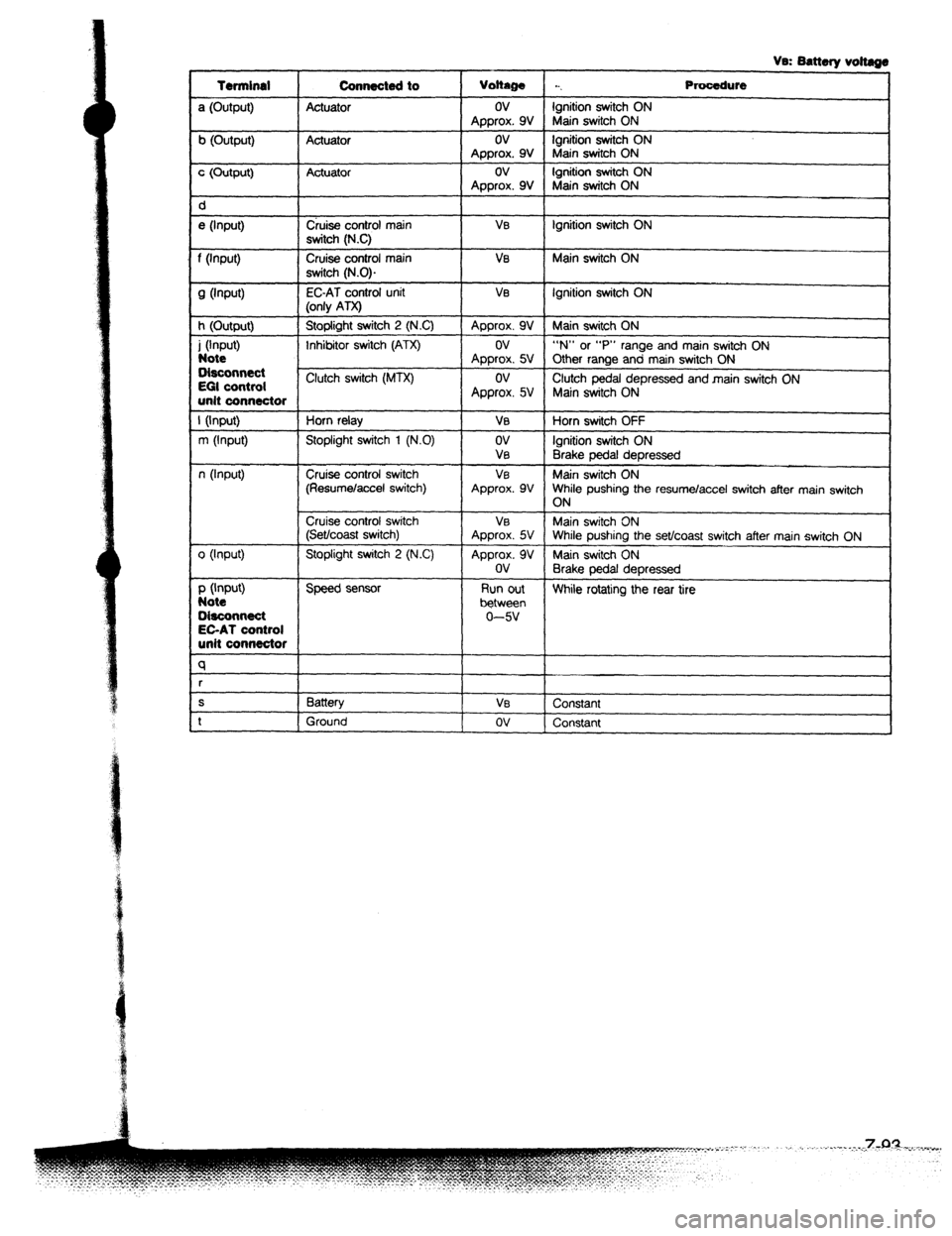
Page 1149 of 1164

Vs: Battery voltags
Terminal Connecte4t to
Voltage . . . Procedure
a (Output) Actuator ov Ignition switch ON
Approx. 9V Main switch ON
b (Output) Actuator ov Ignition switch ON
Approx. 9V Main switch ON
c (Output) Actuator ov Ignition switch ON
Approx. 9V Main switch ON
d
e (Input) Cruise control main VEI Ignition switch ON
switch (N.C)
f (input) Cruise control main Ve Main switch ON
switch (N.0).
9 Wwft) EC-AT control unit VI3 Ignition switch ON
(only ATX)
h (Output) Stoplight switch 2 (NC) Approx. 9V Main switch ON
i (Input) Inhibitor switch (ATX) ov “N” or “P” range and main switch ON
Note Approx. 5V Other range and main switch ON
Disconnect
EGI control Clutch switch (MTX) ov
Clutch pedal depressed and main switch ON
unit connector Approx. 5V Main switch ON
I (Input) Horn relay VB Horn switch OFF
m (Input) Stoplight switch 1 (N.0) ov Ignition switch ON
VEI
Brake pedal depressed
n (Input) Cruise control switch VE Main switch ON
(Resumelaccel switch) Approx. 9V While pushing the resume/accel switch after main switch
ON
Cruise control switch VEI Main switch ON
(Set/coast switch) Approx. 5V While pushing the set/coast switch after main switch ON
0 (Input) Stoplight switch 2 (N.C) Approx. 9V Main switch ON
ov
Brake pedal depressed
P (Input) Speed sensor Run out
Note While rotating the rear tire
between
O&connect 0-w
EC-AT control
unit connector
q
r
S Battery Vs
Constant
t Ground ov
Constant
Page 1160 of 1164
NC RELAY
E%E” SOlJSOlO VALVE
MERMOSENSOR
PL
4