1991 OPEL KADETT battery
[x] Cancel search: batteryPage 1031 of 1070

Downloaded from www.Manualslib.com manuals search engine Injection Systems
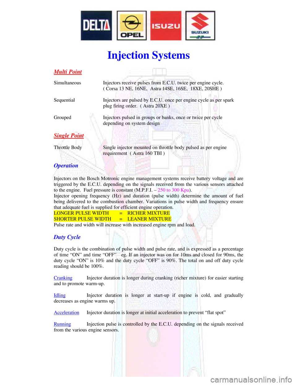
Multi PointSimultaneousInjectors receive pulses from E.C.U. twice per engine cycle.
( Corsa 13 NE, 16NE, Astra 14SE, 16SE, 18XE, 20SHE )
SequentialInjectors are pulsed by E.C.U. once per engine cycle as per spark
plug firing order. ( Astra 20XE )
GroupedInjectors pulsed in groups or banks, once or twice per cycle
depending on system design
Single PointThrottle BodySingle injector mounted on throttle body pulsed as per engine
requirement ( Astra 160 TBI )
Operation
Injectors on the Bosch Motronic engine management systems receive battery voltage and are
triggered by the E.C.U. depending on the signals received from the various sensors attached
to the engine. Fuel pressure is constant (M.P.F.I. – 250 to 300 Kpa).
Injector opening frequency (Hz) and duration (pulse width) determine the amount of fuel
being delivered to the combustion chamber. Variations in pulse width and frequency ensure
that adequate fuel is supplied for efficient engine operation.LONGER PULSE WIDTH= RICHER MIXTURESHORTER PULSE WIDTH= LEANER MIXTURE
Pulse rate and width will increase with increased engine rpm and load.
Duty Cycle
Duty cycle is the combination of pulse width and pulse rate, and is expressed as a percentage
of time “ON” and time “OFF” eg. If an injector was on for 10ms and closed for 90ms, the
duty cycle “ON” is 10% and the duty cycle “OFF” is 90%. The total on and off duty cycle
reading should be 100%.
CrankingInjector duration is longer during cranking (richer mixture) for easier startingand to promote warm-up.
IdlingInjector duration is longer at start-up if engine is cold, and graduallydecreases as engine warms up.
AccelerationInjector duration is longer at initial acceleration to prevent “flat spot”RunningInjection pulse is controlled by the E.C.U. depending on the signals receivedfrom the various engine sensors.
Page 1035 of 1070

Downloaded from www.Manualslib.com manuals search engine 7.9.9 Coasting conditions
7.9.10 Flooded engine conditions
7.9.11 Full load operation
8.0 IDLE SPEED
9.0 IMMOBILISER OPERATION
10.0 DEFAULT MODE SELECTION
11.0 DIAGNOSTICS
11.1 Diagnostic codes
11.2 Volt- and ohmmeter
11.2.1 Battery voltage
11.2.2 Ignition voltage
11.2.3 TPS supply voltage
11.2.4 TPS input signal voltage
11.2.5 CO potentiometer supply voltage
11.2.6 MAP sensor supply voltage
11.2.7 MAP sensor signal voltage
11.2.8 Timing map selector
11.2.9 Fuel mixture selector
11.2.10 EWT sensor
11.2.11 MAT sensor
11.3 Fault finding
11.4 D-TEQ200 PC based tester
11.4.1 Description
11.4.2 Installation
11.4.3 Operation
11.5 C-TEQ200 component tester
11.5.1 Description
11.5.2 Operation
Page 1036 of 1070

Downloaded from www.Manualslib.com manuals search engine 1 PRODUCT DESCRIPTION
The DEFITA200 range of ECU's (Engine Control Units) is
microcontroller based and controls the spark timing, fuel
injection and certain other functions of internal combustion
engines electronically, thus ensuring optimum operating
efficiency.
DEFITA200 is an abbreviation for Dupec Electronic Fuel
Injection and Timing Advance.
2 FEATURES
The DEFITA200 range of ECU's is designed, developed and
manufactured in the Republic of South Africa and offers the
following features:
Standard functions:
- Spark timing up to 7,810 r.p.m. on 4 cylinder engines
- Spark timing based on engine load, temperature
crankshaft position/speed and battery voltage
- Automatic altitude compensation by measurement of
manifold absolute pressure
- Fuel injection based on engine load, speed, tempera-
ture and manifold air temperature
- Coasting fuel cut-off
- Pre-programmed rev. limiting by fuel cut-off
- Active idle speed control
Page 1041 of 1070

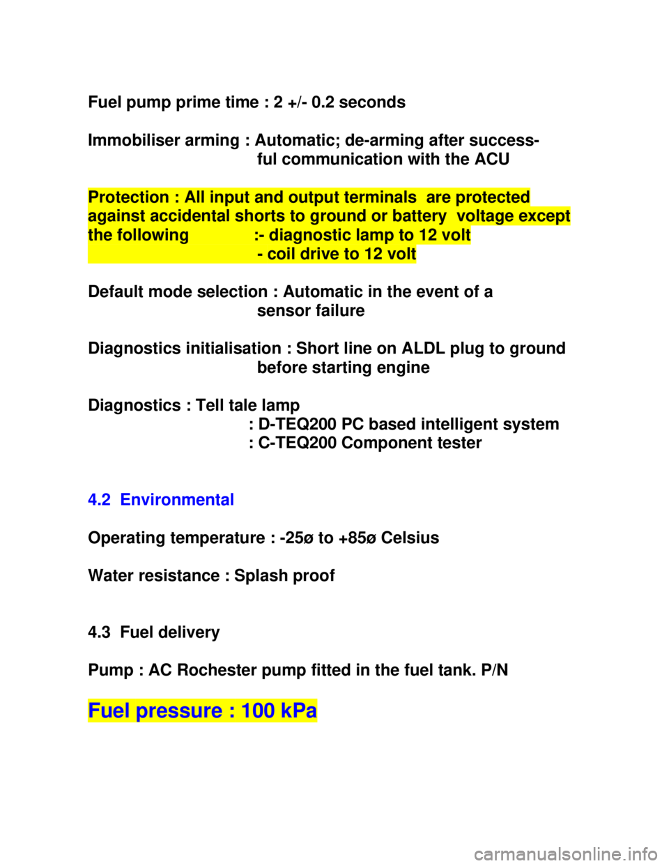
Downloaded from www.Manualslib.com manuals search engine Fuel pump prime time : 2 +/- 0.2 seconds
Immobiliser arming : Automatic; de-arming after success-
ful communication with the ACUProtection : All input and output terminals are protectedagainst accidental shorts to ground or battery voltage exceptthe following :- diagnostic lamp to 12 volt - coil drive to 12 volt
Default mode selection : Automatic in the event of a
sensor failure
Diagnostics initialisation : Short line on ALDL plug to ground
before starting engine
Diagnostics : Tell tale lamp
: D-TEQ200 PC based intelligent system
: C-TEQ200 Component tester
4.2 Environmental
Operating temperature : -25ø to +85ø Celsius
Water resistance : Splash proof
4.3 Fuel delivery
Pump : AC Rochester pump fitted in the fuel tank. P/NFuel pressure : 100 kPa
Page 1043 of 1070

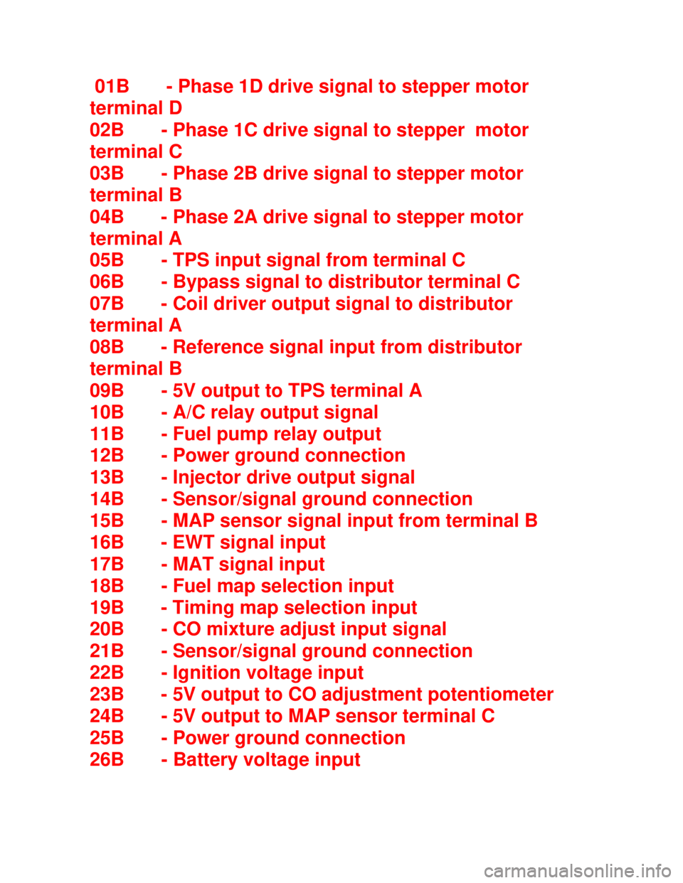
Downloaded from www.Manualslib.com manuals search engine 01B - Phase 1D drive signal to stepper motor
terminal D
02B - Phase 1C drive signal to stepper motor
terminal C
03B - Phase 2B drive signal to stepper motor
terminal B
04B - Phase 2A drive signal to stepper motor
terminal A
05B - TPS input signal from terminal C
06B - Bypass signal to distributor terminal C
07B - Coil driver output signal to distributor
terminal A
08B - Reference signal input from distributor
terminal B
09B - 5V output to TPS terminal A
10B - A/C relay output signal
11B - Fuel pump relay output
12B - Power ground connection
13B - Injector drive output signal
14B - Sensor/signal ground connection
15B - MAP sensor signal input from terminal B
16B - EWT signal input
17B - MAT signal input
18B - Fuel map selection input
19B - Timing map selection input
20B - CO mixture adjust input signal
21B - Sensor/signal ground connection
22B - Ignition voltage input
23B - 5V output to CO adjustment potentiometer
24B - 5V output to MAP sensor terminal C
25B - Power ground connection
26B - Battery voltage input
Page 1044 of 1070

Downloaded from www.Manualslib.com manuals search engine 6 SPARK TIMING
Spark timing and fuel injection for DEFITA200 ECU's is
calculated by a central processing unit and are based on:
I - MAP
II - EWT
III - Battery voltage
IV - Crankshaft position
V - Engine speed
VI - Throttle position
The optimum timing advance curves for a given engine are
determined by running the engine on an engine dynamometer
under any combination of the above-mentioned conditions.
This process is known as mapping the engine. The mapping is
further refined by extensive driving tests.
The mapped data regarding the engine is stored in a ROM
(Read Only Memory) within the ECU.
The following processes take place when calculating the
advance angle:
I - engine speed and crankshaft position measurement
II - engine load measurement
III - advance angle look-up
IV - ignition firing delay calculation
Page 1048 of 1070

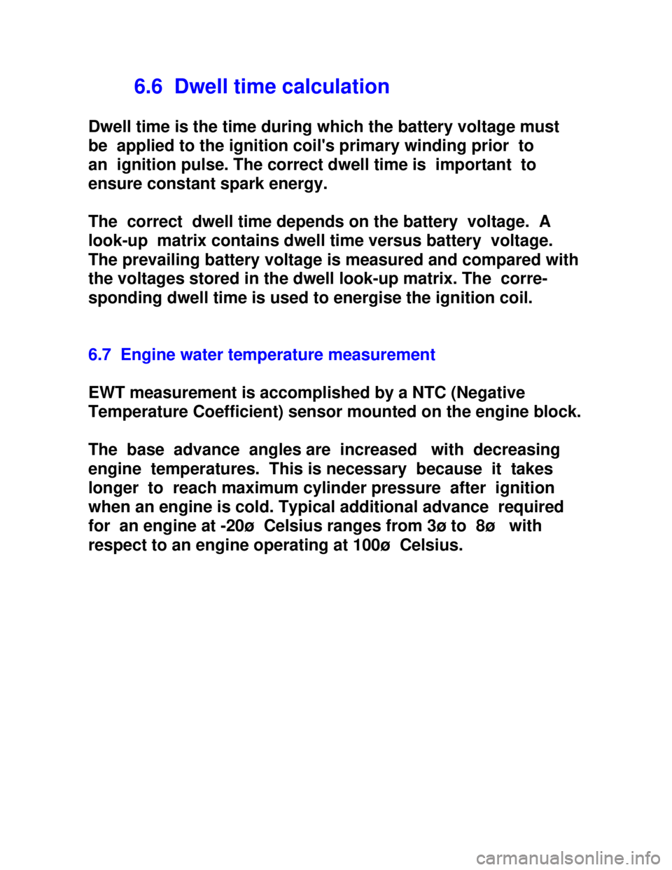
Downloaded from www.Manualslib.com manuals search engine 6.6 Dwell time calculation
Dwell time is the time during which the battery voltage must
be applied to the ignition coil's primary winding prior to
an ignition pulse. The correct dwell time is important to
ensure constant spark energy.
The correct dwell time depends on the battery voltage. A
look-up matrix contains dwell time versus battery voltage.
The prevailing battery voltage is measured and compared with
the voltages stored in the dwell look-up matrix. The corre-
sponding dwell time is used to energise the ignition coil.
6.7 Engine water temperature measurement
EWT measurement is accomplished by a NTC (Negative
Temperature Coefficient) sensor mounted on the engine block.
The base advance angles are increased with decreasing
engine temperatures. This is necessary because it takes
longer to reach maximum cylinder pressure after ignition
when an engine is cold. Typical additional advance required
for an engine at -20ø Celsius ranges from 3ø to 8ø with
respect to an engine operating at 100ø Celsius.
Page 1053 of 1070

Downloaded from www.Manualslib.com manuals search engine Volumetric efficiency depends mainly on the:
a) Inlet valve and camshaft design
b) Inlet manifold design
c) Engine speed
The volumetric efficiency is normally less than one (1) and
has the effect that the actual air mass entering the cylin-
der will be less than the measured value.
Peak volumetric efficiency co-insides with the engine speed
where the maximum torque is developed.
7.4 FUEL METERING
Now that a method has been established to determine the air
mass entering the engine it is possible to calculate the
quantity of fuel to be injected to achieve the required A/F
ratio. An electric fuel pump delivers fuel at a constant
pressure to the injector which is opened for the required
injection duration. The fuel pressure is regulated by a
mechanical pressure regulator.
The fuel mass to be injected is:
Fm = Am/(A/F) Where Fm = Fuel mass
Am = Air mass
Since the fuel is injected in bursts it is necessary to know
the fuel flow rate of the injector, pump and regulator
system, as well as the injector opening and closing delays
at various battery voltages to enable calculation of the
injection duration.