Page 1054 of 1070

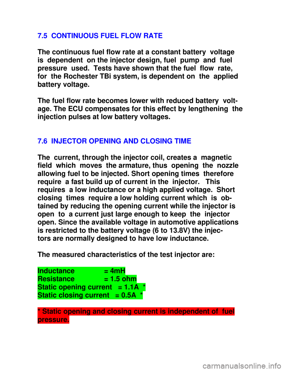
Downloaded from www.Manualslib.com manuals search engine 7.5 CONTINUOUS FUEL FLOW RATE
The continuous fuel flow rate at a constant battery voltage
is dependent on the injector design, fuel pump and fuel
pressure used. Tests have shown that the fuel flow rate,
for the Rochester TBi system, is dependent on the applied
battery voltage.
The fuel flow rate becomes lower with reduced battery volt-
age. The ECU compensates for this effect by lengthening the
injection pulses at low battery voltages.
7.6 INJECTOR OPENING AND CLOSING TIME
The current, through the injector coil, creates a magnetic
field which moves the armature, thus opening the nozzle
allowing fuel to be injected. Short opening times therefore
require a fast build up of current in the injector. This
requires a low inductance or a high applied voltage. Short
closing times require a low holding current which is ob-
tained by reducing the opening current while the injector is
open to a current just large enough to keep the injector
open. Since the available voltage in automotive applications
is restricted to the battery voltage (6 to 13.8V) the injec-
tors are normally designed to have low inductance.
The measured characteristics of the test injector are:Inductance = 4mHResistance = 1.5 ohmStatic opening current = 1.1A *Static closing current = 0.5A ** Static opening and closing current is independent of fuelpressure.
Page 1055 of 1070
Downloaded from www.Manualslib.com manuals search engine The injector drive circuit allows a pull-in current of 4A
and a holding current of 1A. Once an injector current of 4A
is reached the circuit will automatically reduce it to 1A.
Injector opening and closing times vary with battery voltage
and vary between 0.2 ms at 14 volt and 1.35 ms at 6.5 volt.
The ECU takes this into account by measuring the battery
voltage before calculating the injection times.
The electrical opening duration of the injector consists of
the sum of the opening and closing delays and the true
required injection duration.
7.7 INJECTION TIMING
Under static conditions (constant engine load and speed)
fuel will be injected in synchronisation with the crankshaft
position and speed reference signal, i.e. once per intake
stroke. Fuel injection will commence 0.5 ms after the 10ø
BTDC reference.
Page 1056 of 1070

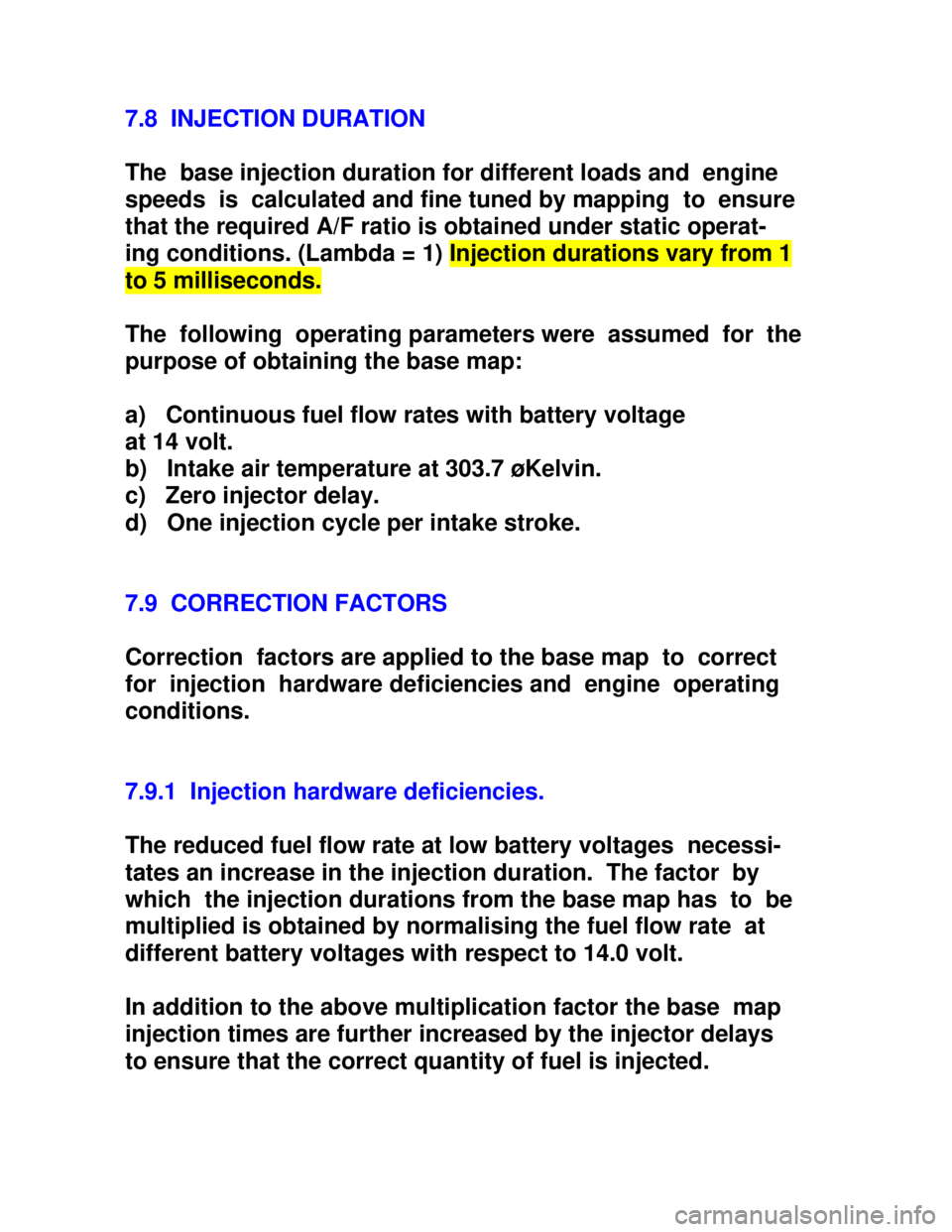
Downloaded from www.Manualslib.com manuals search engine 7.8 INJECTION DURATION
The base injection duration for different loads and engine
speeds is calculated and fine tuned by mapping to ensure
that the required A/F ratio is obtained under static operat-
ing conditions. (Lambda = 1) Injection durations vary from 1to 5 milliseconds.
The following operating parameters were assumed for the
purpose of obtaining the base map:
a) Continuous fuel flow rates with battery voltage
at 14 volt.
b) Intake air temperature at 303.7 øKelvin.
c) Zero injector delay.
d) One injection cycle per intake stroke.
7.9 CORRECTION FACTORS
Correction factors are applied to the base map to correct
for injection hardware deficiencies and engine operating
conditions.
7.9.1 Injection hardware deficiencies.
The reduced fuel flow rate at low battery voltages necessi-
tates an increase in the injection duration. The factor by
which the injection durations from the base map has to be
multiplied is obtained by normalising the fuel flow rate at
different battery voltages with respect to 14.0 volt.
In addition to the above multiplication factor the base map
injection times are further increased by the injector delays
to ensure that the correct quantity of fuel is injected.
Page 1061 of 1070

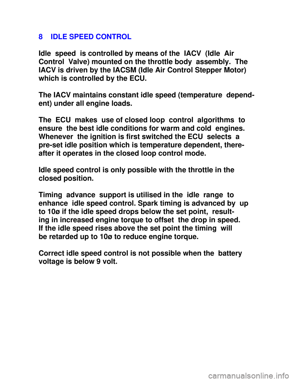
Downloaded from www.Manualslib.com manuals search engine 8 IDLE SPEED CONTROL
Idle speed is controlled by means of the IACV (Idle Air
Control Valve) mounted on the throttle body assembly. The
IACV is driven by the IACSM (Idle Air Control Stepper Motor)
which is controlled by the ECU.
The IACV maintains constant idle speed (temperature depend-
ent) under all engine loads.
The ECU makes use of closed loop control algorithms to
ensure the best idle conditions for warm and cold engines.
Whenever the ignition is first switched the ECU selects a
pre-set idle position which is temperature dependent, there-
after it operates in the closed loop control mode.
Idle speed control is only possible with the throttle in the
closed position.
Timing advance support is utilised in the idle range to
enhance idle speed control. Spark timing is advanced by up
to 10ø if the idle speed drops below the set point, result-
ing in increased engine torque to offset the drop in speed.
If the idle speed rises above the set point the timing will
be retarded up to 10ø to reduce engine torque.
Correct idle speed control is not possible when the battery
voltage is below 9 volt.
Page 1065 of 1070
Downloaded from www.Manualslib.com manuals search engine DIAGNOSTIC CODES
Code Cause
_____________________________________________________
14 Coolant temperature sensor voltage too low
15 Coolant temperature sensor voltage too high
21 TPS voltage too high
22 TPS voltage too low
25 MAT sensor voltage too low
26 MAT sensor voltage too high
33 MAP sensor voltage too high
34 MAP sensor voltage too low
35 Idle control stepper motor failure
36 Timing map selector error
42 Reference signal error/Engine stall
(Diagnostic lamp will not turn ON)
44 Fuel map selector error
48 Battery voltage too low
49 Battery voltage too high
65 CO potentiometer voltage out of range
Page 1066 of 1070
Downloaded from www.Manualslib.com manuals search engine 11.2 Volt- and ohmmeter
No repair work inside the ECU's is possible and
recommended.
A multimeter could however be used to ensure that the fol-
lowing inputs to the ECU are present:
11.2.1 Battery voltage:
11.2.2 The voltage measured between terminals
26B (pos) and 25B (neg) should be equal to the battery
voltage (6 and 16 VDC).
11.2.2 Ignition voltage: The voltage between terminal 22B
and
power ground should be equal to the battery voltage with
the ignition turned on.
11.2.3 TPS supply voltage: The voltage between terminal
09B
and signal ground should be between 4.6 and 5.2 volt.
11.2.4 TPS input signal voltage: The voltage between terminal
05B and signal ground should be:
Closed throttle 0.3 < VTPS < 1.0
Part load 1.0 < VTPS < 3.11
WOT 3.11 < VTPS < 5.2