Page 1034 of 1070

Downloaded from www.Manualslib.com manuals search engine CONTENTS
1.0 PRODUCT DESCRIPTION
2.0 FEATURES
3.0 PRODUCT IDENTIFICATION AND APPLICATION
4.0 SPECIFICATION
4.1 Electrical
4.2 Environmental
4.3 Fuel delivery
5.0 CONNECTIONS
6.0 SPARK TIMING
6.1 Distributor bypass operation
6.2 Engine speed and crankshaft
position measurement
6.3 Engine load measurement
6.4 Advance angle look-up
6.5 Ignition firing delay calculation
6.6 Dwell time calculation
6.7 Engine water temperature measurement
7.0 FUEL INJECTION
7.1 Air mass to fuel mass ratio
7.2 Air mass measurement
7.3 Speed density concept
7.4 Fuel metering
7.5 Continuous fuel flow rate
7.6 Injector opening and closing times
7.7 Injection timing
7.8 Injection duration
7.9 Correction factors
7.9.1 Injection hardware deficiencies
7.9.2 Engine operating conditions
7.9.3 Intake air temperature
7.9.4 Engine temperature
7.9.5 Cold starting conditions
7.9.6 Post-start and warm-up conditions
7.9.7 Acceleration conditions
7.9.8 Deceleration lean-out conditions
Page 1039 of 1070
Downloaded from www.Manualslib.com manuals search engine 4 SPECIFICATION
The following specification is applicable to DEFITA200 P/N:
A020-C ECU's unless otherwise stated:
4.1 Electrical
Operating voltage : 9 to 15 VDC continuous : 6 to 16 VDC limited functions : 24 VDC for 60 seconds maximum
Operating current : Less than 500 mA
Standby current : Less than 12 mA (>1 minute after
ignition off)
Timing accuracy : +/- 0.5 degrees
R.p.m. limit : 6,297
Reference signal : Negative edge from Distributor Y24
at 10ø BTDC
Base timing : 10ø BTDC r.p.m. < 450 or diagnostics initia- lised after starting
Mapped timing : r.p.m. > 450 and diagnostics dis-
abled
Selectable octane maps : 97 RON Factory fitted
: 93 RON
: 87 RON
: 87D RON (For fuel with octane
below 87 RON)
Selectable by interchanging octane plug on harness
Page 1043 of 1070

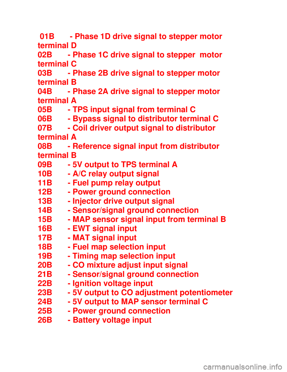
Downloaded from www.Manualslib.com manuals search engine 01B - Phase 1D drive signal to stepper motor
terminal D
02B - Phase 1C drive signal to stepper motor
terminal C
03B - Phase 2B drive signal to stepper motor
terminal B
04B - Phase 2A drive signal to stepper motor
terminal A
05B - TPS input signal from terminal C
06B - Bypass signal to distributor terminal C
07B - Coil driver output signal to distributor
terminal A
08B - Reference signal input from distributor
terminal B
09B - 5V output to TPS terminal A
10B - A/C relay output signal
11B - Fuel pump relay output
12B - Power ground connection
13B - Injector drive output signal
14B - Sensor/signal ground connection
15B - MAP sensor signal input from terminal B
16B - EWT signal input
17B - MAT signal input
18B - Fuel map selection input
19B - Timing map selection input
20B - CO mixture adjust input signal
21B - Sensor/signal ground connection
22B - Ignition voltage input
23B - 5V output to CO adjustment potentiometer
24B - 5V output to MAP sensor terminal C
25B - Power ground connection
26B - Battery voltage input
Page 1045 of 1070

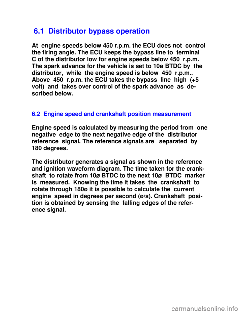
Downloaded from www.Manualslib.com manuals search engine 6.1 Distributor bypass operation
At engine speeds below 450 r.p.m. the ECU does not control
the firing angle. The ECU keeps the bypass line to terminal
C of the distributor low for engine speeds below 450 r.p.m.
The spark advance for the vehicle is set to 10ø BTDC by the
distributor, while the engine speed is below 450 r.p.m..
Above 450 r.p.m. the ECU takes the bypass line high (+5
volt) and takes over control of the spark advance as de-
scribed below.
6.2 Engine speed and crankshaft position measurement
Engine speed is calculated by measuring the period from one
negative edge to the next negative edge of the distributor
reference signal. The reference signals are separated by
180 degrees.
The distributor generates a signal as shown in the reference
and ignition waveform diagram. The time taken for the crank-
shaft to rotate from 10ø BTDC to the next 10ø BTDC marker
is measured. Knowing the time it takes the crankshaft to
rotate through 180ø it is possible to calculate the current
engine speed in degrees per second (ø/s). Crankshaft posi-
tion is obtained by sensing the falling edges of the refer-
ence signal.
Page 1047 of 1070
Downloaded from www.Manualslib.com manuals search engine 6.5 Ignition firing delay calculation
The advance angle obtained from the look-up matrix is sub-
tracted from the 10ø BTDC marker on the distributor shaft to
obtain the firing angle delay.
Example: Advance angle = -20ø on next cycle
Marker position = -10ø
Firing angle delay = 180ø-(-10ø)-20ø
= 170ødelay
Having determined the engine speed previously in degrees per
second it is now possible to calculate the delay time after
the BTDC marker that corresponds with the required advance
angle.
Example: Crankshaft speed = 5,400 r.p.m.
Distributor speed = 2,700 r.p.m.
= 2,700 / 60 r.p.s.
= 45 r.p.s.
= 45x360 ø/s
Crankshaft speed = 2x45x360 ø/s
= 30,400 ø/s
170ø rotation delay = 170 / 30,400 s
= 5.59 milli-second delay
Page 1063 of 1070
Downloaded from www.Manualslib.com manuals search engine 10 DEFAULT MODE SELECTION
When the ECU detects a faulty signal from one of its sensors
it will substitute a default signal value to enable the
vehicle to be driven with degraded performance (see para-
graph 10.1).
Faulty sensor Substitute value/sensor
_____________________________________________________
______
EWT Warm engine - 100 øC
MAT 31 øC
Fuel map selector Zero percent enrichment
Timing map selector Map T1 - RON 87D
TPS Idle speed - 1,000 to
2,000 r.p.m.
MAP TPS and idle speed -
1,000 to 2,000 r.p.m.
Disable distributor
bypass operation and
fix spark timing at
10ø BTDC
CO potentiometer Zero percent