Page 1028 of 1070

Downloaded from www.Manualslib.com manuals search engine CO2 and O2 Analysis
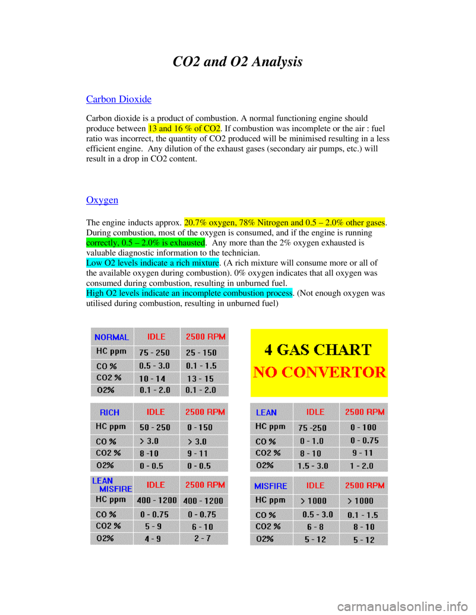
Carbon DioxideCarbon dioxide is a product of combustion. A normal functioning engine should
produce between 13 and 16 % of CO2. If combustion was incomplete or the air : fuel
ratio was incorrect, the quantity of CO2 produced will be minimised resulting in a less
efficient engine. Any dilution of the exhaust gases (secondary air pumps, etc.) will
result in a drop in CO2 content.
OxygenThe engine inducts approx. 20.7% oxygen, 78% Nitrogen and 0.5 – 2.0% other gases.
During combustion, most of the oxygen is consumed, and if the engine is runningcorrectly, 0.5 – 2.0% is exhausted. Any more than the 2% oxygen exhausted is
valuable diagnostic information to the technician.Low O2 levels indicate a rich mixture. (A rich mixture will consume more or all of
the available oxygen during combustion). 0% oxygen indicates that all oxygen was
consumed during combustion, resulting in unburned fuel.High O2 levels indicate an incomplete combustion process. (Not enough oxygen was
utilised during combustion, resulting in unburned fuel)
Page 1041 of 1070
Downloaded from www.Manualslib.com manuals search engine Fuel pump prime time : 2 +/- 0.2 seconds
Immobiliser arming : Automatic; de-arming after success-
ful communication with the ACUProtection : All input and output terminals are protectedagainst accidental shorts to ground or battery voltage exceptthe following :- diagnostic lamp to 12 volt - coil drive to 12 volt
Default mode selection : Automatic in the event of a
sensor failure
Diagnostics initialisation : Short line on ALDL plug to ground
before starting engine
Diagnostics : Tell tale lamp
: D-TEQ200 PC based intelligent system
: C-TEQ200 Component tester
4.2 Environmental
Operating temperature : -25ø to +85ø Celsius
Water resistance : Splash proof
4.3 Fuel delivery
Pump : AC Rochester pump fitted in the fuel tank. P/NFuel pressure : 100 kPa
Page 1043 of 1070

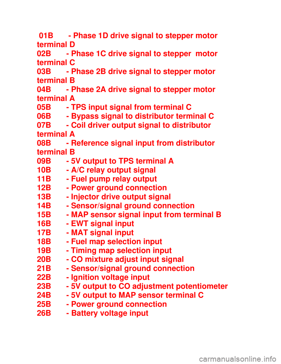
Downloaded from www.Manualslib.com manuals search engine 01B - Phase 1D drive signal to stepper motor
terminal D
02B - Phase 1C drive signal to stepper motor
terminal C
03B - Phase 2B drive signal to stepper motor
terminal B
04B - Phase 2A drive signal to stepper motor
terminal A
05B - TPS input signal from terminal C
06B - Bypass signal to distributor terminal C
07B - Coil driver output signal to distributor
terminal A
08B - Reference signal input from distributor
terminal B
09B - 5V output to TPS terminal A
10B - A/C relay output signal
11B - Fuel pump relay output
12B - Power ground connection
13B - Injector drive output signal
14B - Sensor/signal ground connection
15B - MAP sensor signal input from terminal B
16B - EWT signal input
17B - MAT signal input
18B - Fuel map selection input
19B - Timing map selection input
20B - CO mixture adjust input signal
21B - Sensor/signal ground connection
22B - Ignition voltage input
23B - 5V output to CO adjustment potentiometer
24B - 5V output to MAP sensor terminal C
25B - Power ground connection
26B - Battery voltage input
Page 1052 of 1070

Downloaded from www.Manualslib.com manuals search engine 7.3 SPEED DENSITY CONCEPT
If we know the density of the air inside a container it is
possible to calculate the exact mass of the air inside the
container.
Am = Va*p Where Am = Air mass (g)
Va = Air volume (cc)
p = Air density (g/cc)
In an automotive FI application the quantity of fuel to be
injected can be calculated if the displacement volume of the
cylinder and the density of air within the cylinder at the
onset of the compression stroke are known.
The air density could be determined by measuring the abso-
lute pressure and absolute temperature of the air. In an
automotive application it is, however, not practical to
directly measure the air pressure and temperature inside the
cylinder. To overcome this limitation the air pressure and
temperature are measured in the inlet manifold. This leads
to certain pressure measurement errors for which corrections
have to be made.
To understand and correct these errors the engine is mo-
delled as an air pump. For the purpose of explaining these
problems one has to view the engine as a pump sucking air
from the inlet manifold through a restriction which is
formed by the inlet valve in the open position. The dynamic
properties of the air moving past the inlet valves are
engine speed dependent and to such an extent that the inlet
manifold pressure will tend to be slightly higher than the
in-cylinder pressure at the end of an inlet stroke. This
leads to higher than actual air mass measurements which
have
to be corrected. The air pumping efficiency is called the
volumetric efficiency of the engine.
Page 1053 of 1070

Downloaded from www.Manualslib.com manuals search engine Volumetric efficiency depends mainly on the:
a) Inlet valve and camshaft design
b) Inlet manifold design
c) Engine speed
The volumetric efficiency is normally less than one (1) and
has the effect that the actual air mass entering the cylin-
der will be less than the measured value.
Peak volumetric efficiency co-insides with the engine speed
where the maximum torque is developed.
7.4 FUEL METERING
Now that a method has been established to determine the air
mass entering the engine it is possible to calculate the
quantity of fuel to be injected to achieve the required A/F
ratio. An electric fuel pump delivers fuel at a constant
pressure to the injector which is opened for the required
injection duration. The fuel pressure is regulated by a
mechanical pressure regulator.
The fuel mass to be injected is:
Fm = Am/(A/F) Where Fm = Fuel mass
Am = Air mass
Since the fuel is injected in bursts it is necessary to know
the fuel flow rate of the injector, pump and regulator
system, as well as the injector opening and closing delays
at various battery voltages to enable calculation of the
injection duration.
Page 1054 of 1070

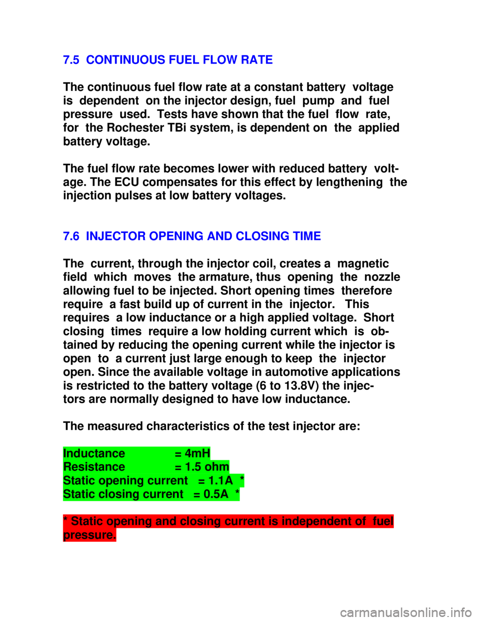
Downloaded from www.Manualslib.com manuals search engine 7.5 CONTINUOUS FUEL FLOW RATE
The continuous fuel flow rate at a constant battery voltage
is dependent on the injector design, fuel pump and fuel
pressure used. Tests have shown that the fuel flow rate,
for the Rochester TBi system, is dependent on the applied
battery voltage.
The fuel flow rate becomes lower with reduced battery volt-
age. The ECU compensates for this effect by lengthening the
injection pulses at low battery voltages.
7.6 INJECTOR OPENING AND CLOSING TIME
The current, through the injector coil, creates a magnetic
field which moves the armature, thus opening the nozzle
allowing fuel to be injected. Short opening times therefore
require a fast build up of current in the injector. This
requires a low inductance or a high applied voltage. Short
closing times require a low holding current which is ob-
tained by reducing the opening current while the injector is
open to a current just large enough to keep the injector
open. Since the available voltage in automotive applications
is restricted to the battery voltage (6 to 13.8V) the injec-
tors are normally designed to have low inductance.
The measured characteristics of the test injector are:Inductance = 4mHResistance = 1.5 ohmStatic opening current = 1.1A *Static closing current = 0.5A ** Static opening and closing current is independent of fuelpressure.