Page 1031 of 1070

Downloaded from www.Manualslib.com manuals search engine Injection Systems
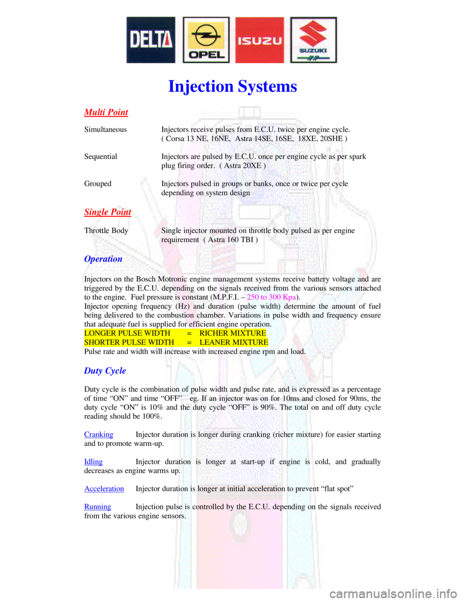
Multi PointSimultaneousInjectors receive pulses from E.C.U. twice per engine cycle.
( Corsa 13 NE, 16NE, Astra 14SE, 16SE, 18XE, 20SHE )
SequentialInjectors are pulsed by E.C.U. once per engine cycle as per spark
plug firing order. ( Astra 20XE )
GroupedInjectors pulsed in groups or banks, once or twice per cycle
depending on system design
Single PointThrottle BodySingle injector mounted on throttle body pulsed as per engine
requirement ( Astra 160 TBI )
Operation
Injectors on the Bosch Motronic engine management systems receive battery voltage and are
triggered by the E.C.U. depending on the signals received from the various sensors attached
to the engine. Fuel pressure is constant (M.P.F.I. – 250 to 300 Kpa).
Injector opening frequency (Hz) and duration (pulse width) determine the amount of fuel
being delivered to the combustion chamber. Variations in pulse width and frequency ensure
that adequate fuel is supplied for efficient engine operation.LONGER PULSE WIDTH= RICHER MIXTURESHORTER PULSE WIDTH= LEANER MIXTURE
Pulse rate and width will increase with increased engine rpm and load.
Duty Cycle
Duty cycle is the combination of pulse width and pulse rate, and is expressed as a percentage
of time “ON” and time “OFF” eg. If an injector was on for 10ms and closed for 90ms, the
duty cycle “ON” is 10% and the duty cycle “OFF” is 90%. The total on and off duty cycle
reading should be 100%.
CrankingInjector duration is longer during cranking (richer mixture) for easier startingand to promote warm-up.
IdlingInjector duration is longer at start-up if engine is cold, and graduallydecreases as engine warms up.
AccelerationInjector duration is longer at initial acceleration to prevent “flat spot”RunningInjection pulse is controlled by the E.C.U. depending on the signals receivedfrom the various engine sensors.
Page 1035 of 1070
Downloaded from www.Manualslib.com manuals search engine 7.9.9 Coasting conditions
7.9.10 Flooded engine conditions
7.9.11 Full load operation
8.0 IDLE SPEED
9.0 IMMOBILISER OPERATION
10.0 DEFAULT MODE SELECTION
11.0 DIAGNOSTICS
11.1 Diagnostic codes
11.2 Volt- and ohmmeter
11.2.1 Battery voltage
11.2.2 Ignition voltage
11.2.3 TPS supply voltage
11.2.4 TPS input signal voltage
11.2.5 CO potentiometer supply voltage
11.2.6 MAP sensor supply voltage
11.2.7 MAP sensor signal voltage
11.2.8 Timing map selector
11.2.9 Fuel mixture selector
11.2.10 EWT sensor
11.2.11 MAT sensor
11.3 Fault finding
11.4 D-TEQ200 PC based tester
11.4.1 Description
11.4.2 Installation
11.4.3 Operation
11.5 C-TEQ200 component tester
11.5.1 Description
11.5.2 Operation
Page 1037 of 1070
Downloaded from www.Manualslib.com manuals search engine - User selectable spark timing curves for different
fuel octane ratings
- User selectable fuel mixture maps for different
octane ratings
- Automatic default mode selection in the event of
sensor failure allows limp-home operation
- Air-conditioner shutdown control
- Self-diagnostics with fault storage
- Intelligent PC based diagnostics with logging
facility.
- Software immobiliser which prevents hot-wiring
- Repairability. THIS IS NOT A THROW-AWAY UNIT. IT CAN BE REPAIRED AT DUPEC FOR A MINIMAL CHARGE
Page 1041 of 1070
Downloaded from www.Manualslib.com manuals search engine Fuel pump prime time : 2 +/- 0.2 seconds
Immobiliser arming : Automatic; de-arming after success-
ful communication with the ACUProtection : All input and output terminals are protectedagainst accidental shorts to ground or battery voltage exceptthe following :- diagnostic lamp to 12 volt - coil drive to 12 volt
Default mode selection : Automatic in the event of a
sensor failure
Diagnostics initialisation : Short line on ALDL plug to ground
before starting engine
Diagnostics : Tell tale lamp
: D-TEQ200 PC based intelligent system
: C-TEQ200 Component tester
4.2 Environmental
Operating temperature : -25ø to +85ø Celsius
Water resistance : Splash proof
4.3 Fuel delivery
Pump : AC Rochester pump fitted in the fuel tank. P/NFuel pressure : 100 kPa
Page 1042 of 1070
Downloaded from www.Manualslib.com manuals search engine 5 CONNECTIONS
All input and output connections are made via a 48-pin AMP
connector.
TERMINAL NO. DESIGNATION
-----------------------------------------------------------------
01A - NC (no connection)
02A - NC
03A - NC
04A - NC
05A - NC
06A - Diagnostics initialise input
07A - A/C switch input signal
08A - A/C clutch input signal (not used)
09A - Rev. counter output signal
10A - Diagnostic lamp output signal
11A - Sensor/signal ground connection
12A - Sensor/signal ground connection
13A - NC
14A - NC
15A - NC
16A - Diagnostic output signal to D-Teq
17A - Sensor/signal ground connection
18A - Diagnostic input signal from D-Teq
19A - Immobiliser output signal
20A - Sensor/signal ground connection
21A - Immobiliser input signal
22A - Sensor/signal ground connection
Page 1043 of 1070

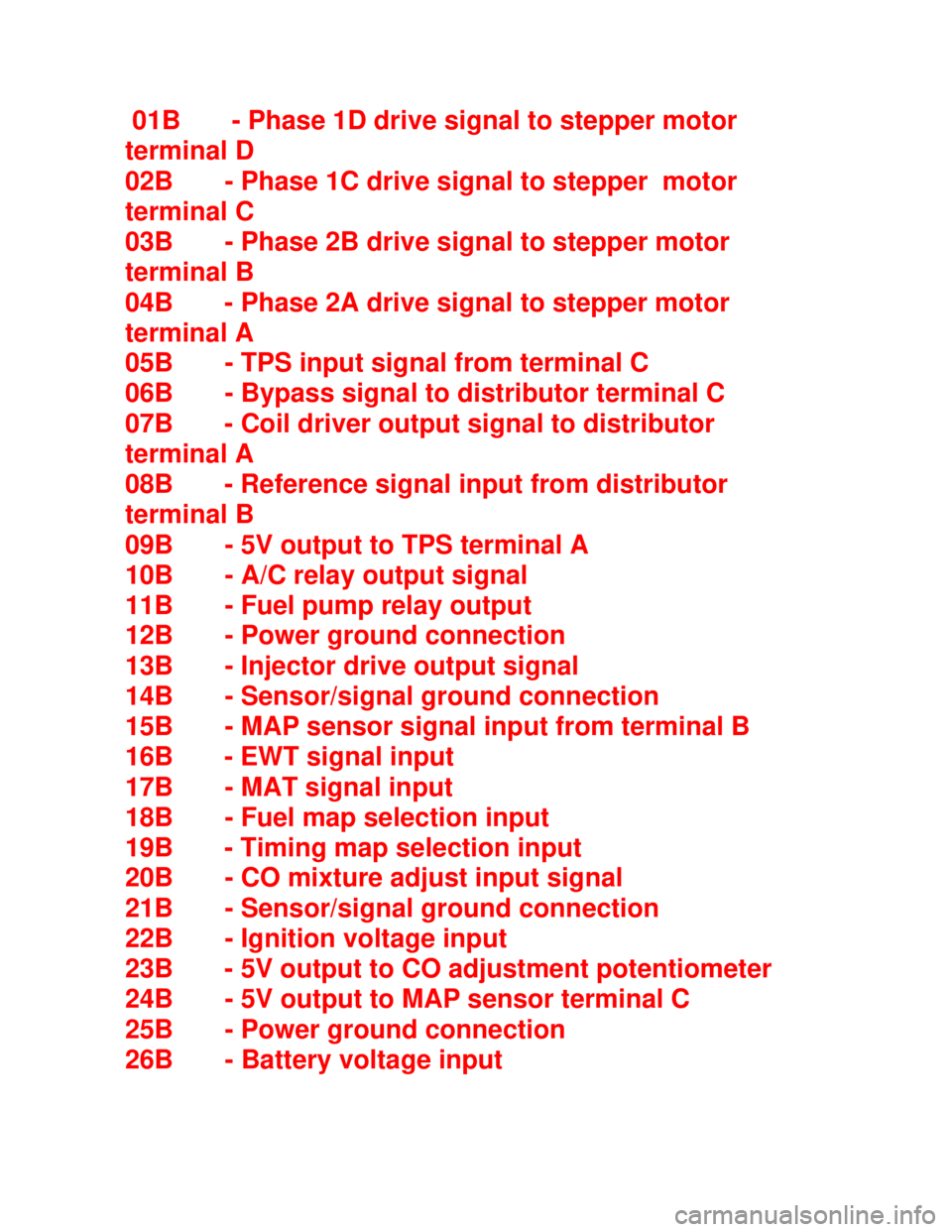
Downloaded from www.Manualslib.com manuals search engine 01B - Phase 1D drive signal to stepper motor
terminal D
02B - Phase 1C drive signal to stepper motor
terminal C
03B - Phase 2B drive signal to stepper motor
terminal B
04B - Phase 2A drive signal to stepper motor
terminal A
05B - TPS input signal from terminal C
06B - Bypass signal to distributor terminal C
07B - Coil driver output signal to distributor
terminal A
08B - Reference signal input from distributor
terminal B
09B - 5V output to TPS terminal A
10B - A/C relay output signal
11B - Fuel pump relay output
12B - Power ground connection
13B - Injector drive output signal
14B - Sensor/signal ground connection
15B - MAP sensor signal input from terminal B
16B - EWT signal input
17B - MAT signal input
18B - Fuel map selection input
19B - Timing map selection input
20B - CO mixture adjust input signal
21B - Sensor/signal ground connection
22B - Ignition voltage input
23B - 5V output to CO adjustment potentiometer
24B - 5V output to MAP sensor terminal C
25B - Power ground connection
26B - Battery voltage input
Page 1046 of 1070
Downloaded from www.Manualslib.com manuals search engine 6.3 Engine load measurement
Engine load is measured by an external MAP ( Manifold Abso-
lute Pressure) sensor. Absolute pressure measurement auto-
matically adjust spark timing for altitude changes. It is also
required to determine the air mass for fuel injection
applications.
6.4 Advance angle look-up
The optimum advance angle obtained by mapping the engine
is stored in a matrix (table) having 10 load and 62 r.p.m.
sites. There are thus 620 possible advance angles stored in
ROM for every RON number used. The CPU (Central
Processing Unit) compares the calculated engine speed and
measured load with the site indexes stored in ROM. If an exact
correspond-ing speed and load site are found it uses the
corresponding advance angle in the matrix. In cases where
exact corre- sponding load and r.p.m. sites are not found the
CPU uses linear interpolation to calculate the corresponding
advance angle to be used.
Page 1048 of 1070

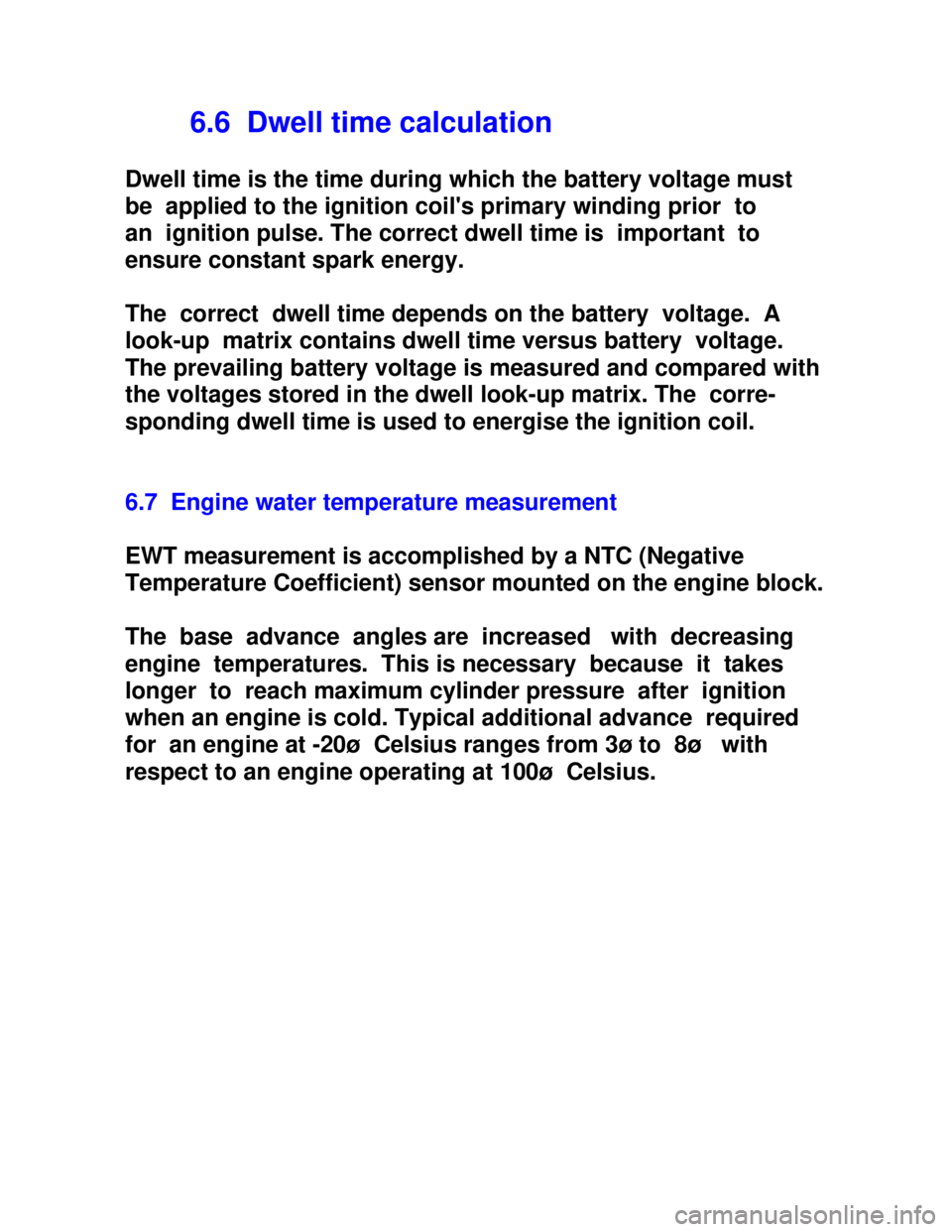
Downloaded from www.Manualslib.com manuals search engine 6.6 Dwell time calculation
Dwell time is the time during which the battery voltage must
be applied to the ignition coil's primary winding prior to
an ignition pulse. The correct dwell time is important to
ensure constant spark energy.
The correct dwell time depends on the battery voltage. A
look-up matrix contains dwell time versus battery voltage.
The prevailing battery voltage is measured and compared with
the voltages stored in the dwell look-up matrix. The corre-
sponding dwell time is used to energise the ignition coil.
6.7 Engine water temperature measurement
EWT measurement is accomplished by a NTC (Negative
Temperature Coefficient) sensor mounted on the engine block.
The base advance angles are increased with decreasing
engine temperatures. This is necessary because it takes
longer to reach maximum cylinder pressure after ignition
when an engine is cold. Typical additional advance required
for an engine at -20ø Celsius ranges from 3ø to 8ø with
respect to an engine operating at 100ø Celsius.