1991 OPEL ASTRA air condition
[x] Cancel search: air conditionPage 1027 of 1070
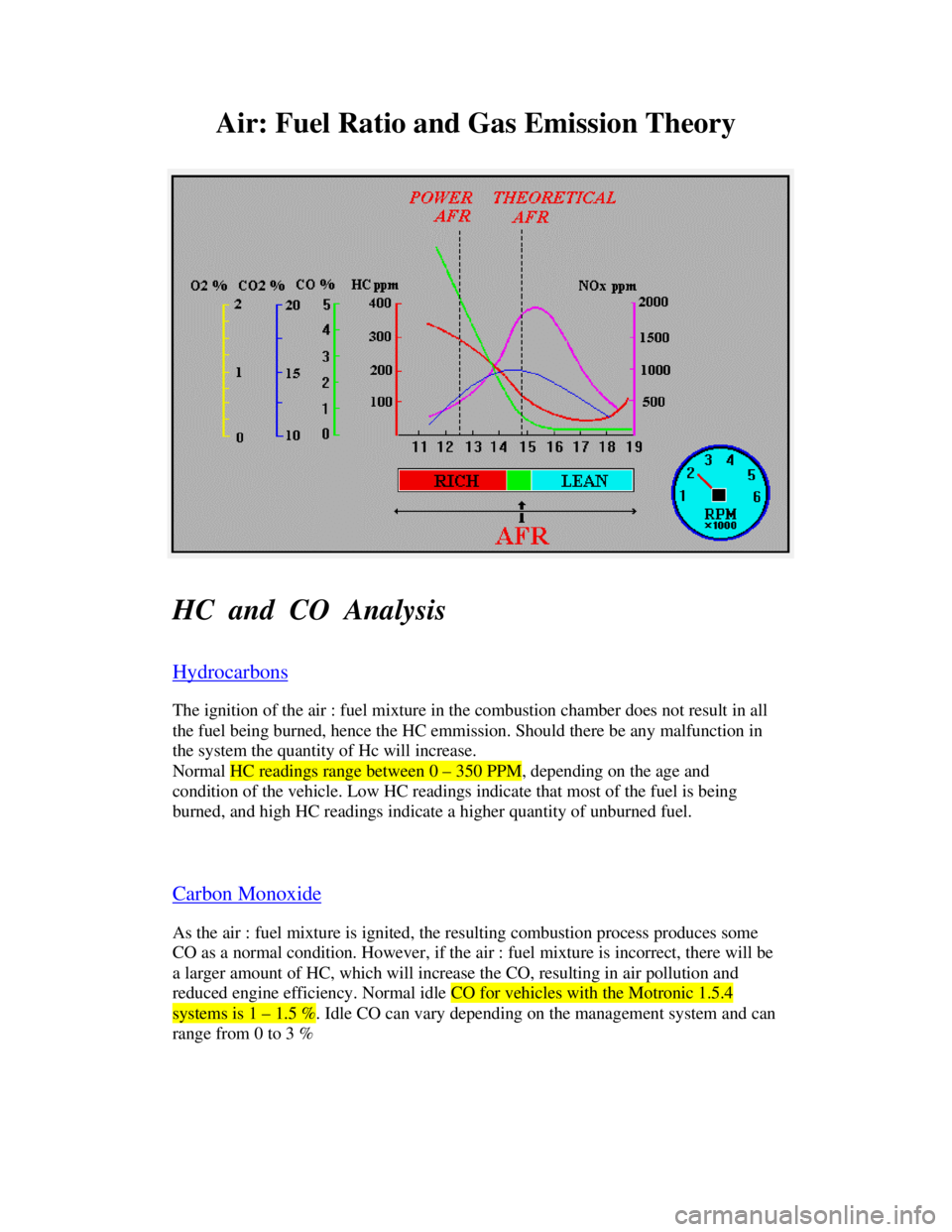
Downloaded from www.Manualslib.com manuals search engine Air: Fuel Ratio and Gas Emission Theory
HC and CO Analysis
HydrocarbonsThe ignition of the air : fuel mixture in the combustion chamber does not result in all
the fuel being burned, hence the HC emmission. Should there be any malfunction in
the system the quantity of Hc will increase.
Normal HC readings range between 0 – 350 PPM, depending on the age and
condition of the vehicle. Low HC readings indicate that most of the fuel is being
burned, and high HC readings indicate a higher quantity of unburned fuel.
Carbon MonoxideAs the air : fuel mixture is ignited, the resulting combustion process produces some
CO as a normal condition. However, if the air : fuel mixture is incorrect, there will be
a larger amount of HC, which will increase the CO, resulting in air pollution and
reduced engine efficiency. Normal idle CO for vehicles with the Motronic 1.5.4systems is 1 – 1.5 %. Idle CO can vary depending on the management system and can
range from 0 to 3 %
Page 1034 of 1070

Downloaded from www.Manualslib.com manuals search engine CONTENTS
1.0 PRODUCT DESCRIPTION
2.0 FEATURES
3.0 PRODUCT IDENTIFICATION AND APPLICATION
4.0 SPECIFICATION
4.1 Electrical
4.2 Environmental
4.3 Fuel delivery
5.0 CONNECTIONS
6.0 SPARK TIMING
6.1 Distributor bypass operation
6.2 Engine speed and crankshaft
position measurement
6.3 Engine load measurement
6.4 Advance angle look-up
6.5 Ignition firing delay calculation
6.6 Dwell time calculation
6.7 Engine water temperature measurement
7.0 FUEL INJECTION
7.1 Air mass to fuel mass ratio
7.2 Air mass measurement
7.3 Speed density concept
7.4 Fuel metering
7.5 Continuous fuel flow rate
7.6 Injector opening and closing times
7.7 Injection timing
7.8 Injection duration
7.9 Correction factors
7.9.1 Injection hardware deficiencies
7.9.2 Engine operating conditions
7.9.3 Intake air temperature
7.9.4 Engine temperature
7.9.5 Cold starting conditions
7.9.6 Post-start and warm-up conditions
7.9.7 Acceleration conditions
7.9.8 Deceleration lean-out conditions
Page 1037 of 1070
Downloaded from www.Manualslib.com manuals search engine - User selectable spark timing curves for different
fuel octane ratings
- User selectable fuel mixture maps for different
octane ratings
- Automatic default mode selection in the event of
sensor failure allows limp-home operation
- Air-conditioner shutdown control
- Self-diagnostics with fault storage
- Intelligent PC based diagnostics with logging
facility.
- Software immobiliser which prevents hot-wiring
- Repairability. THIS IS NOT A THROW-AWAY UNIT. IT CAN BE REPAIRED AT DUPEC FOR A MINIMAL CHARGE
Page 1040 of 1070

Downloaded from www.Manualslib.com manuals search engine Fuel mixture adjustment : - 15% Leaner
: - 10% Leaner
: - 05% Leaner
: + 05% Richer
: + 10% Richer
: + 15% Richer
: + 20% Richer
: + 25% Richer
Selectable by installing optional
mixture selection plug.
Operation only possible in open
throttle position.
Air-conditioner shut-off : Throttle > 88% open OR
: TPS closed and speed < idle r.p.m.
Fuel injection timing : Synchronous with reference signal
Idle CO adjustment : +/- 15% of base fuel map by means
of CO potentiometer with closed
throttle
Coasting cut-out : 1228 r.p.m. - EWT > 78 øC
: 1755 r.p.m. - EWT = 0 øC
Idle speed : 910 r.p.m. - EWT > 78 øC
: 1300 r.p.m. - EWT = 0 øC
: 1050 r.p.m. - A/C ON (EWT > 78 øC)
: 1495 r.p.m. - A/C ON (EWT = 0 øC)
Idle speed control : By means of stepper motor control
of IACV (Idle Air Control Valve)
Wide Open Throttle (WOT) : Throttle > 72% open
Flood compensation : 0.6x base fuel maps in WOT mode
and r.p.m. < 450
Page 1049 of 1070
Downloaded from www.Manualslib.com manuals search engine 7 FUEL INJECTION
It is the function of any fuel injection system to ensure
that the correct mass ratio of air and fuel is delivered to
the engine under all operating conditions. We will concen-
trate on TBi (Throttle Body Injection or alternatively
called single point fuel injection systems) in this docu-
ment.
The availability of powerful low cost microprocessors has
made it possible to fit FI (Fuel Injection) systems to a
larger percentage of vehicles. The ECU (Engine Control Unit)
evaluates input sensor data and calculates the required
output signals to control the engine. The most important
function of a FI system is to measure the air mass entering
the engine and calculate the injector opening duration to
ensure the correct A/F ratio under specific engine operating
conditions. The A/F ratio has a direct effect on the power
output of the engine, fuel consumption and exhaust gas
emissions. It is therefore necessary to exercise precise
control over the opening duration of the injector.
A number of operating conditions exist where the A/F ratio
is deliberately modified and forced to deviate from the
calculated ratio to ensure better drivability and smoother
engine operation. These deviations are classified as A/F
corrections and will later be examined in detail in this
document.
Page 1050 of 1070
Downloaded from www.Manualslib.com manuals search engine 7.1 AIR MASS TO FUEL MASS RATIO
The theoretical air mass to fuel mass ratio required by an
internal-combustion engine for complete combustion is
14.7:1. This ratio is also called the stoichiometric ratio.
The A/F ratio determines the fuel consumption, maximum
engine power output and exhaust gas emission levels. Unfor-
tunately there is no single A/F ratio that optimises these
three requirements.
The ratio of actual air mass supplied to the engine divided
by the theoretical requirement is defined as lambda.
ë = Air mass supplied/theoretical requirement
Where ë = Lambda
ë = 1
The air mass supplied matches the theoretical amount.
ë < 1
A lack of air resulting in a rich mixture. Increased engine
power outputs are obtained for 0.85 < ë < 1.
0.75 < ë < 0.85
A rich mixture suitable for transient conditions where a
sudden load change is experienced.
ë > 1
An excess of air resulting in a lean mixture together with a
reduction in engine power output. Optimum fuel consumption
takes place with 1 < ë < 1.2.
ë > 1.3
Lean mixture making it impossible to achieve reliable igni-
tion.
Page 1056 of 1070
Downloaded from www.Manualslib.com manuals search engine 7.8 INJECTION DURATION
The base injection duration for different loads and engine
speeds is calculated and fine tuned by mapping to ensure
that the required A/F ratio is obtained under static operat-
ing conditions. (Lambda = 1) Injection durations vary from 1to 5 milliseconds.
The following operating parameters were assumed for the
purpose of obtaining the base map:
a) Continuous fuel flow rates with battery voltage
at 14 volt.
b) Intake air temperature at 303.7 øKelvin.
c) Zero injector delay.
d) One injection cycle per intake stroke.
7.9 CORRECTION FACTORS
Correction factors are applied to the base map to correct
for injection hardware deficiencies and engine operating
conditions.
7.9.1 Injection hardware deficiencies.
The reduced fuel flow rate at low battery voltages necessi-
tates an increase in the injection duration. The factor by
which the injection durations from the base map has to be
multiplied is obtained by normalising the fuel flow rate at
different battery voltages with respect to 14.0 volt.
In addition to the above multiplication factor the base map
injection times are further increased by the injector delays
to ensure that the correct quantity of fuel is injected.
Page 1057 of 1070
Downloaded from www.Manualslib.com manuals search engine 7.9.2 Engine operating conditions.
The following engine operating conditions require additional
modifications to the base injection map.
7.9.3 Intake air temperature.
The oxygen content of the intake air is proportional to the
air density and inversely proportional to the air tempera-
ture. It is therefore necessary to correct the base map for
intake air temperature variations. An air intake tempera-
ture correction factor which is normalised with respect to
303.7øK is therefore used.
7.9.4 Engine temperature.
Cold engines exhibit more friction and therefore require
slightly richer A/F ratios to ensure smooth running. Cor-
rections are made for engine temperatures from -13øC to
110øC and normalised with respect to 100øC.
Cold intake manifolds result in considerable wall-wetting
which means that all the injected fuel does not atomise to
form a combustionable mixture. Additional fuel has to be
injected to overcome this effect.