Page 846 of 1333

Circuit Circuit
Application Terminals Terminals
Montero, Pickup 3.0L & Ram-50 3.0L ..... 2 & 4 ............. 1 & 3
���������\
���������\
���������\
���������\
���������\
���������\
���������\
������
POWER STEERING OIL PRESSURE SWITCH
1) Power steering oil pressure switch is mounted on power
steering pump. Disconnect single wire connector at switch. Start
engine.
2) Connect ohmmeter between switch terminal and ground. If
continuity is present with steering wheel in straight-ahead position,
replace switch. If continuity is not present while turning steering
wheel, perform POWER STEERING IDLE-UP SYSTEM TEST. See IDLE-UP SYSTEMS
under IDLE CONTROL SYSTEM.
THROTTLE POSITION SENSOR
1) TPS is mounted to throttle body, at end of throttle shaft.
Disconnect TPS connector. See Fig. 6. Using ohmmeter, measure total
resistance between TPS connector terminals as specified in TPS
CONNECTOR TERMINAL IDENTIFICATION table. If resistance is not 3500-
6500 ohms, replace TPS.
2) Using an analog (needle-type) ohmmeter, measure variable
resistance between TPS connector terminals as specified in TPS
CONNECTOR TERMINAL IDENTIFICATION table.
3) Operate throttle valve from closed to wide open throttle.
If rate of resistance does not change smoothly within 3500-6500 ohms
throughout range of throttle valve movement, replace TPS.
Fig. 6: TPS Sensor Connector Terminal ID
Courtesy of Mitsubishi Motor Sales of America.
TPS CONNECTOR TERMINAL IDENTIFICATION TABLE
���������\
���������\
���������\
���������\
��������
Page 877 of 1333

Fig. 4: 18-Way ECU Connector
Courtesy of Chrysler Motors.
Fig. 5: 24-Way ECU Connector
Courtesy of Chrysler Motors.
Fig. 6: Self-Diagnostic Connector Terminal Identification
Courtesy of Mitsubishi Motor Sales of America.
FAULT CODES
FAULT CODES TABLE���������\
���������\
���������\
���������\
���������\
���������\
�����
Fault Code System Fault Description
11 .................... Open or short in O2 sensor circuit
12 ............... Open or short in airflow sensor circuit
13 ...... Open or short in intake air temp. sensor circuit
14 .......................... Open or short in TPS circuit
15 (1) .... Open or short in motor position sensor circuit
21 ......... Open or short in coolant temp. sensor circuit
22 ........ No voltage change in crank angle sensor signal
23 ............... No voltage change in TDC sensor circuit
24 ( 2) .. No voltage change in vehicle speed sensor signal
25 ........... Open or short in barometric pressure sensor
31 ( 3) ........ Open or short in detonation sensor circuit
41 ..................... Open or short in injector circuit
42 .............. Open or short in fuel pump drive circuit
43 ( 4) ......... Open or short in EGR temp. sensor circuit
Page 1096 of 1333
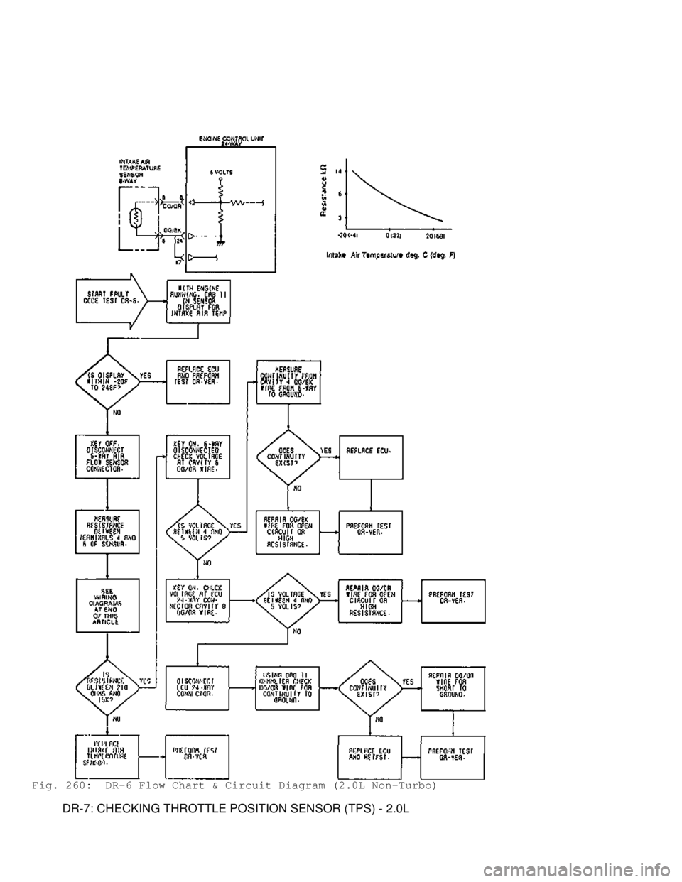
Fig. 260: DR-6 Flow Chart & Circuit Diagram (2.0L Non-Turbo)
DR-7: CHECKING THROTTLE POSITION SENSOR (TPS) - 2.0L
Page 1144 of 1333

Inhibitor Switch (Automatic Transmission Only)
Inhibitor switch senses position of transmission select
lever, indicating engine load due to automatic transmission
engagement. Based on this signal, ECU commands ISC motor to increase
throttle angle, maintaining optimum idle speed.
Intake Air Temperature Sensor
Incorporated in airflow sensor assembly, this resistor-based
sensor measures temperature of incoming air and supplies air density
information to ECU.
Motor Position Sensor (MPS)
Incorporated in ISC motor (or separate unit on some models),
senses ISC motor plunger position and sends electrical signal to ECU.
Oxygen (O2) Sensor
Located in exhaust system, generates an output voltage.
Output voltage varies with oxygen content of exhaust gas stream. ECU
adjusts air/fuel mixture based on signals from oxygen sensor.
Power Steering Oil Pressure Switch
Detects increase in power steering oil pressure. When power
steering oil pressure increases, switch contacts close, signalling
ECU. ECU commands ISC motor, raising idle speed to compensate for drop
in engine RPM due to power steering load.
TDC Sensor
See CRANKSHAFT ANGLE & TDC SENSOR ASSEMBLY.
Throttle Position Sensor (TPS)
A variable resistor mounted on throttle body. ECU uses
voltage signal received from TPS to determine throttle plate angle.
Vehicle Speed Sensor
Located in speedometer in instrument cluster, uses a reed
switch to sense speedometer gear revolutions. ECU uses gear
revolutions to determine vehicle speed.
OUTPUT SIGNALS
NOTE: Vehicles are equipped with different combinations of
computer-controlled components. Not all components listed
below are used on every vehicle. For theory and operation on
each output component, refer to the system indicated in
brackets after component.
CHECK ENGINE Light
See SELF DIAGNOSTIC SYSTEM.
EGR Control Solenoid Valve
See EXHAUST GAS RECIRCULATION (EGR) CONTROL under EMISSION
SYSTEMS.
Fuel Injectors
See FUEL CONTROL under FUEL SYSTEM.
Fuel Pressure Control Solenoid Valve (Turbo Only)
See FUEL DELIVERY under FUEL SYSTEM.
Fuel Pressure Regulator
See FUEL DELIVERY under FUEL SYSTEM.
Fuel Pump Relay (MPI Control Relay)
Page:
< prev 1-8 9-16 17-24