Page 1061 of 1216
BODY - Troubleshootina234 7AUTOMATIC
SEAT BELT N23EBGD
CIRCUIT DIAGRAM
IGNSW1
b
c
ION'H (IGl)
3-BW
I
COMBINATION
METER2
L
:I
3
D-06 i
E
WHEN KE
l%OVEO
14
-----1
I
I
I
I
f51
II
>
I
I:
I
I52
1
I
I13 ;----
1OAb10A\,7“4
4C-52 m
AUTOMATIC
SEAT BELT
CONTROL UNIT
P2
St1ELT
M6-AC-Ul6lZ-NCm
.---
.,*i
i
6
c:
13
W'HEN KEY&TALLEDm
!
43cu
Page 1064 of 1216

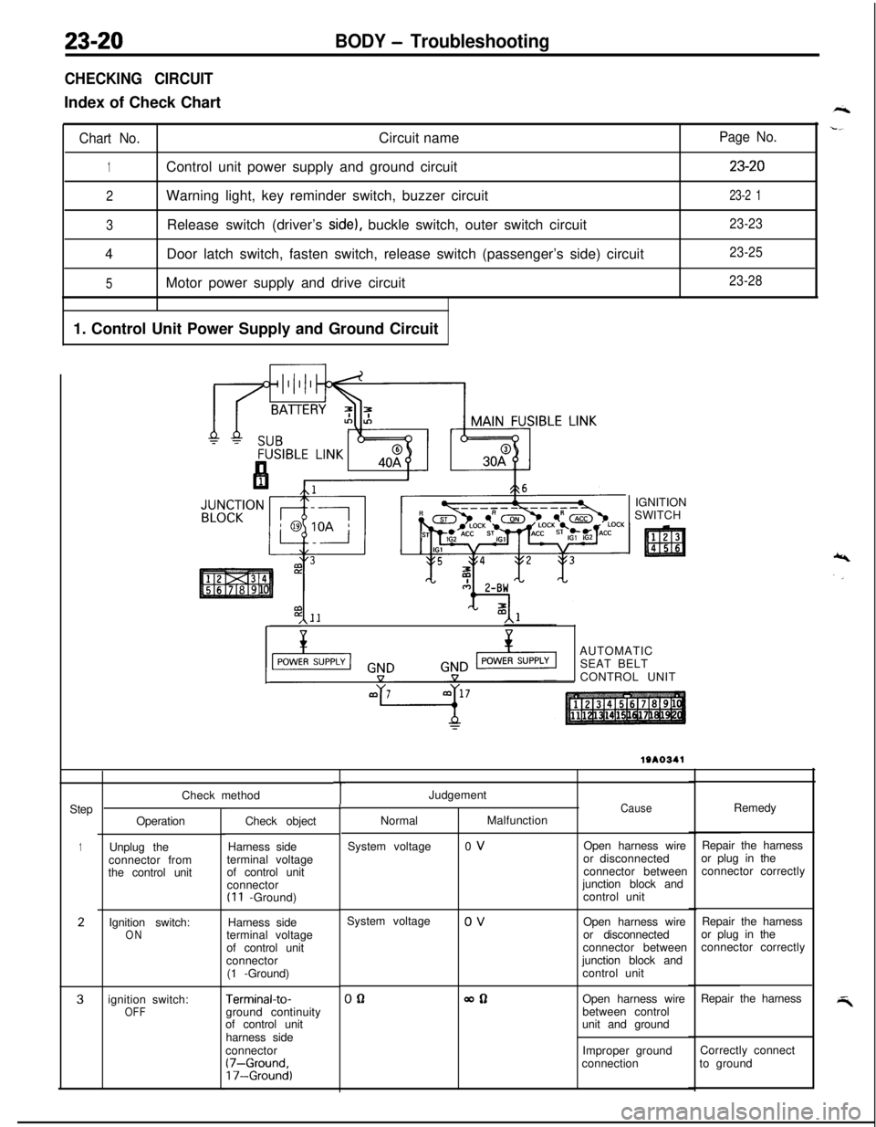
23-20BODY - Troubleshooting
CHECKING CIRCUITIndex of Check Chart
Chart No.Circuit name
1Control unit power supply and ground circuit
2Warning light, key reminder switch, buzzer circuit
3Release switch (driver’s side), buckle switch, outer switch circuit
4Door latch switch, fasten switch, release switch (passenger’s side) circuit
5Motor power supply and drive circuit
1. Control Unit Power Supply and Ground Circuit
Page No.
23-20
23-2 1
23-23
23-25
23-28IGNITION
SWITCH
,\--AUTOMATIC
SEAT BELT
CONTROL UNIT
Step
1
2
3Check method
Operation
Unplug the
connector from
the control unit
Ignition switch:
ONignition switch:
OFFCheck object
Harness side
terminal voltage
of control unit
connector
(I 1 -Ground)
Harness side
terminal voltage
of control unit
connector
(1 -Ground)
Terminal-to-ground continuity
of control unit
harness side
connector
(7-Ground,17-Ground)
TJudgement
NormalMalfunction
System voltage0 VCauseOpen harness wire
or disconnected
connector between
junction block and
control unitRemedy
Repair the harness
or plug in the
connector correctly
System voltage
0 V
Open harness wire
or disconnected
connector between
junction block and
control unitRepair the harness
or plug in the
connector correctly
00allOpen harness wire
between control
unit and groundRepair the harness
Improper groundCorrectly connect
connectionto ground
Page 1065 of 1216
BODY - Troubleshooting23-21
1 2. Warning Light, Key Reminder Switch, Buzzer Circuit 1IIJUNCTION
BLOCK
WARNING LIGHT
gCTy4;NATION
c-7,,7L,,l7,/\
00IOA
IOA
2:y47
.---
141I
I
I
I
I
I
1I
3
2
11
I
I
I13
-I_---
10IGNITION SWITCH
SUB FUSIBLE LINK @AUTOMATIC
SEAT BELT
CONTROL UNIT
t
11 WG
KEY REMINDER
6
\IL!>
Nhen ke
8emoved
13
+ installed
J
2
1SEAT BELT
WARNING BUZZER
20
w
IIem
Page 1066 of 1216

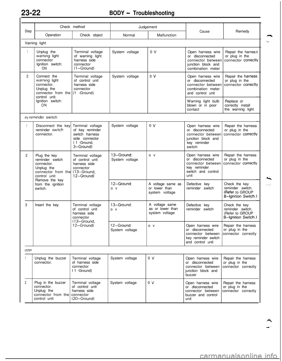
23-22BODY - TroubleshootingCheck method
StepOperation
Check object
Varning lightJudgementCauseRemedy
NormalMalfunction
1Unplug theTerminal voltagewarnrng light
of warning light
connector
harness side
Ignition switch:
connector
ON(I-Ground)
2Connect the
Terminal voltagewarnrng light
of control unit
connector.
harness side
Unplug theconnector
connector from the (1 -Ground)
control unit.
Ignition switch:
ON
ey reminder switchSystem voltage
System voltage0 V
0 VOpen harness wireRepair the harnes:
or disconnectedor plug in the
connector between connector
correct1junction block and
combination meter
Open harness wireRepair the harries:
or disconnectedor plug in the
connector between connector
correctl!combination meter
and control unit
Warning light bulbReplace or
blown or in poorcorrectly install
contactthe warning light
1Disconnect the key Terminal voltageSystem voltage0 VOpen harness wireRepair the harness
reminder switchof key reminder
or disconnectedor plug in the
connector.
switch harnessconnector between connector
correct11side connector
junction block and
t 1 -Ground,
key reminderS-Ground)switch
2Plug the key
Terminal voltage13-Ground:ovOpen harness wireRepair the harness
reminder switchof control unitSystem voltageor disconnectedor plug in the
connector.
harness sideconnector between connector
correct11Unplug theconnectorkey reminder
connector from the
(13-Ground,switch and control
control unit12-Ground)unit
Remove the key
from the ignition
12-Ground:A voltage same asDefective keyCheck the key
switch.ovor lower thanreminder switchreminder switch.
system voltage(Refer to GROUP
84gnition Switch.1
3Insert the key.Terminal voltage
13-Ground:A voltage same
as or lower thanDefective keyCheck the key
of control unit
ovreminder switchreminder switch.
harness sidesystem voltage
(Refer to GROUP
connector
84gnition Switch.1(13-Ground,12-Ground)12-Ground:ovOpen harness wireRepair the harness
System voltageor disconnectedor plug in the
connector between connector correctly
key reminder switch
and control unit
lzzer
1Unplug the buzzer
Terminal voltageSystem voltage0 VOpen harness wireRepair the harness
connector.of harness side
or disconnectedor plug in the
connector
connector between connector correctly
t 1 -Ground)
junction block and
buzzer
2Plug in the buzzer
Terminal voltageSystem voltage0 VOpen harness wireRepair the harness
connector.
of control unit
or disconnectedor plug in the
Unplug the
harness side
connector between connector correctly
connector from the connector
buzzer and control
control unit
(20-Ground)unit
Page 1073 of 1216
.-
BODY - Troubleshooting
AUTOMATIC SEAT BELT COMPONENTS LOCATION
WA0734
NameSymbolNameSymbolAutomatic seat belt control unit
CFasten switchAAutomatic seat belt motor
Automatic seat belt motor relay
Buckle switch
BuzzerDoor latch switch
EKey reminder switchI
DOuter switchF
GSeat belt warning lightJ
KRelease switchH
B--
A
P
(:0
Page 1113 of 1216

BODY - Power Window/Door Handle and Latch23-69
I-
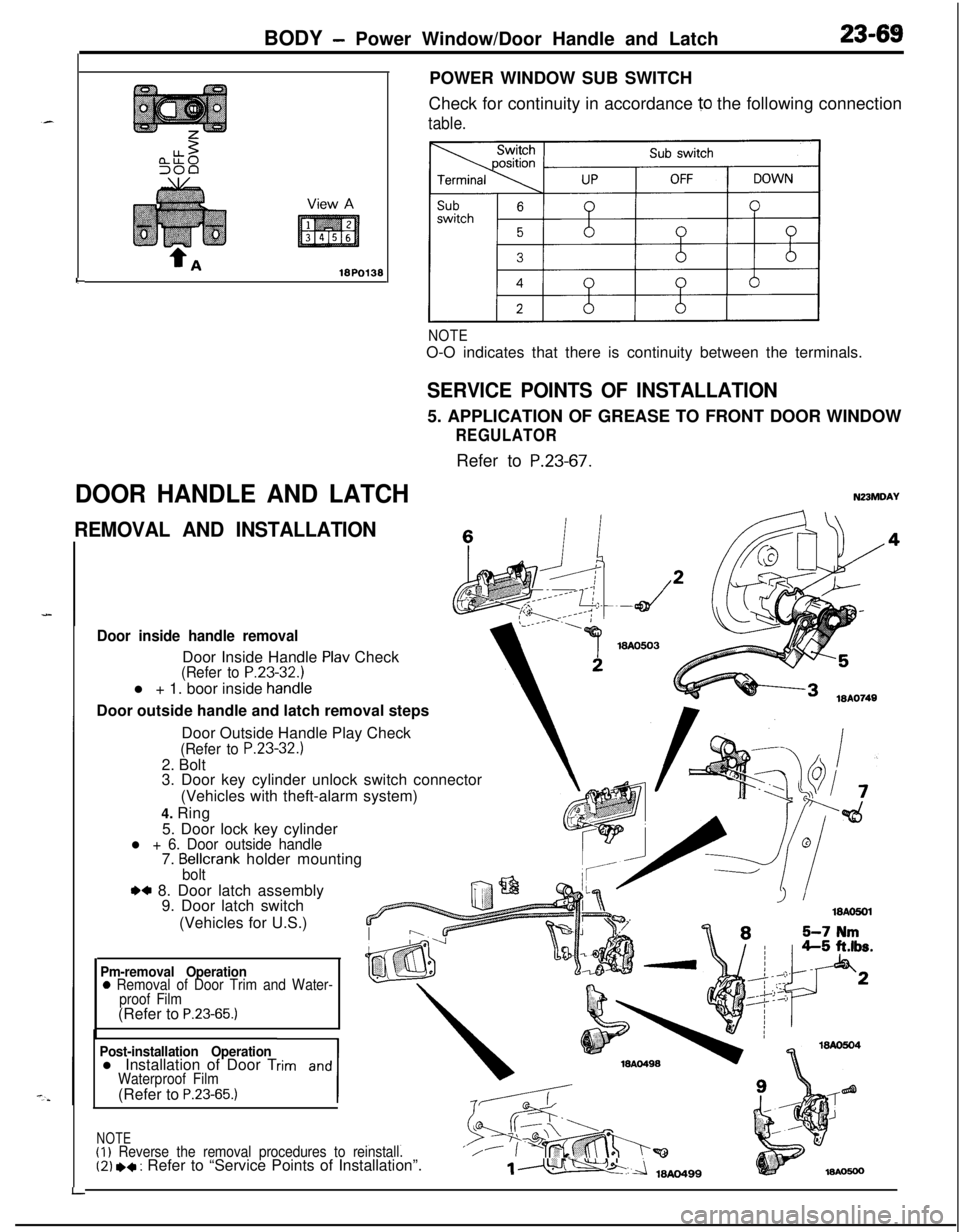
DOOR HANDLE AND LATCHPOWER WINDOW SUB SWITCH
Check for continuity in accordance
10 the following connection
table.
NOTEO-O indicates that there is continuity between the terminals.
SERVICE POINTS OF INSTALLATION5. APPLICATION OF GREASE TO FRONT DOOR WINDOW
REGULATORRefer to
P.23-67.
N23MDAY
REMOVAL AND INSTALLATIONc
Door inside handle removalDoor Inside Handle
Plav Check(Refer to P.23-32.1l + 1. boor inside
handieDoor outside handle and latch removal steps
LDoor Outside Handle Play Check
(Refer to P.23-32.)2. Bolt
3. Door key cylinder unlock switch connector
(Vehicles with theft-alarm system)
4. Ring
5. Door lock key cylinder
l + 6. Door outside handle7. Bellcrank holder mountingbolt
.a 8. Door latch assembly
9. Door latch switch
(Vehicles for U.S.)
Pm-removal Operation0 Removal of Door Trim and Water-
proof Film(Refer to
P.23-65.)
Post-installation Operationl Installation of Door Trim and
1
Waterproof Film(Refer to P.23-65.)
NOTE(I)
Reverse the removal procedures to reinstall.‘/(2) *+ : Refer to “Service Points of Installation”.1m
Page 1114 of 1216

23-70BODY- Door Handle and Latch/Central Door Lockina Svstem
I18AO750 1lBY3611 I.- .--,
!-
II
T!3123
18PO39i
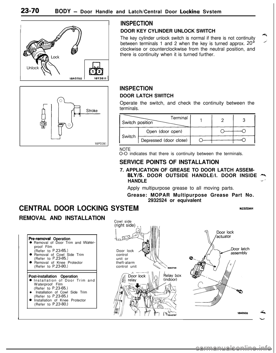
INSPECTIONDOOR KEY CYLINDER UNLOCK SWITCH
The key cylinder unlock switch is normal if there is not continuity7
between terminals 1 and 2 when the key is turned approx. 20”’clockwise or counterclockwise from the neutral position, and
there is continuity when it is turned further.
INSPECTIONDOOR LATCH SWITCH
Operate the switch, and check the continuity between the
terminals.
NOTEO-O indicates that there is continuity between the terminals.
SERVICE POINTS OF INSTALLATION7. APPLICATION OF GREASE TO DOOR LATCH ASSEM-
BLY/5. DOOR OUTSIDE HANDLE/l. DOOR INSIDE rr,
HANDLE.< ‘Apply multipurpose grease to all moving parts.
Grease: MOPAR Multipurpose Grease Part No.
2932524 or equivalent
CENTRAL DOOR LOCKING SYSTEMN23ZDAI-I
REMOVAL AND INSTALLATION
Pre-removal Operation0 Removal of Door Trim and Water-
Iproof Film
(Refer to P.23-65.)
0 Removal of Cowl Side Trim
(Refer to P.23-85.)
0 Removal of Knee Protector
(Refer to P.23-80.)
Post-installation Operation0 Installation of Door Trim and
Waterproof Film
(Refer to P.23-65.)
l Installation of Cowl Side Trim
(Refer to P.23-85.)
0 Installation of Knee Protector
(Refer to P.23-80.)
ICowl side
(right side) , ,
Door lock
control
unit or
theft-alarm
control unit