Page 905 of 1216

AUTOMATIC TRANSAXLE - Service Adjustment Procedures21-21109A0146
OQMOO45
control lever
control lever
5 mm
Section A-A
(2 in.)Manual
controllever
Switch body
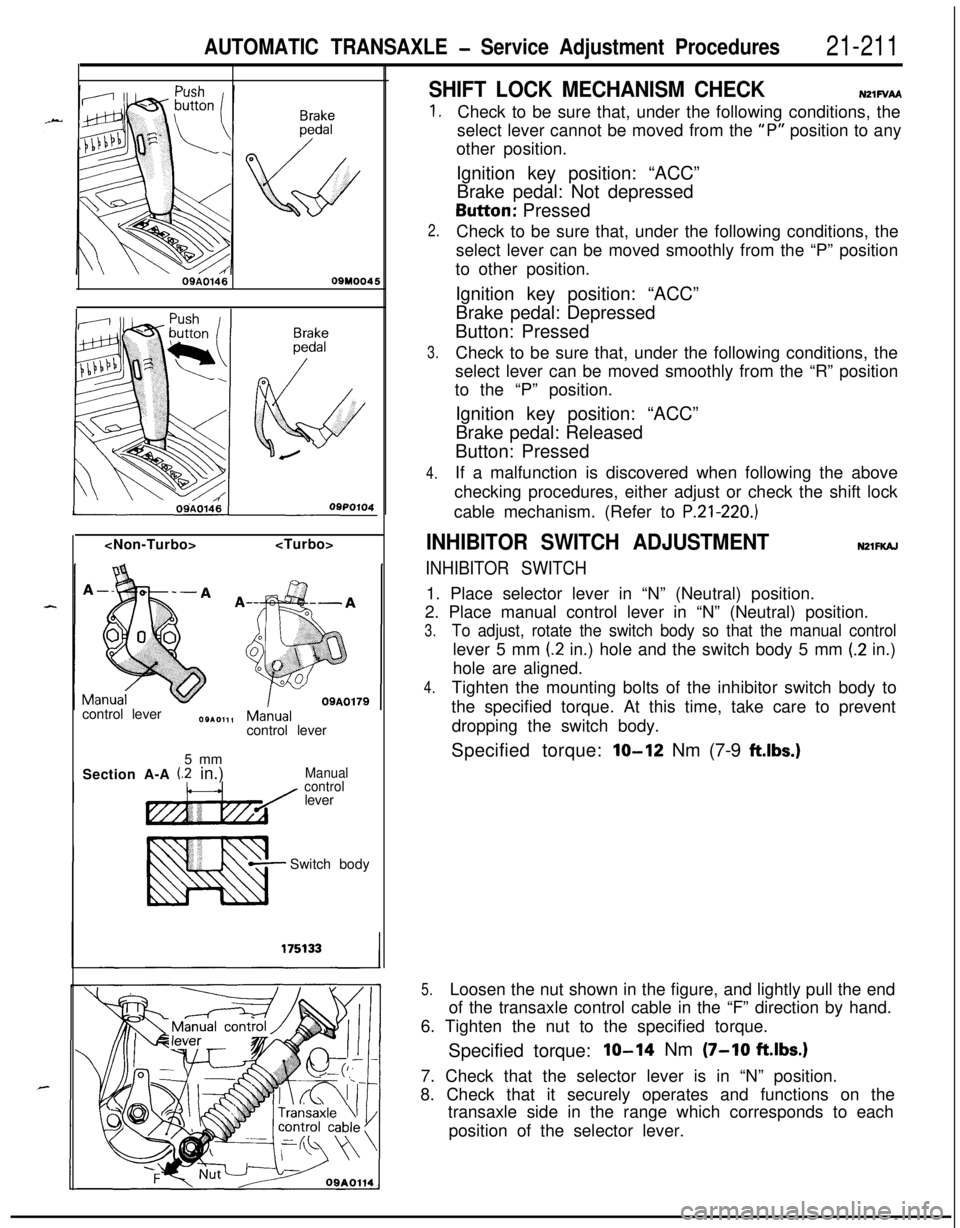
SHIFT LOCK MECHANISM CHECKN21FVAA
1.
2.
3.
4.Check to be sure that, under the following conditions, the
select lever cannot be moved from the
“P” position to any
other position.
Ignition key position: “ACC”
Brake pedal: Not depressedButton: Pressed
Check to be sure that, under the following conditions, the
select lever can be moved smoothly from the “P” position
to other position.
Ignition key position: “ACC”
Brake pedal: Depressed
Button: Pressed
Check to be sure that, under the following conditions, the
select lever can be moved smoothly from the “R” position
to the “P” position.
Ignition key position: “ACC”
Brake pedal: Released
Button: Pressed
If a malfunction is discovered when following the above
checking procedures, either adjust or check the shift lock
cable mechanism. (Refer to
P.21-220.)
INHIBITOR SWITCH ADJUSTMENTNZlFKAJ
INHIBITOR SWITCH1. Place selector lever in “N” (Neutral) position.
2. Place manual control lever in “N” (Neutral) position.
3.To adjust, rotate the switch body so that the manual controllever 5 mm
(2 in.) hole and the switch body 5 mm (.2 in.)
hole are aligned.
4.Tighten the mounting bolts of the inhibitor switch body to
the specified torque. At this time, take care to prevent
dropping the switch body.
Specified torque:
lo-12 Nm (7-9 ftlbs.)
5.Loosen the nut shown in the figure, and lightly pull the end
of the transaxle control cable in the “F” direction by hand.
6. Tighten the nut to the specified torque.
Specified torque:
IO-14 Nm (7-10 ftlbs.)7. Check that the selector lever is in “N” position.
8. Check that it securely operates and functions on the
transaxle side in the range which corresponds to each
position of the selector lever.
Page 910 of 1216
21-216AUTOMATIC TRANSAXLE - Service Adjustment Procedures
I16A0905
SPEEDOMETER CABLE REPLACEMENTN21FEAK2,1. Correctly insert the adapter into the instrument panel, and
+fasten the new speedometer cable.
t,
2.Install the grommet so that, as shown in the illustration, thecable attachment is positioned upward.
Caution
1.The cable arrangement should be made so that the
radius of cable bends is 150 mm (5.9 in.) or more.
2.The arrangement of the speedometer cable should
be such that it does not interfere with other parts.
3. At the transaxle end of the speedometer cable, the key
joint should be inserted into the transaxle, and the nut
should be securely tightened.
Caution
“ccIf the cable is not correctly and securely connected, it
may cause incorrect indication by the speedometer, or
abnormal noise. Be sure to connect it correctly.
Page 911 of 1216
AUTOMATIC TRANSAXLE - Transaxle Control21-217
TRANSAXLE CONTROL
dl_i REMOVAL AND INSTALLATIONNZlub-
-.
lo-14 Nm7-10 ft.lbs.
i284-6
Nm
y-14 Nm7-10 ft.lbs.
Transaxle control cable and selector lever
assembly removal steps
1. Plug2. Side cover (B)3. Power (PWR)/Economy (ECO) switch
4. Side cover(B)
5. Cover(B)
6. Cup holder7. Carpet
8.
EZrreTstion of floor console wiring
9. Guide ring
IO. Shoulder belt 11. Floor console
17. Snap pin18. Key interlock cable (selector lever
assembly side)
23.
S$i; lock cable (selector lever assembly
26. Snap pin27. Clip
28. Adjusting nut
l 4 29. Clip++ 30. Transaxle control cable31. Selector lever assembly
zykeverse the removal procedures to reinstall.(2) l + : Refer to “Service Points of Installation”
Page 912 of 1216

2l-218AUTOMATIC TRANSAXLE - Transaxle Control
724
169-14
Nm7-10 ftlbs.7
\\4-6 Nm3-4 ft.lbs.3-4
ft.lbs.
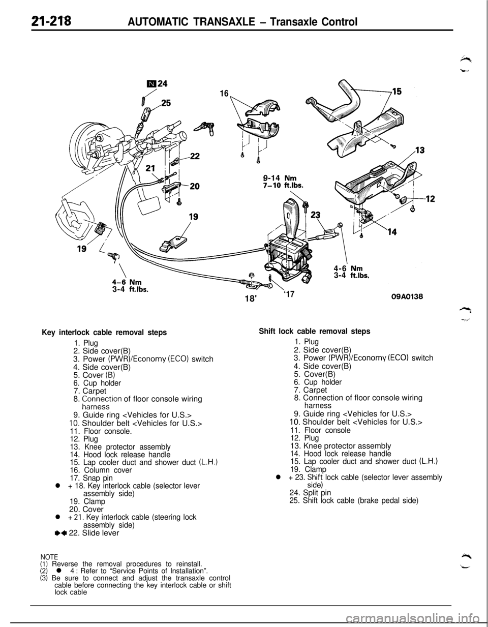
Key interlock cable removal steps
1. Plug2. Side cover(B)
3. Power
(PWR)/Economy (ECO) switch
4. Side cover(B)
5. Cover
(B)6. Cup holder7. Carpet
8.
;ir;eystion of floor console wiring
9. Guide ring
10. Shoulder belt 11. Floor console.
12. Plug
13. Knee protector assembly
14. Hood lock release handle
15. Lap cooler duct and shower duct
(L.H.)16. Column cover
17. Snap pin
l + 18. Key interlock cable (selector lever
assembly side)
19. Clamp20. Cover
l + 21, Key interlock cable (steering lock
assembly side)
e+ 22. Slide lever
NOTE(I) Reverse the removal procedures to reinstall.(2) l 4 : Refer to “Service Points of Installation”.(3) Be sure to connect and adjust the transaxle control
cable before connecting the key interlock cable or shift
lock cable18'
‘1709A0138
Shift lock cable removal steps
1. Plug2. Side cover(B)
3. Power
(PWR)/Economv (EC01 switch
4. Side cover(B)
’5. Cover(B)
6. Cup holder7. Carpet
8. Connection of floor console wiring
harness9. Guide ring
10. Shoulder belt
11. Floor console
12. Plug13. Knee protector assembly
14. Hood lock release handle
15. Lap cooler duct and shower duct (L.H.)19. Clamp
l + 23. :izs lock cable (selector lever assembly24. Split pin
25. Shift lock cable (brake pedal side)
Page 914 of 1216

AUTOMATIC TRANSAXLE - Transaxle Control
:lemotJnt
\\ \09R0058
09AO143
/’
\
’ CoverCoverKey interlock cableOSA0125
OSAO12629. INSTALLATION OF CLIP
When connecting the control cable to the transaxle mount
,-bracket, install the clip until it contacts the control cable, in
the position shown in the figure.
,”l ADJUSTMENT OF TRANSAXLE CONTROL CABLE
Refer to the section concerning adjustment of the inhibitor
switch. (Refer to P.21-211.)
23. INSTALLATION OF SHIFT LOCK CABLE (SELECT LEVERASSEMBLY SIDE)
(1) Move the select lever to the “R” position.
(2) Clamp the shift lock cable.
(3) Connect the shift lock cable to the select lever
assembly, and temporarily tighten the nut.
(4) Slide the shift lock cable so that the distance between
the select lever assembly’s detent pin and the end of
the shift lock cable is the standard value, and then
tighten the nut at the specified torque.
Standard value (A):
l-4 mm (.04-.I5 in.)
(5) After connecting the shift lock cable, check the shift
lock mechanism. (Refer to P.21-211.)
22. INSTALLATION OF THE SLIDE LEVERI21. KEY INTER-
LOCK CABLE (STEERING LOCK ASSEMBLY SIDE)
(1) With the ignition key either at the “LOCK” position or
removed, install the slide lever to the key cylinder.
(2) Connect, as shown in the figure, the key interlock cable
to the slide lever and the key cylinder.
(3) Apply a light coating of multipurpose grease where
shown in the figure.
Grease: MOPAR Multi-mileage Lubricant Part
No. 2525035 or equivalent
(4) Install the key interlock cable.
18. INSTALLATION OF KEY INTERLOCK CABLE (SELECT
LEVER ASSEMBLY SIDE)
(1) Move the select lever to the “P” postion.(2) Connect the key interlock cable to the select lever
assembly’s lock cam. Be sure that the spring installed
to the key interlock cable is as shown in the figure.
*(3) While gently pressing the lock cam in the
F direction,-tighten the nut to secure the key interlock cable.
(4) After connecting the key interlock cable, check the key
interlock mechanism. (Refer to ‘P.21-210.)
Page 1058 of 1216
23-14BODY - Troubleshooting
ELECTRIC REMOTE CONTROLLED MIRROR
CIRCUIT DIAGRAM
REMOTE&;;NT;LLED
SWITCH
MS-AC-UlSW-NC
L\/\I7
F
cl,,C
F
#
E-59
IpJJ%J
\/
3‘9g
4t
5
IL
;,,5 E-57m.--
!3
E-63
[z
J/BE-03
II
(LEFT SIDE)(RIGHT SIDE)LJt
REMOTE CONTROL MIRROR
1
-
i'
E-57
N23EBBD
OPERATIONl When the remote controlled mirror switch is
operated while the ignition key is in “ACC” or“ON” position, current flows through fuse No.@ remote controlled mirror switch, remote
con-trolled mirror, remote controlled mirror switch,
and ground, causing the mirror to move.
TROUBLESHOOTING HINTSNeither right nor left mirror operates
1) Also cigarette lighter does not operate0 Check fuse.
2) Cigarette lighter operates
l Check remote controlled mirror switch.
Page 1059 of 1216
c
BODY - Troubleshooting2345
IUZZER < Vechicles for Canada >
CIRCUIT DIAGRAMIGNITION
J/B0
10A
c-37x
El34
SEAT BELT
TIMER
'ITCH(IG1)
1OA
y4 C-52
/
WHEN KEYIS REMOVED4,
II
I
I
I
I
I
IIII
I
I
II
I
I
I
I
IIIIIII
.
6
I=3?;IWELTBUZZER
\\ (B)
"4
J/B\I
"5 c-54
WITH
R!Ei&-ESTEM
DIODE
E-52
91FRONT DOOR SWITCH
cu(LEFT SIDE)
N23EBABa
KX35-AC-UlblB-NC
Page 1060 of 1216

23-16BODY - Troubleshooting
OPERATION
Key-reminder warning0 Battery voltage is always supplied, through sub
fusible link No.
@, to the key-reminder switch.0 When the driver’s seat door is opened while the
ignition key is still in the key cylinder, the door
switch is switched ON, electricity flows to sub
fusible link No.
0, the key-reminder switch, the
buzzer, the door switch, and ground, and the
buzzer sounds.
Seat belt warning0 Battery voltage is applied, through fuse No.
0,to the seat belt timer when the ignition key is at
the “ON” position.0 Electricity flows to sub fusible link No. @, the
key-reminder switch, the seat belt warning light,
the seat belt timer, and ground, and the seat beltwarning light illuminates for approx. 6 seconds.0
If the driver does not buckle the seat belt, the seatbelt switch is switched ON, electricity flows to
sub fusible link No. @, the key-reminder switch,the buzzer, the seat belt switch, the seat belt
warning timer, and ground, and the buzzer
sounds for approx. 6 seconds.0 When the driver buckles the seat belt, the seat
belt switch is switched OFF and the buzzer stops.
TROUBLESHOOTING HINTS
Key-reminder warningThe key-reminder warning doesn’t sound.
(1) The seat belt warning function is OK.
l Check the door switch.
(2) The seat belt warning also doesn’t function.0 Check the buzzer.
Seat belt warning1. The seat belt warning doesn’t function.
(1) The seat belt warning light illuminates.0 Check the seat belt switch.
(2) The seat belt warning light also does not
function (but the key-reminder warning
functions normally. 10 Check the seat belt timer.
(3) The seat belt warning light also does not
function (and the key-reminder warning also
does not function).0 Check the key-reminder switch.
2.The buzzer doesn’t stop even though the driver’s
seat belt has been buckled.0 Check the seat belt switch.
3.The seat belt warning light doesn’t illuminate (but
the buzzer sounds).l Check the light bulb.
’ I