Page 662 of 1216

19-14STEERING - Service Adjustment Procedures < Power Steering >Shut-off valv
Pressure gauge
(FW close)
(C-3309-E)I
Temperature
gauge
\e’\
Pressure hoses
Re(Mti990994)
\Oil pump
713AO145Shut-off valve
Pressure gauge(FullY ?penl
Pressure hoses
OIL PUMP PRESSURE TESTNl9FlAF
CHECKING THE OIL PUMP RELIEF PRESSURE1. Disconnect the pressure hose from the oil pump, and then
connect the special tools.
2.Bleed the air, and then turn the steering wheel several timeswhile the vehicle is not moving so that the temperature of
the fluid rises to approximately
50-60°C (122-14OOF).3. Start the engine and idle it at 1,000
f 100 rpm.
4. Fully close the shut-off valve of the pressure gauge and
measure the oil pump relief pressure to confirm that it is
within the standard value range.
Standard value: 7.5-8.2
MPa (1,067-1,166 psi)
Caution
Pressure gauge shut off valve must not remain closed formore than 10 seconds.
5.If it is not within the standard value, overhaul the oil pump.
6.Remove the special tools, and then tighten the pressure hoseto the specified torque.
7. Bleed the system.
CHECKING THE PRESSURE UNDER NO-LOAD CONDITIONS1. Disconnect the pressure hose from the oil pump, and then
connect the special tool.
2.Bleed the air, and then turn the steering wheel several timeswhile the vehicle is not moving so that the temperature of
the fluid rises to approximately
50-60°C (122-14OOF).3. Start the engine and idle it at 1,000
-t 100 rpm.
4.
Check whether or not the hydraulic pressure is the standard
value when no-load conditions are created by fully openingthe shut-off valve of the pressure gauge.
Standard value:
0.8-I .O MPa (114-142 psi)
Limit: 1.5
MPa (213 psi)
5. If it is not within the standard value, the probable cause is
a malfunction of the oil line or steering gear box, so check
these parts and repair as necessary.
6.Remove the special tools, and then tighten the pressure hoseto the specified torque.
7. Bleed the system.
Page 663 of 1216

-
c. .
STEERING - Service Adiustment Procedures 3:945
Shut-off valve
Pressure gauge
CHECKING THE STEERING GEAR PETENTION HYDRAULIC
PRESSURE1. Disconnect the pressure hose from the oil
pbmd, and iheh
connect the special tools.
2.Bleed the air, and then turn the steering wheel several timeswhile the vehicle is not moving so that the temperature of
the fluid rises to approximately
50~60OC (122~14pyF).
3. ‘Start the engine and idle it at 1,000 +
100 rem: .‘,’.
4.Fully close and fully open the shut-off valve of the pressure
gauge.
5.Turn the steering wheel all the way to the left or right; then
check whether or not the retention hydraulic pressure is the
standard value.
Standard value: 7.5-8.2 MPa (1,067-1,166 psi)6. When not within the standard value, overhaul the steering
gear box.
Remeasure fluid pressure.
7.Remove the special tools, and then tighten the pressure hoseto the specified torque.
8. Bleed the system.
OIL PRESSURE SWITCH CHECKNlSFUAB1. Disconnect the pressure hose from the oil pump, and then
connect the special tools.
2.Bleed the air, and then turn the steering wheel several timeswhile the vehicle is not moving so that the temperature of
the fluid rises to approximately
50-60°C (122-14OOF).3. The engine should be idling.
4. Disconnect the connector for the oil pressure switch, and
place an ohmmeter ,in position.
5.Gradually close the shut-off valve of the pressure gauge andincrease the hydraulic pressure then check whether the
hydraulic pressure that activates the switch is the standard
value.
Standard value: 1.5-2.0 MPa (213-284 psi)
6. Gradually open the shut-off valve and reduce the hydraulic
pressure; then check whether the hydraulic pressure that
deactivates the switch is the standard value.
Standard value: 0.7-1.2 MPa (100-171 psi)
7.Remove the special tools, and then tighten the pressure hoseto the specified torque.
8. Bleed the system.
Page 896 of 1216

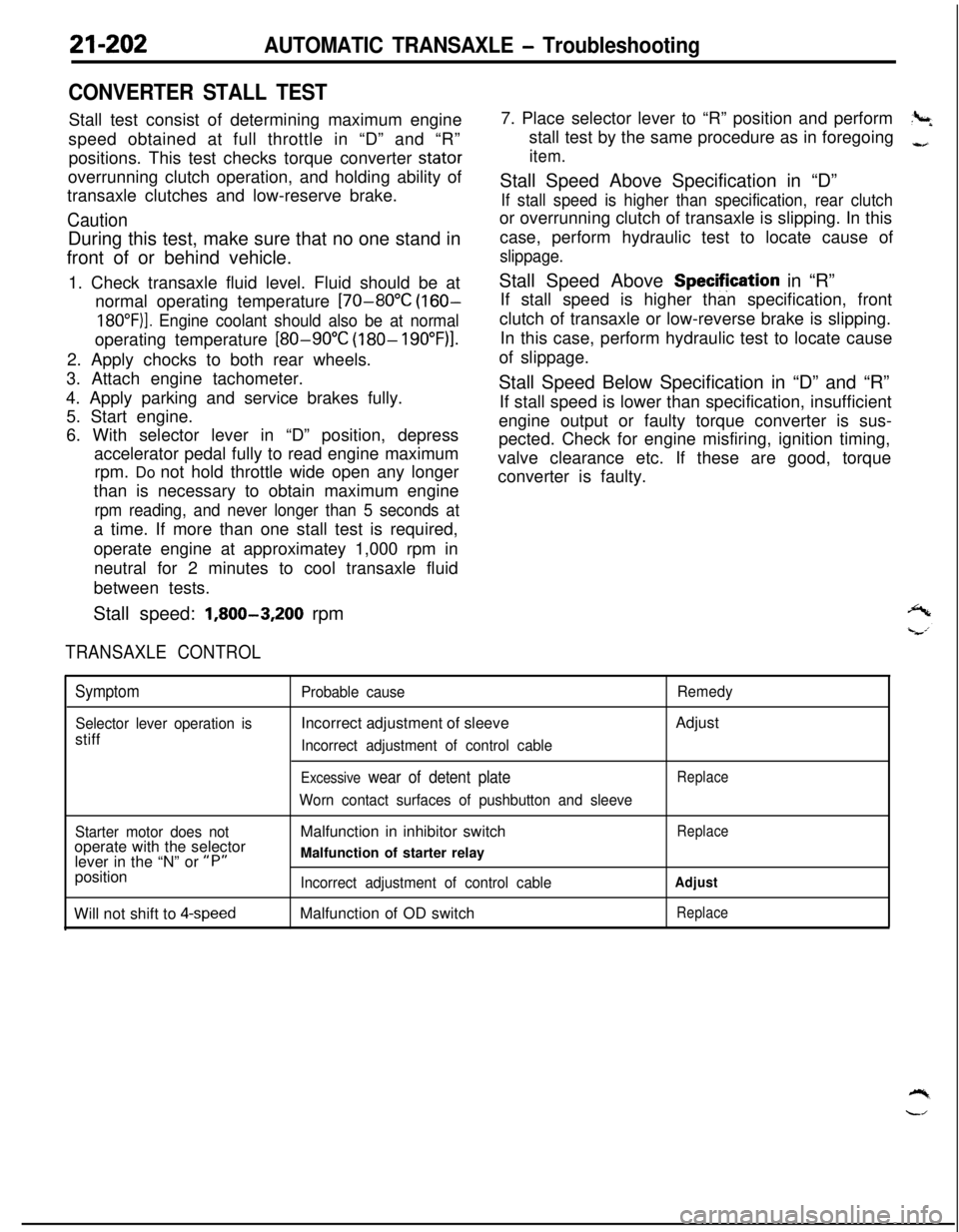
21-202AUTOMATIC TRANSAXLE - Troubleshooting
CONVERTER STALL TESTStall test consist of determining maximum engine
speed obtained at full throttle in “D” and “R”
positions. This test checks torque converter stator
overrunning clutch operation, and holding ability of
transaxle clutches and low-reserve brake.
CautionDuring this test, make sure that no one stand in
front of or behind vehicle.
1. Check transaxle fluid level. Fluid should be at
normal operating temperature
[70-80°C (160-
18O”F)]. Engine coolant should also be at normaloperating temperature
[80-90°C (180- 19O”F)l.2. Apply chocks to both rear wheels.
3. Attach engine tachometer.
4. Apply parking and service brakes fully.
5. Start engine.
6. With selector lever in “D” position, depress
accelerator pedal fully to read engine maximum
rpm. Do not hold throttle wide open any longer
than is necessary to obtain maximum engine
rpm reading, and never longer than 5 seconds ata time. If more than one stall test is required,
operate engine at approximatey 1,000 rpm in
neutral for 2 minutes to cool transaxle fluid
between tests.
Stall speed:
1,800-3,200 rpm
TRANSAXLE CONTROL7. Place selector lever to “R” position and perform
?+stall test by the same procedure as in foregoing
-,
item.Stall Speed Above Specification in “D”
If stall speed is higher than specification, rear clutchor overrunning clutch of transaxle is slipping. In this
case, perform hydraulic test to locate cause of
slippage.Stall Speed Above Specifjcation in “R”
If stall speed is higher than specification, front
clutch of transaxle or low-reverse brake is slipping.
In this case, perform hydraulic test to locate cause
of slippage.
Stall Speed Below Specification in “D” and “R”
If stall speed is lower than specification, insufficient
engine output or faulty torque converter is sus-
pected. Check for engine misfiring, ignition timing,
valve clearance etc. If these are good, torque
converter is faulty.
Symptom
Selector lever operation isstiff
Probable causeIncorrect adjustment of sleeve
Incorrect adjustment of control cable
Excessive wear of detent plate
Worn contact surfaces of pushbutton and sleeveRemedyAdjust
Replace
Starter motor does notoperate with the selector
lever in the “N” or
“P”position
Will not shift to
4-speedMalfunction in inhibitor switch
Malfunction of starter relay
Incorrect adjustment of control cableMalfunction of OD switch
Replace
Adjust
Replace
Page 1039 of 1216
22-l-.
WHEELS
AND TIRES
CONTENTSNZZAA-
SERVICE ADJUSTMENT PROCEDURES.......4TROUBLESHOOTING......................................3
Tire
InflationPressureCheck......................4Bald Spots
TireWearCheck..........................................4Cracked Treads
Wheel
RunoutCheck...................................4Feathered Edge
SPECIFICATIONSRapid Wear at Center.............................................2
General
Specifications..................................2Rapid Wear at Shoulders
ServiceSpecificationsScalloped Wear...................................2Wear on One Side
7TorqueSpecifications...................................2
WHEEL AND TIRE..........................................5
Page 1040 of 1216

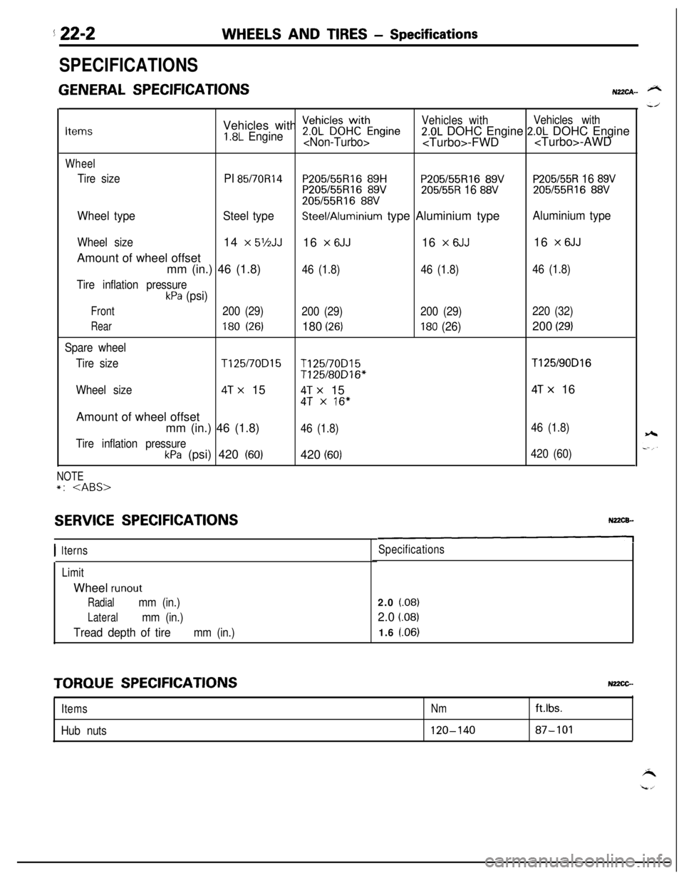
5 22-2WHEELS AND TIRES - Specifications
SPECIFICATIONS
GENERAL SPECIFICATIONSN22CA- @NVehicles with
~eDhL”~~HWCthEngineVehicles withVehicles withItems1.8L Engine2.0L DOHC Engine 2.0L DOHC Engine-FWD-AWD
Wheel
Tire sizePI 85/70R14P205155Rl6 89HP205/55R16 89VP205/55R 16 89VP205155R16 89V205/55R 16 88V205/55R16 88V
205/55R16 88V
Wheel typeSteel typeSteel/Aluminium type Aluminium typeAluminium type
Wheel size14 x 5’/2JJ16 x 6JJ16 x 6JJ16 x 6JJAmount of wheel offset
mm (in.) 46 (1.8)
46 (1.8)46 (1.8)46 (1.8)
Tire inflation pressure
kPa (psi)
Front200 (29)
200 (29)200 (29)220 (32)
Rear180 (26)180 (26)180 (26)200 (29)
Spare wheel
Tire size
T125/70D15T125/70D15T125/90D16
T125/80D16*
Wheel size
4T x 154T x 154T x 16
4T x 16”Amount of wheel offset
mm (in.) 46 (1.8)
46 (1.8)46 (1.8)
Tire inflation pressure
kPa (psi) 420 (60)420 (60)420 (60)
NOTE*:
SERVICE SPECIFICATIONS
I 1terns
LimitWheel
runout
Radialmm (in.)
Lateralmm (in.)
Tread depth of tiremm (in.)
Specifications2.0
(.08)2.0
i.08)1.6 l.06)
TORQUE SPECIFICATIONSNz2cG-
ItemsNm
Hub nuts120-140ftlbs.87-101