Page 552 of 1216

14-98FUEL SYSTEM -Fuel Tank 01
W636
Positioning projection03AO257
\03A0256SERVICE POINTS OF REMOVAL
N14G6AHl6. DISCONNECTION OF HIGH PRESSURE FUEL
HGSECaution
Cover the hose connection with rags to prevent splash
of fuel that could be caused by some residual pressure
in the fuel pipe line.
INSPECTIONN14GCAHl Check the hoses and the pipes for crack or damage.
l Check the fuel tank cap for malfunction.
l Check the fuel tank for deformation, corrosion or crack.
l Check the fuel tank for dust or foreign material.
NOTE
If the inside of the fuel tank is to be cleaned, use any one ofthe following:
(1) Kerosene
(2) Trichloroethylene
(3) A neutral emulsion type detergent
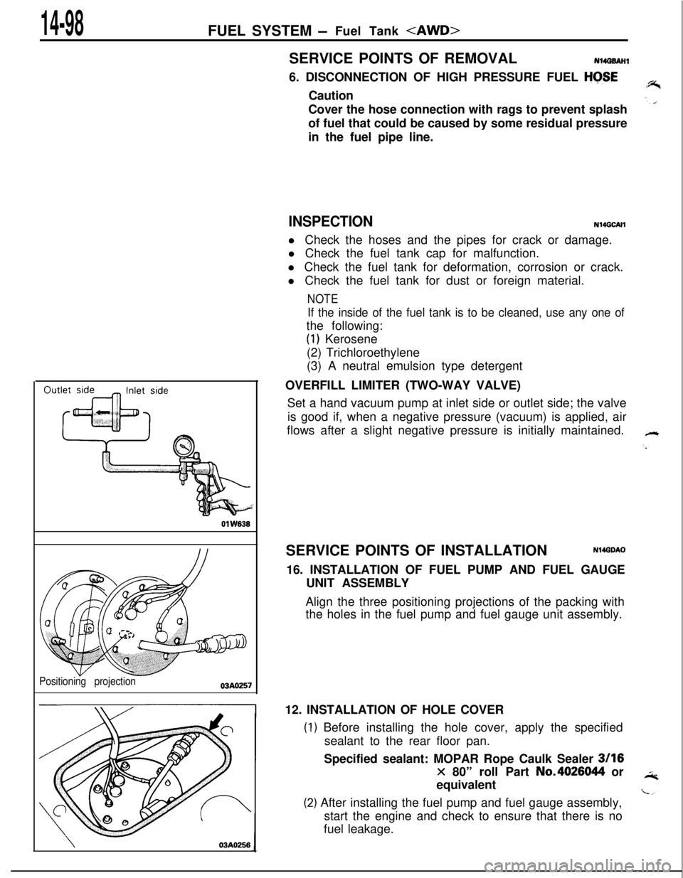
OVERFILL LIMITER (TWO-WAY VALVE)
Set a hand vacuum pump at inlet side or outlet side; the valve
is good if, when a negative pressure (vacuum) is applied, air
flows after a slight negative pressure is initially maintained.
SERVICE POINTS OF INSTALLATION
N14GDAO16. INSTALLATION OF FUEL PUMP AND FUEL GAUGE
UNIT ASSEMBLY
Align the three positioning projections of the packing with
the holes in the fuel pump and fuel gauge unit assembly.
12. INSTALLATION OF HOLE COVER
) Before installing the hole cover, apply the specified
sealant to the rear floor pan.
Specified sealant: MOPAR Rope Caulk Sealer
3116
x 80” roll Part No.4026044 or
equivalent
!) After installing the fuel pump and fuel gauge assembly,
start the engine and check to ensure that there is no
fuel leakage.
Page 558 of 1216

FUEL SYSTEM - Fuel Line and VaDor Line/Fuel Filter
High-pressur
hose
f+-----Eye bolt
Gasket
Fuel filter
Flare nut
Fuel main
pipe
\-Apply engine
&ring Oi’
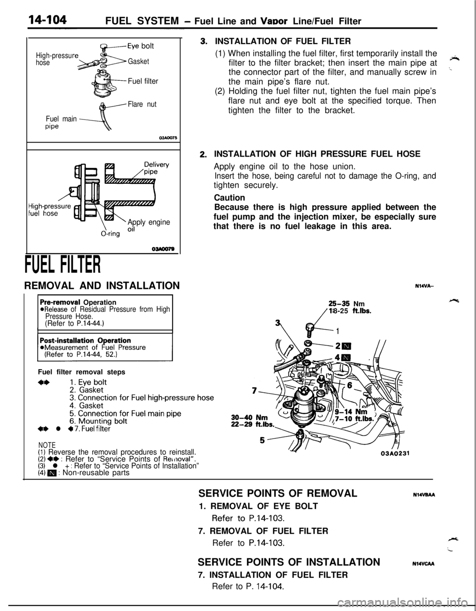
FUEL FILTERREMOVAL AND INSTALLATION3.2.INSTALLATION OF FUEL FILTER
(1) When installing the fuel filter, first temporarily install the
filter to the filter bracket; then insert the main pipe at
‘*the connector part of the filter, and manually screw in
..the main pipe’s flare nut.
(2) Holding the fuel filter nut, tighten the fuel main pipe’s
flare nut and eye bolt at the specified torque. Then
tighten the filter to the bracket.
Pre-removal Operation@Release of Residual Pressure from High
Pressure Hose.
(Refer to P.14-44.)IIFuel filter removal steps
**1. Eye bolt2. Gasket3. Connection for Fuel high-pressure hose
4. Gasket
5. Connection for Fuel main pipe6. Mounting bolt+e l 4 7. Fuel filter
NOTE(1) Reverse the removal procedures to reinstall.(2) +e : Refer to “Service Points of Removal”.(3) l + : Refer to “Service Points of Installation”(4) m : Non-reusable partsINSTALLATION OF HIGH PRESSURE FUEL HOSE
Apply engine oil to the hose union.
Insert the hose, being careful not to damage the O-ring, andtighten securely.
Caution
Because there is high pressure applied between the
fuel pump and the injection mixer, be especially sure
that there is no fuel leakage in this area.
N14VA-25-35 Nm
18-25
ft.lbs.
vd-
7’
1
Y03A0231SERVICE POINTS OF REMOVAL
NlIVBAA1. REMOVAL OF EYE BOLT
Refer to P.14-103.
7. REMOVAL OF FUEL FILTER
Refer to
P.14-103.SERVICE POINTS OF INSTALLATION
7. INSTALLATION OF FUEL FILTER
Refer to P. 14-104.
N14VCAA
Page 559 of 1216

ENGINE CONTROL - SpecificatiodTroubleshooting
ENGINE CONTROL
-.
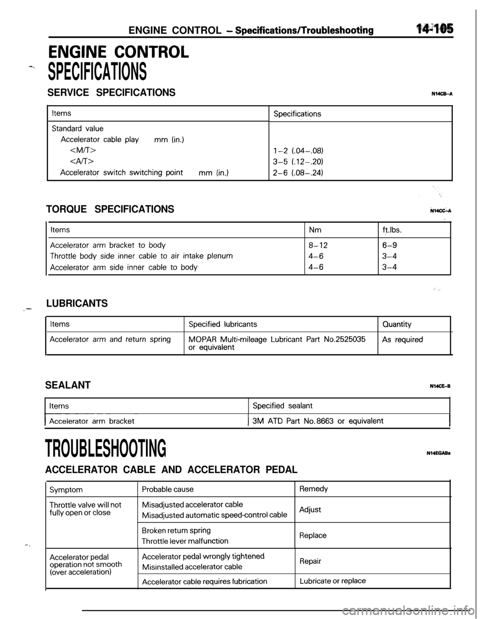
SPECIFICATIONS
SERVICE SPECIFICATIONSN14CEA
Items
Standard value
Accelerator cable playmm (in.)
dfi>
Accelerator switch switching pointmm (in.)Specifications
1-2 (.04-.08)
3-5 (.12-.20)
2-6 (.08-.24)
N14CkATORQUE SPECIFICATIONS
Items
Accelerator arm bracket to body
Throttle body side inner cable to air intake plenum
Accelerator arm side inner cable to body
Nmft.lbs.
8-126-9
4-63-4
4-63-4
I
: j,
LUBRICANTS_-
Items
Accelerator arm and return spring
Specified lubricants
MOPAR Multi-mileage Lubricant Part No.2525035
or equivalentQuantityAs required
SEALANTN14CE.-BItems
I-- ~Accelerator arm bracket
Specified sealant
I3M ATD Part No.8663 or equivalentI
-.
TROUBLESHOOTINGN14EGABa
ACCELERATOR CABLE AND ACCELERATOR PEDAL
Symptom
Throttle valve will notfully
open or close
Probable causeRemedyMisadjusted
accelerator cableMisadjusted automatic
speed-control cableAdjust
Broken return springThrottle
lever malfunctionReplace
Accelerator pedaloperation not smooth(over acceleration)
Accelerator pedal wrongly tightenedMisinstalled
accelerator cable
Accelerator cable requires lubrication
Repair
Lubricate or replace
Page 560 of 1216

14-106ENGINE CONTROL - Service Adjustment Procedures
TAir intakeAdjusting bolts
Idle switch03A,,2.8
07RQ024L
I
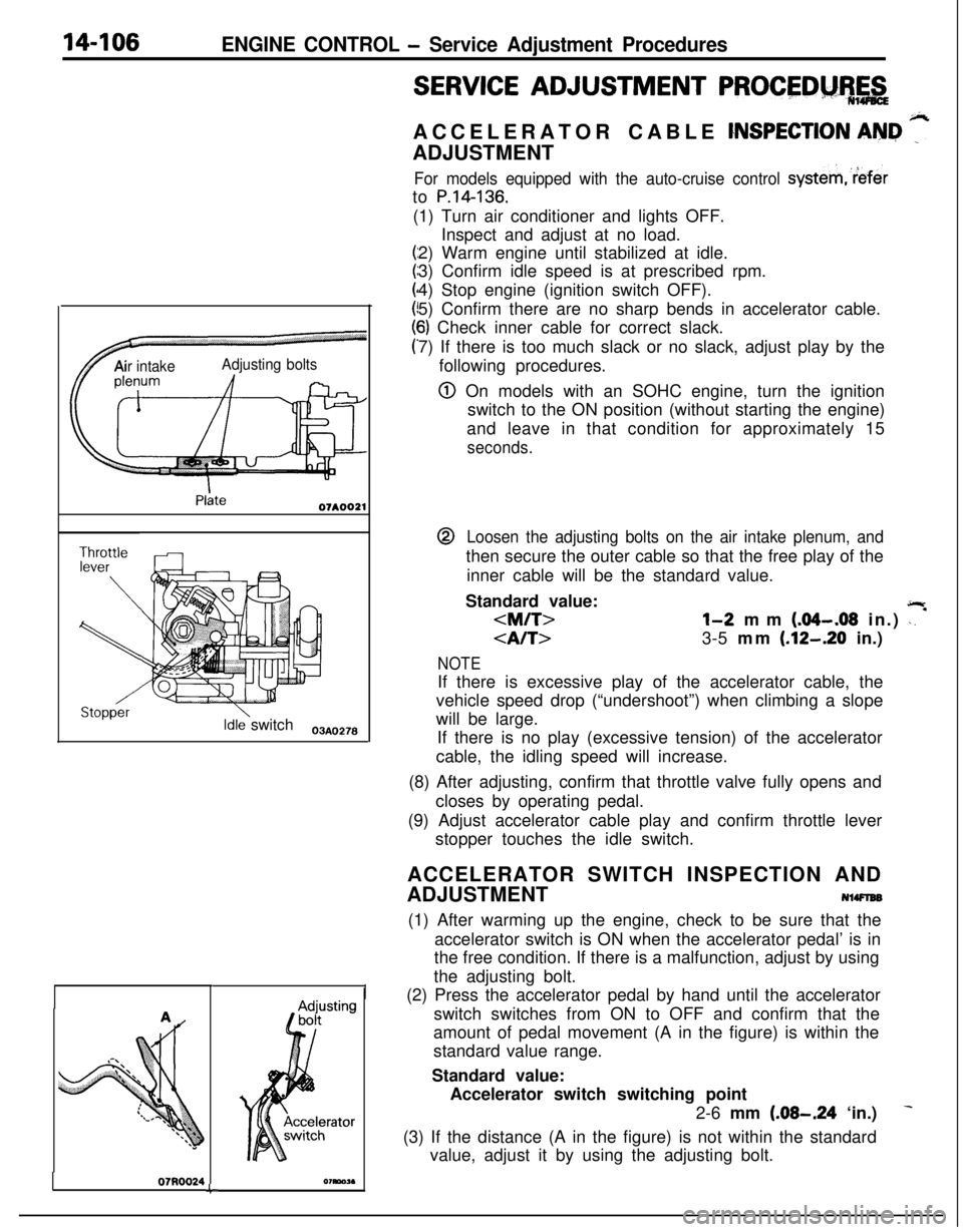
SERVICE ADJUSTMENT PROCEDM%,&ACCELERATOR CABLE
CNSPECTION AN&I ”ADJUSTMENT
For models equipped with the auto-cruise control systemreferto
P.14-136.(1) Turn air conditioner and lights OFF.
Inspect and adjust at no load.
2) Warm engine until stabilized at idle.
3) Confirm idle speed is at prescribed rpm.
4) Stop engine (ignition switch OFF).
5) Confirm there are no sharp bends in accelerator cable.
6) Check inner cable for correct slack.
7) If there is too much slack or no slack, adjust play by the
following procedures.
@ On models with an SOHC engine, turn the ignition
switch to the ON position (without starting the engine)
and leave in that condition for approximately 15
seconds.@
Loosen the adjusting bolts on the air intake plenum, andthen secure the outer cable so that the free play of the
inner cable will be the standard value.
Standard value:
jlr
l-2 mm (.04-.08 in.) \. *
3-5 mm (.12-.20 in.)
NOTEIf there is excessive play of the accelerator cable, the
vehicle speed drop (“undershoot”) when climbing a slope
will be large.
If there is no play (excessive tension) of the accelerator
cable, the idling speed will increase.
(8) After adjusting, confirm that throttle valve fully opens and
closes by operating pedal.
(9) Adjust accelerator cable play and confirm throttle lever
stopper touches the idle switch.
ACCELERATOR SWITCH INSPECTION AND
ADJUSTMENT
NlWlEB(1) After warming up the engine, check to be sure that the
accelerator switch is ON when the accelerator pedal’ is in
the free condition. If there is a malfunction, adjust by using
the adjusting bolt.
(2) Press the accelerator pedal by hand until the accelerator
switch switches from ON to OFF and confirm that the
amount of pedal movement (A in the figure) is within the
standard value range.
Standard value:
Accelerator switch switching point
2-6 mm
(.08-.24 ‘in.)
(3) If the distance (A in the figure) is not within the standard
value, adjust it by using the adjusting bolt.
Page 561 of 1216
Page 562 of 1216

14-108ENGINE CONTROL - Engine Control
INSPECTION
j N%PJCf@l Check the inner and outer cable for damage.
l Check the cable for smooth movement.$+
l Check the accelerator arm for bending.--
l Check the return spring for deterioration.
l Check the connection of bushing to end metal fitting.
l Check the accelerator switch for ON/OFF switching.
SERVICE POINTS OF INSTALLATIONN14DDAP
ll.APPLlCATlON OF GREASE TO RETURN SPRING/
10. ACCELERATOR ARM
Apply multipurpose grease around the each moving point
of the accelerator arm.
Grease: MOPAR Multi-mileage Lubricant
Part No.2525035 or equivalent
8. APPLICATION OF SEALANT TO ACCELERATOR ARM
BRACKETApply the specified sealant to the bolt mounting hole, and
then tighten the accelerator arm bracket.
,%Specified sealant:
3M ATD Part No.8663 or equivalent
4. APPLICATION OF GREASE TO ACCELERATOR ARM
SIDE INNER CABLE/B. BUSHING
(1) Securely install the resin bushing of the accelerator
cable on the end of the accelerator arm.
(2) Apply multipurpose grease around the cable end.
Grease: MOPAR Multi-mileage Lubricant
Part No.2525035 or equivalent
Page 574 of 1216
14-120AUTO-CRUISE CONTROL SYSTEM - Troubleshooting
11. CHECKING THE THROTTLE POSITION SENSOR AND IDLE SWITCH CIRCUIT<1.8L Engine>
Throttle
position
sensor
MPI controlunitnw374<2.0L DOHC Engine>
ruiseI unitDescription of operation
“s
The throttle position sensor and idle switch are mounted in the,
motor position sensor or throttle body and are sensors in theMPI system. The idle switch is turned OFF when the accelera-
tor pedal is pressed and ON when it is released. In addition,
throttle position sensor output voltage varies according to thedegree of opening of the throttle valve.Troubleshooting hint
Diagnosis-No. 17
Diagnosis-No. 17
ECU terminal voltageTeKlna’
SignalConditionsTerminal
voltage
4Idle switchWhen accelerator
pedal is pressedXFgr
When acceleratorovpedal is released
5ThrottleWhen accelerator 4.OV-5.5V
position sensorpedal is pressedall the way down
When accelerator 0.48-0.72Vpedal is released
Page 579 of 1216