1991 MITSUBISHI ECLIPSE electric
[x] Cancel search: electricPage 1058 of 1216
23-14BODY - Troubleshooting
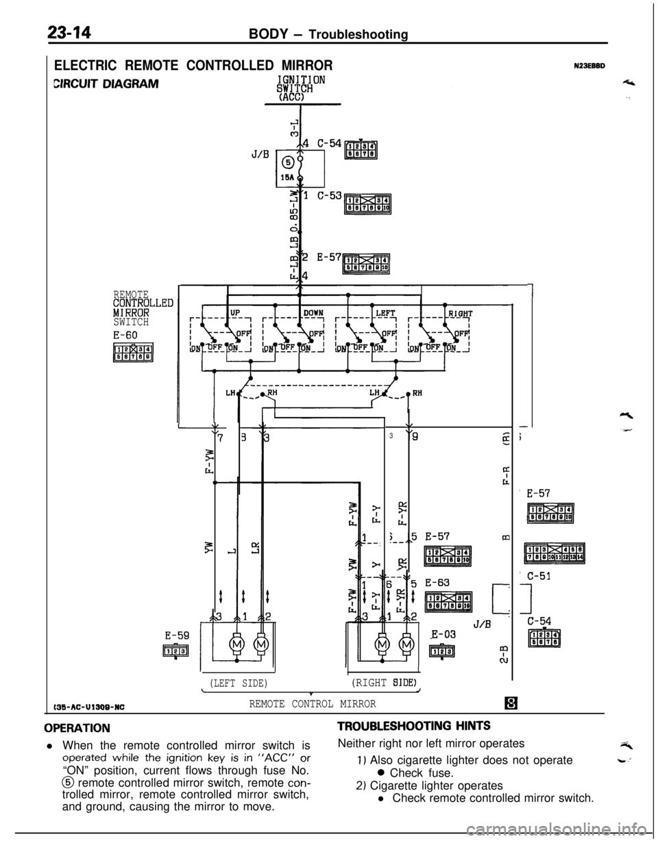
ELECTRIC REMOTE CONTROLLED MIRROR
CIRCUIT DIAGRAM
REMOTE&;;NT;LLED
SWITCH
MS-AC-UlSW-NC
L\/\I7
F
cl,,C
F
#
E-59
IpJJ%J
\/
3‘9g
4t
5
IL
;,,5 E-57m.--
!3
E-63
[z
J/BE-03
II
(LEFT SIDE)(RIGHT SIDE)LJt
REMOTE CONTROL MIRROR
1
-
i'
E-57
N23EBBD
OPERATIONl When the remote controlled mirror switch is
operated while the ignition key is in “ACC” or“ON” position, current flows through fuse No.@ remote controlled mirror switch, remote
con-trolled mirror, remote controlled mirror switch,
and ground, causing the mirror to move.
TROUBLESHOOTING HINTSNeither right nor left mirror operates
1) Also cigarette lighter does not operate0 Check fuse.
2) Cigarette lighter operates
l Check remote controlled mirror switch.
Page 1060 of 1216
23-16BODY - Troubleshooting
OPERATION
Key-reminder warning0 Battery voltage is always supplied, through sub
fusible link No.
@, to the key-reminder switch.0 When the driver’s seat door is opened while the
ignition key is still in the key cylinder, the door
switch is switched ON, electricity flows to sub
fusible link No.
0, the key-reminder switch, the
buzzer, the door switch, and ground, and the
buzzer sounds.
Seat belt warning0 Battery voltage is applied, through fuse No.
0,to the seat belt timer when the ignition key is at
the “ON” position.0 Electricity flows to sub fusible link No. @, the
key-reminder switch, the seat belt warning light,
the seat belt timer, and ground, and the seat beltwarning light illuminates for approx. 6 seconds.0
If the driver does not buckle the seat belt, the seatbelt switch is switched ON, electricity flows to
sub fusible link No. @, the key-reminder switch,the buzzer, the seat belt switch, the seat belt
warning timer, and ground, and the buzzer
sounds for approx. 6 seconds.0 When the driver buckles the seat belt, the seat
belt switch is switched OFF and the buzzer stops.
TROUBLESHOOTING HINTS
Key-reminder warningThe key-reminder warning doesn’t sound.
(1) The seat belt warning function is OK.
l Check the door switch.
(2) The seat belt warning also doesn’t function.0 Check the buzzer.
Seat belt warning1. The seat belt warning doesn’t function.
(1) The seat belt warning light illuminates.0 Check the seat belt switch.
(2) The seat belt warning light also does not
function (but the key-reminder warning
functions normally. 10 Check the seat belt timer.
(3) The seat belt warning light also does not
function (and the key-reminder warning also
does not function).0 Check the key-reminder switch.
2.The buzzer doesn’t stop even though the driver’s
seat belt has been buckled.0 Check the seat belt switch.
3.The seat belt warning light doesn’t illuminate (but
the buzzer sounds).l Check the light bulb.
’ I
Page 1063 of 1216
BODY - Troubleshootinn2349Trouble symptom
Driver’s and/or
front passenger’s
system does not
function
CauseFuse blown or disconnected
Open harness wire or
disconnected connectorCheck methodRemedyCheck fuse
@IReplace or reconnectthe fuse
Check using check charts No. 1, 3 and 5
Defective switch
Defective motor
Defective relay
Defective control unit
Defective driving deviceCheck using check chart No. 5
Check using check chart No. 3
Check using check chart No. 3
-Replace the control unit
-Replace the driving
device assemblyWarning light
does notlluminate or
flashFuse blown or disconnected
Open harness wire or
disconnected connectorCheck fuse
@IReplace or reconnectthe fuse
Check using check charts No. 1, 2, 4 and 5
Defective switch
Warning light bulb blown
or in poor contactCheck using check charts No. 2, 4 and 5
Check using check chart No. 2
3uzzer does notsoundDefective control unit
Fuse blown or disconnected
Defective buzzer
-Check fuse @
Refer to Inspection
section
(P.23-97.)Replace the control unit
Replace or reconnectthe fuse
Replace the buzzerOpen harness wire or
disconnected connectorCheck using check chart No. 2
Defective control unit
-Replace the control unit
The slide anchorDefective driving device,Try to move the slideIf the slide anchor does
foes not move fromor problem in electricalanchor in both directionsnot move:
he “fasten” rangecircuitby hand
Replace the drivingnto “release”device assemblyange, or from the
‘release”range intoIf the slide anchor moves:
he “fasten” rangeCheck using check
charts No. 1, 2, 3
and 5
Glide anchor moves
00 slowly
Slide anchor stopsralfwayForeign matter in guide rail
Defective retractor
(remains in locked state)
-Clean or replace the
driving device assembly
Check retractor operation
Replace the retractorwhen both pulling out(for shoulder belt)and retracting belt
Defective driving deviceTry to move the slide
or problem in electricalanchor in both directions
circuit
by handIf the slide anchor does
not move:
Replace the driving
device assemblyIf the slide anchor moves:
Check using check
charts No. 1, 3 and 5
Page 1109 of 1216
BODY - Door Trim and Waterproof Film2345
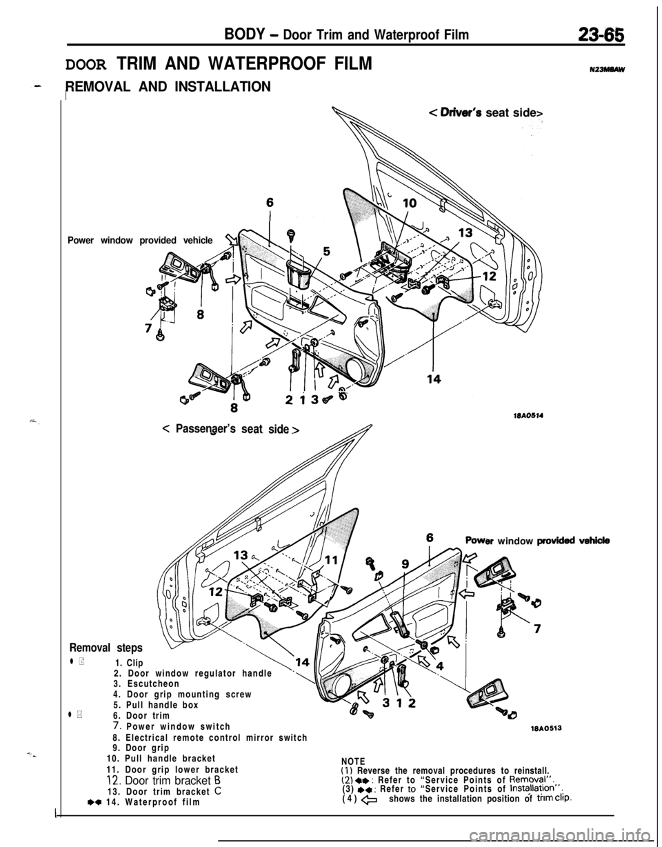
DOOR TRIM AND WATERPROOF FILM
REMOVAL AND INSTALLATIONI
Power window provided vehicle%l \PL
< Oriver’s seat side>
2i36~4
15AO514<
Passenaer’s
seat
side >
er window provkkd
Removal steps2. Door window regulator handle
3. Escutcheon
4. Door grip mounting screw
5. Pull handle box
l *6. Door trim
l +1. Clip
7. Power window switchWA05138. Electrical remote control mirror switch
9. Door grip
10. Pull handle bracket
11. Door grip lower bracketNOTE
(1) Reverse the removal procedures to reinstall.12. Door trim bracket B(2) a* : Refer to “Service Points of Removal”.13. Door trim bracket
C(3) +* : Refer to “Service Points of Installa~lon”,
*c 14. Waterproof film(4) +shows the installation position of trim Clip.
I
Page 1116 of 1216
23-72BODY -Door Moulding and Drip Line Weatherstrip/Door Mirror
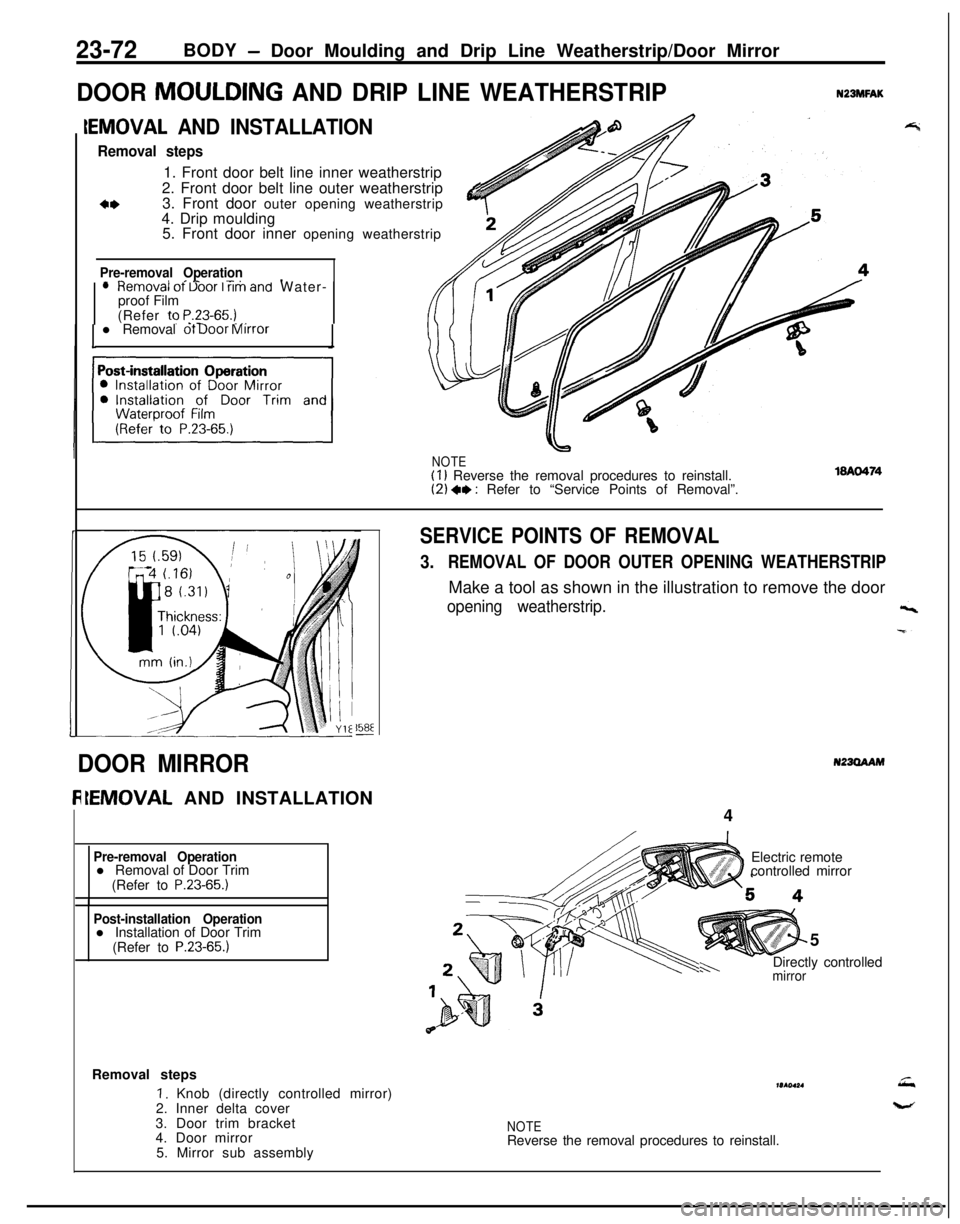
DOOR MOULDING AND DRIP LINE WEATHERSTRIPNZBMFAK
IEMOVAL AND INSTALLATION
Removal steps1. Front door belt line inner weatherstrip
2. Front door belt line outer weatherstrip
3. Front door outer opening weatherstrip
&4. Drip moulding
5. Front door inner opening weatherstrip
Pre-removal Operation- ^II_ -..lHemOVal ot Uoor I rim and Water-
proof Film
(Refer to
P.23-65.) _,. -l Removal ot Door Mirror
NOTE(I 1 Reverse the removal procedures to reinstall.(2) +, : Refer to “Service Points of Removal”.
158E-
SERVICE POINTS OF REMOVAL
3.REMOVAL OF DOOR OUTER OPENING WEATHERSTRIPMake a tool as shown in the illustration to remove the door
opening weatherstrip.
N23OAAMDOOR MIRROR
IEMOVAL AND INSTALLATION
4
Pre-removal Operationl Removal of Door Trim
(Refer to
P.23-65.)
Post-installation Operationl Installation of Door Trim
(Refer to
P.23-65.)5
mirrorh-.Directly controlled Electric remote
controlled mirror
Removal steps
I. Knob (directly controlled mirror)
2. Inner delta cover
3. Door trim bracket
4. Door mirror
5. Mirror sub assemblymr(ol*.
NOTEReverse the removal procedures to reinstall.
Page 1117 of 1216
BODY - Door Mirror/Electric Remote Controlled Mirror Switch23-73
18AO425
16P0109-
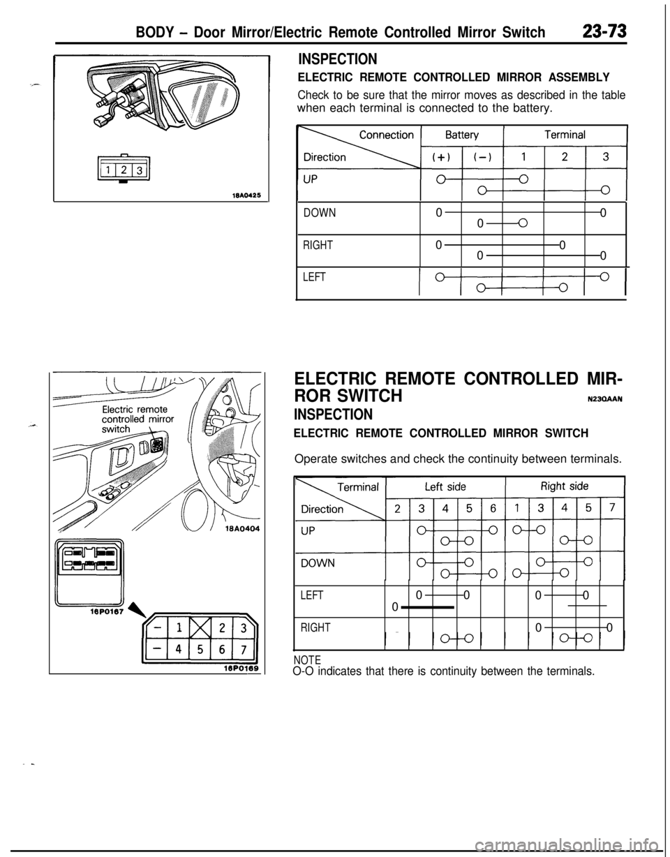
INSPECTION
ELECTRIC REMOTE CONTROLLED MIRROR ASSEMBLY
Check to be sure that the mirror moves as described in the tablewhen each terminal is connected to the battery.
DOWN0
0
00
RIGHT0
0
0
0
LEFT
IOI
ELECTRIC REMOTE CONTROLLED MIR-
ROR SWITCH
N23QAAN
INSPECTION
ELECTRIC REMOTE CONTROLLED MIRROR SWITCHOperate switches and check the continuity between terminals.
LEFT00
00
0
RIGHT00
NOTEO-O indicates that there is continuity between the terminals.
..
Page 1156 of 1216

24-12 HEATERS AND AIR CONDITIONING - Service Adjustment Procedures
------__--210 2352,100 Pressure
(30) (33)(299) 2&
kPa(psi)2OPOO14(3) If the sight glass is clear and the magnetic clutch is
disengaged; the clutch is faulty or, the system is out of
refrigerant. Perform low pressure switch test to determine
condition. Check low pressure switch, and clutch coil for
electrical continuity.
(4) If the sight glass shows foam or bubbles, the system could
be low on charge. Occasional foam or bubbles are normal
when the ambient temperature is above
43°C (110°F) or
below
21°C (70°F).Adjust the engine speed to 1,500 rpm. Block the air-flow
thru the condenser to increase the compressor discharge
pressure to 1,422 to 1,520
kPa (206 to 220 psi). If sight
glass still shows bubbles or foam, system charge level is
low.The refrigerant system will not be low on charge unless
there is a leak. Find and repair the leak. If the leak can be
repaired without discharging the system an oil level check
is not necessary. Use the procedure for correcting low
refrigerant level found in the Refrigerant System Service
Procedure Section.DUAL PRESSURE SWITCH
The dual-pressure switch is a combination of the low-pressureswitch (for checking the quantity of refrigerant) and the,
high-pressure switch (for prevention of overheating); it is
installed on the tube, and, when the pressure becomes
approximately 210 kPa (30 psi) or lower, the compressor stops,thus preventing the compressor from being damaged by heat.
When the pressure reaches 2,700
kPa (384 psi) or higher, the
compressor stops, thus preventing overheating. There is
generally no necessity for inspection; if, however, an unusual
condition, such as non-operation of the compressor is encoun-tered, check by following the procedures below.
(1) Check for continuity of the dual-pressure switch.
NOTEIf the air temperature drops to
0°C (32°F) or lower during
cold weather, the air conditioner will not operate (no
continuity).(2) If there is an insufficient amount of refrigerant, check the
refrigerant amount by looking through the sight glass of thereceiver; supply refrigerant if necessary.
(Refer to P.24-21.)
Page 1159 of 1216
HEATERS AND AIR CONDITIONING - Service Adjustment Procedures 24-15
Liquid
line
\Liquid lineI
ILiquid lineHigh pressure
hose2010439
detector torch
Electric leakAdetector tester
2OUO338
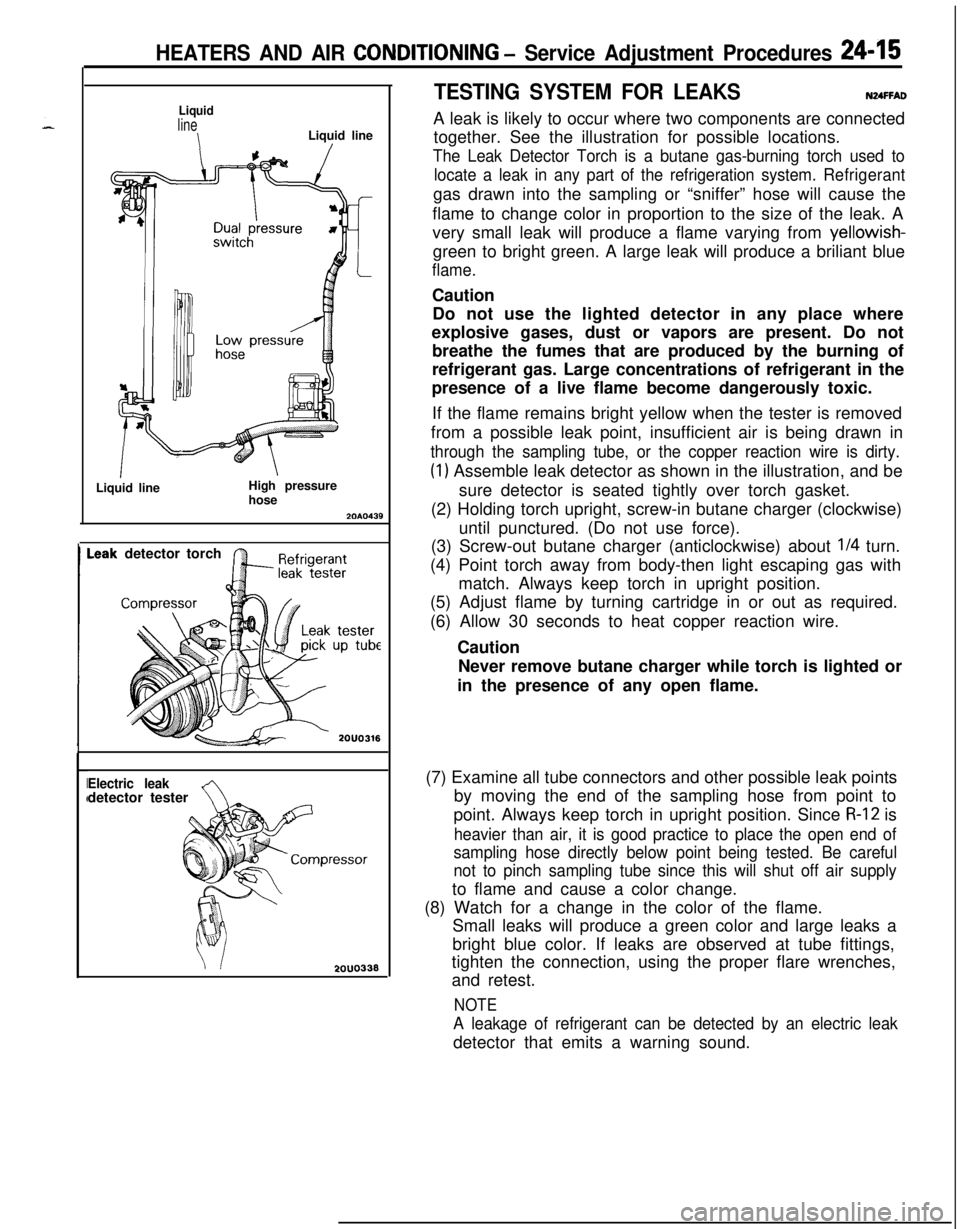
TESTING SYSTEM FOR LEAKSNUFFADA leak is likely to occur where two components are connected
together. See the illustration for possible locations.
The Leak Detector Torch is a butane gas-burning torch used to
locate a leak in any part of the refrigeration system.Refrigerantgas drawn into the sampling or “sniffer” hose will cause the
flame to change color in proportion to the size of the leak. A
very small leak will produce a flame varying from yellowish-
green to bright green. A large leak will produce a briliant blue
flame.Caution
Do not use the lighted detector in any place where
explosive gases, dust or vapors are present. Do not
breathe the fumes that are produced by the burning of
refrigerant gas. Large concentrations of refrigerant in the
presence of a live flame become dangerously toxic.
If the flame remains bright yellow when the tester is removed
from a possible leak point, insufficient air is being drawn in
through the sampling tube, or the copper reaction wire is dirty.
(1) Assemble leak detector as shown in the illustration, and be
sure detector is seated tightly over torch gasket.
(2) Holding torch upright, screw-in butane charger (clockwise)
until punctured. (Do not use force).
(3) Screw-out butane charger (anticlockwise) about
l/4 turn.
(4) Point torch away from body-then light escaping gas with
match. Always keep torch in upright position.
(5) Adjust flame by turning cartridge in or out as required.
(6) Allow 30 seconds to heat copper reaction wire.
Caution
Never remove butane charger while torch is lighted or
in the presence of any open flame.
(7) Examine all tube connectors and other possible leak points
by moving the end of the sampling hose from point to
point. Always keep torch in upright position. Since
R-12 is
heavier than air, it is good practice to place the open end of
sampling hose directly below point being tested. Be careful
not to pinch sampling tube since this will shut off air supplyto flame and cause a color change.
(8) Watch for a change in the color of the flame.
Small leaks will produce a green color and large leaks a
bright blue color. If leaks are observed at tube fittings,
tighten the connection, using the proper flare wrenches,
and retest.
NOTE
A leakage of refrigerant can be detected by an electric leakdetector that emits a warning sound.