1991 MITSUBISHI ECLIPSE electric
[x] Cancel search: electricPage 495 of 1216

FUEL SYSTEM - Service Adjustment Procedures <1.8L Engine>l-4-41
SERVICE ADJUSTMENT PROCEDURES
CURB IDLE SPEED INSPECTION
CautionNlIFiiAE
The improper setting (throttle valve opening) will increase
exhaust gas temperature at deceleration, reducing catalystlife greatly and deteriorating exhaust gas cleaning per-
formance. It also has effect on fuel consumption and
engine braking.
ilter
Paper clip
16A0898
PI-e-conditions for inspection
0Engine coolant temperature: 85-95°C (185-205°F)
0Lights, electric cooling fan and accessories: OFF
l Transaxle: Neutral
(P for vehicles with an automatic
transaxle)l Steering wheel: Neutral position (vehicles with a power
steering)l Check ignition timing and adjust if necessary. Refer to
GROUP 8.
NOTEWith vehicles for Canada, the headlights and taillights, etc.
remain on even when the lighting switch is turned OFF, but thiscauses no problems during inspection.
(1) Insert the paper clip to the connector.
(2) Connect the tachometer to the inserted clip.
(3)Run the engine for more than 5 seconds at an engine speedof 2,000 to 3,000 rpm.
(4) Run the engine at idle for 2 minutes.
(5) Read the idling rpm. If it is not within the specified speed,
check the idle speed control system.
Curb idle speed: 700
f 100 rpm
NOTEAdjustment of the idling speed is usually unnecessary,
because this system controls the idling speed.
IDLE SPEED CONTROL AND
THROTlLE POSI-
TION SENSOR ADJUSTMENT
N14FIATAdjustment conditions
l Engine coolant temperature:
85-95X (185-205°F)
l Lights, electric cooling fan and accessories: Set to OFF
l Transaxle: Neutral (P for vehicles with an automatic
transaxle)l Steering wheel: Neutral position (vehicles with a power
steering)
(1) Slacken the accelerator cable enough.
(2) Connect a tachometer.
Page 502 of 1216

14-48FUEL SYSTEM - Service Adjustment Procedures <2.0L Engine>
SERVICE ADJUSTMENT PROCEDURES
<2.0L DOHC Engine>
CURB IDLE SPEED INSPECTION
Caution
N14FHADThe improper setting (throttle valve opening) will increase
exhaust gas temperature at deceleration, reducing
catalys-tic converter life greatly and deteriorating exhaust gas
cleaning performance. It also has effect on fuel ‘consump-
tion and engine braking.
Pre-conditions for inspection
l Engine coolant temperature:
85-95°C (185-205°F)
l Lights, electric cooling fan and accessories: OFF
lTransaxle: Neutral (P for vehicles with automatic transaxle)l Steering wheel: Neutral position (vehicles with a power-
steering)l Check ignition timing and adjust if necessary. Refer to
GROUP 8.
NOTEWith vehicles for Canada, the headlights and taillights, etc.
remain on even when the lighting switch is turned OFF, but thiscauses no problems during inspection.
(1) Connect the tachometer to the engine speed detection
terminal.
(2)Run the engine for more than 5 seconds at an engine speedof 2,000 to 3,000 rpm.
(3) Run the engine at idle for 2 minutes.
(4) Read the idling rpm. If it is not within the specified speed,
check the idle speed control system.
Curb idle speed:
750f 100 rpm
NOTE1. Adjustment of the idling speed is usually unnecessary,
because this system controls the idling speed.
2.For rpm, one-half of the actual engine rpm is indicated,so the actual engine rpm is two times the indicated
value shown by the tachometer.
BASIC IDLE SPEED ADJUSTMENT
N14FHBIPre-conditions for inspection
l Engine coolant temperature:
85-95°C (185-205°F)
l Lights, electric cooling fan, and accessories: OFF
lTransaxle: Neutral (P for vehicles with automatic transaxle)l Steerig wheel: Neutral position (vehicles with a
power-
steering)(1) Connect a tachometer.
Page 547 of 1216

FUEL SYSTEM - Fuel Tank
FUEL TANK cFWD>
,*. REMOVAL AND INSTALLATION
q?&g
NlMA-30-40 Nm
2-3 Nm22-29 ft.lbs.
---15-20 Nm
11-14 ft.lbs.
15-22 ft.lbs.Removal steps
l + 1. Return hosel +2. Vapor hose
3. Clamp
4. Fuel gauge unit connector
5. Electrical fuel pump connector
l + l q6. High pressure fuel hose
l + 7. Filler hose
l + 8. Vapor hose
~~ 9. Self-locking nut10. Tank band11. Fuel tank
l + 12. Vapor hosel + 13. Overfill limiter (Two-way valve)I)+ 14. Fuel gauge unitl + 15. Electrical fuel pump16. Drain plug
17. Fuel tank cap
18. Packing
19. Fuel filler neck$TEeverse the removal procedures to reinstall,(2) +e : Refer to “Service Points of Removal”:,,
(3) *+ : Refer to “Service Points of lnstallatlon .(4) m : Non-reusable parts
Page 548 of 1216
14-94FUEL SYSTEM - Fuel Tank
Outlet side_ Inlet side01
W838
Positioning projection
03A0220SERVICE POINTS OF REMOVALtilirro8AH
6. DISCONNECTION OF HIGH PRESSURE FUEL
H;OSECaution
Cover the hose connection with rags to prevent splash
of fuel that could be caused by some residual pressure
in the fuel pipe line.
INSPECTIONN14GCAll Check the hoses and the pipes for crack or damage.
l Check the fuel tank cap for malfunction.
l Check the fuel tank for deformation, corrosion or crack.
0,. Check the fuel tank for dust or foreign material.
NOTE
If the inside of the fuel tank is to be cleaned, use any one ofthe following:
(1) Kerosene
(2)
Trichloroethylene-(3) A neutral emulsion type detergent
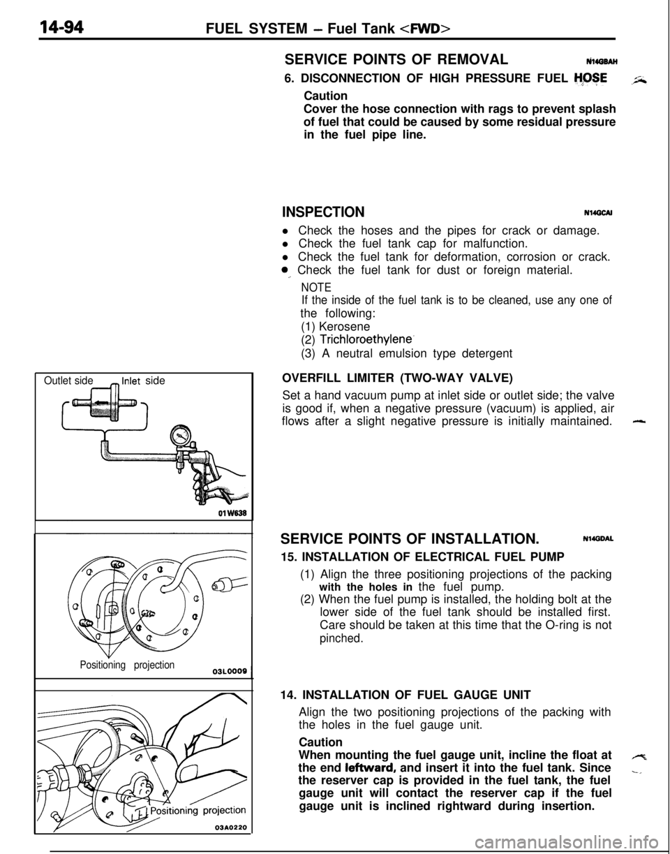
OVERFILL LIMITER (TWO-WAY VALVE)
Set a hand vacuum pump at inlet side or outlet side; the valve
is good if, when a negative pressure (vacuum) is applied, air
flows after a slight negative pressure is initially maintained.
SERVICE POINTS OF INSTALLATION.
Nl4DDAL15. INSTALLATION OF ELECTRICAL FUEL PUMP
(1) Align the three positioning projections of the packing
with the holes in the fuel pump.
(2) When the fuel pump is installed, the holding bolt at the
lower side of the fuel tank should be installed first.
Care should be taken at this time that the O-ring is not
pinched.14. INSTALLATION OF FUEL GAUGE UNIT
Align the two positioning projections of the packing with
the holes in the fuel gauge unit.
Caution
When mounting the fuel gauge unit, incline the float at
the end leftward, and insert it into the fuel tank. Since
the reserver cap is provided in the fuel tank, the fuel
gauge unit will contact the reserver cap if the fuel
gauge unit is inclined rightward during insertion.
-
4
-,
Page 553 of 1216
FUEL SYSTEM -Fuel Pump, Fuel Gauge Unit and Overfill Limiter (Two-Way Valve)
FUEL PUMP, FUEL GAUGE UNIT AND OVERFILL LIMITER (TWO-WAY
J-.VALVE)
NWJA-Pre-removal Operation
eDraining of the Fuel
Post-installation Operation
l supplying of the Fuel1.4-2.2
ft.lbs.
/ 1.4-2.2ft.lbs.
21-31 Nm
80-100 Nm+
6.5- 10ftlbs.
13AO333
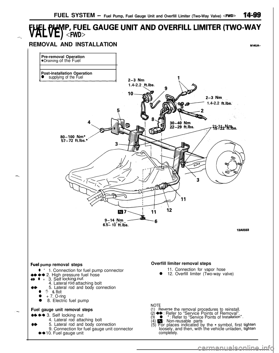
Qel pump removal steps
l *1. Connection for fuel pump connector
C+ ~~ 2. High pressure fuel hoseC+ l +3. Self lockingnut
4. Lateral Pod attaching bolt
a*5. Lateral rod and body connectionl I 6. Boltl + 7. O-ringl 8. Electric fuel pump
Fuel gauge unit removal steps
W e+ 3. Self locking nut
4. Lateral rod attaching bolt
c*5. Lateral rod and body connection9. Connection for fuel gauge unit connector
I)+ 10. Fuel gauge unitOverfill limiter removal steps
11. Connection for vapor hosel 12. Overfill limiter (Two-way valve)
FF:everse the removal procedures to reinstall.(2) +e : Refer to “Service Points of Removal”.(3) l * : Refer to “Service Points of Installation”.(4) m : Non-reusable parts(5) For places indicated by the * symbol, first tightenloosely, and then, with the vehicle unladen, tighten
completely.
Page 554 of 1216
14-100 FUEL SYSTEM- Fuel Pump, Fuel Gauge Unit and Overfill Limiter (Two-Way Valve) 4WD>SERVICE POINTS OF REMOVAL
NI4tmM2. DISCONNECTION OF HIGH PRESSURE FUEL HOSE
Refer to
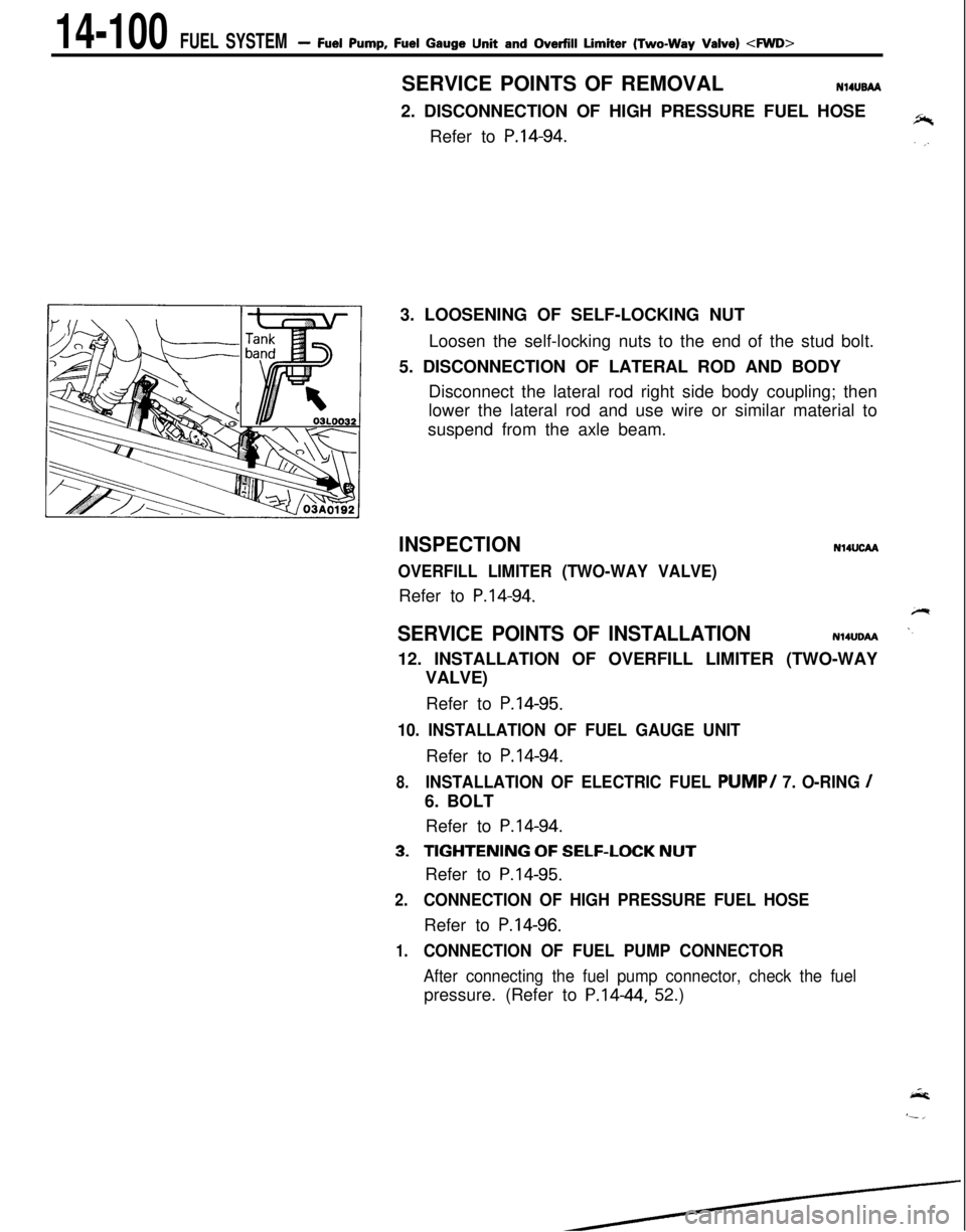
P.14-94.3. LOOSENING OF SELF-LOCKING NUT
Loosen the self-locking nuts to the end of the stud bolt.
5. DISCONNECTION OF LATERAL ROD AND BODY
Disconnect the lateral rod right side body coupling; then
lower the lateral rod and use wire or similar material to
suspend from the axle beam.
INSPECTION
OVERFILL LIMITER (TWO-WAY VALVE)Refer to
P.14-94.
N14UcM
SERVICE POINTS OF INSTALLATIONN14UDAA12. INSTALLATION OF OVERFILL LIMITER (TWO-WAY
VALVE)
Refer to
P.14-95.
10. INSTALLATION OF FUEL GAUGE UNITRefer to
P.14-94.
8.INSTALLATION OF ELECTRIC FUEL PUMP/ 7. O-RING /6. BOLT
Refer to
P.14-94.
3.TIGHTENING OF SELF-LOCK NUTRefer to
P.14-95.
2.CONNECTION OF HIGH PRESSURE FUEL HOSERefer to
P.14-96.
1.CONNECTION OF FUEL PUMP CONNECTOR
After connecting the fuel pump connector, check the fuelpressure. (Refer to P.1444, 52.)
Page 1045 of 1216
23-lBODY
CONTENTSN23Ak-
AERO PARTS..........................................74
CENTRAL DOOR LOCKING SYSTEM...........70
DOOR ASSEMBLY....................................63
DOOR GLASS AND REGULATOR................66
DOORHANDLEANDLATCH.....................69
DOOR MIRROR........................................72
DOOR MOULDING AND
DRIP LINE WEATHERSTRIP........................72
....DOOR RUNCHANNEL...............................71
DOOR TRIM AND WATERPROOF FILM........65
ELECTRIC REMOTE CONTROLLED
MIRROR SWITCH.....................................73
FENDER..................................................51
FLOOR CONSOLE....................................84
FRONT BUMPER......................................39
FRONT SEAT..........................................90
FUEL TANKFILLERDOOR.........................38
GARNISHES............................................47
HEADLINING...........................................89
HOOD....................................................34
INSTRUMENT PANEL................................79
LIFTGATE...............................................36
LIFTGATE WINDOWGLASS......................62
LOOSE PANEL.........................................53
MOULDING.............................................48
POWER WINDOW....................................67
QUARTERWINDOWGLASS......................61
REAR BUMPER........................................43
REAR SEAT............................................93
SEAT BELT.............................................94
SERVICE ADJUSTMENT PROCEDURES........31
Door Adjustment....................................32
Door Glass Adjustment............................32Door Inside Handle Play Check..................
32
Door Outside Handle Play Check................32
Floor PanInspection...............................
33Fuel Filler Door Adjustment.......................
31
Hood Adjustment...................................31
Liftgate Adjustment.................................31
Water Test...........................................33
SPECIAL TOOLS......................................5
SPECIFICATIONS.....................................2
General Specifications..............................
2
Lubricants.............................................5
Sealants and Adhesives...........................5
Service Specifications..............................3
Torque Specifications..............................3
SUNROOF...............................................77TRIMS
....................................................85
TROUBLESHOOTING................................6WINDOW
GLASS.....................................54
WINDSHIELD...........................................58
Page 1054 of 1216
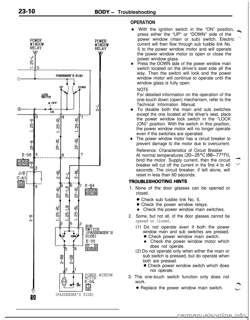
23-10BODY - Troubleshooting
(PABBENGER’B BIDE)v 1
E-51
‘S
E-05
I2
m3458
POWER WINDOW
MOTOR
E-04
OPERATIONl With the ignition switch in the “ON” position,
rs;,press either the “UP” or “DOWN” side of the
power window (main or sub) switch. Electric
-*
current will then flow through sub fusible link No.5 to the power window motor and will operate
the power window motor to open or close the
power window glass.
lPress the DOWN side of the power window mainswitch located on the driver’s seat side all the
way. Then the switch will lock and the power
window motor will continue to operate until the
window glass is fully open.
NOTEFor detailed information on the operation of the
one-touch down (open) mechanism, refer to the
Technical Information Manual.l To disable both the main and sub switches
except the one located at the driver’s seat, placethe power window lock switch in the “LOCK
(ON)” position. With the switch in this position,
the power window motor will no longer operate
even if the switches are operated.
lThe power window motor has a circuit breaker to
prevent damage to the motor due to overcurrent.
Reference: Characteristics of Circuit BreakerAt normal temperatures
[ZO-25OC (68-77”F)I,bind the motor. Supply current, then the circuit
h
breaker will cut off the current in the first 4 to 40\&’seconds. The circuit breaker, if left alone, will
reset in less than 60 seconds.
TROUBLESHOOTING HINTS1. None of the door glasses can be opened or
closed.0 Check sub fusible link No. 5.0 Check the power window relays.
l Check the power window main switches.
2.Some, but not all, of the door glasses cannot be
opened or closed.
(I) Do not operate even if both the power
window main and sub switches are pressed.0 Check power window main switch.
l Check the power window motor which
does not operate.
(2) Do not operate only when either the main or
sub switch is pressed, but do operate when
both are pressed.0 Check power window switch which does
not operate.3. The one-touch switch function only does not
work.A0 Replace the power window main switch.
w
(PASSENGER'S SIDE)