Page 1109 of 1216
BODY - Door Trim and Waterproof Film2345
DOOR TRIM AND WATERPROOF FILM
REMOVAL AND INSTALLATIONI
Power window provided vehicle%l \PL
< Oriver’s seat side>
2i36~4
15AO514<
Passenaer’s
seat
side >
er window provkkd
Removal steps2. Door window regulator handle
3. Escutcheon
4. Door grip mounting screw
5. Pull handle box
l *6. Door trim
l +1. Clip
7. Power window switchWA05138. Electrical remote control mirror switch
9. Door grip
10. Pull handle bracket
11. Door grip lower bracketNOTE
(1) Reverse the removal procedures to reinstall.12. Door trim bracket B(2) a* : Refer to “Service Points of Removal”.13. Door trim bracket
C(3) +* : Refer to “Service Points of Installa~lon”,
*c 14. Waterproof film(4) +shows the installation position of trim Clip.
I
Page 1110 of 1216

23-66BODY - Door Trim and Waterproof Film/Door Glass and Regulator
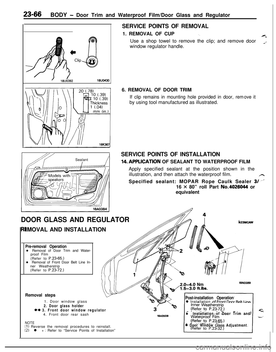
SERVICE POINTS OF REMOVAL1. REMOVAL OF CUP
‘.+iUse a shop towel to remove the clip; and remove door
_Awindow regulator handle.
IbY ISealant!I6. REMOVAL OF DOOR TRIM
If clip remains in mounting hole provided in door, remby using tool manufactured as illustrated.ove it
SERVICE POINTS OF INSTALLATION14,APPLlCATlON OF SEALANT TO WATERPROOF FILM
Apply specified sealant at the position shown in the
illustration, and then attach the waterproof film.
/rSpecified sealant: MOPAR Rope Caulk Sealer
3/ --‘I16
X 80” roll Part No.4026044 or
equivalent
DOOR GLASS AND REGULATORIMOVAL AND INSTALLATION
Pre-removal Operationl Removal of Door Trim and Water-
proof Film
(Refer to P.23-65.)
l Removal of Front Door Belt Line In-
ner Weatherstrip
(Refer to P.23-72.)
N23MCAW2.0-4-O
Nm1.5-3.0 ft.lbs.
Removal steps1. Door window glass
2. Door glass holder
*4 3. Front door window regulator
4. Front door rear sash
NOTEII ) Reverse the removal procedures to reinstall.12) l + : Refer to “Service Points of Installation”
Post-installation Operation0 Installation nf Frnnt lhnr Rnlt I inn
l Installation of Door Trim and
0 Door Window Glass Adjustment
Page 1111 of 1216
BODY - Door Glass and Reaulator/Power Window23-67
POWER WINDOW
REMOVAL AND INSTALLATIONSERVICE POINTS OF INSTALLATION3. APPLICATION OF GREASE TO FRONT DOOR WINDOW
REGULATORApply multipurpose grease to all moving parts.
Grease: MOPAR Multipurpose Grease Part No.
2932524 or equivalent
N23MHAEa
71l Door Window Glass Adjustment
< Passenger’s seat side >NOTE
(1) Reverse the removal procedures to reinstall.(2) l + : Refer to “Service Points of Installation”.
1810469Power window relay removal
1. Power window relay
Power window switch removal steps
Door trim (Refer to P.23-65.)2. Power window main switch
3. Power window sub switch
Power window motor removal steps
Door trim and waterproof film
(Refer to
P.23-65.)4. Door window glass
l + 5. Front door window regulator
16l.03443 416AO606
INSPECTIONPOWER WINDOW RELAY
Apply battery voltage to terminal 2, and check for continuity
when terminal 4 is grounded.
NOTEO-O indicates that there is continuity between the terminals.
Page 1112 of 1216
23-68BODY - Power Window
Power
window
lock
switch
,POWER WINDOW MOTOR
(1) Connect the motor terminal directly to the battery and
check to be sure that the slider moves smoothly.
(2) Also check to be sure that the slider moves in the opposite
direction when the battery polarity connections are
changed.CIRCUIT BREAKER (INCORPORATED IN THE POWER
WINDOW
MOTOR)
(1) Press the UP switch to fully close the window glass, and
continue to press the switch for
10 seconds.
(2) At the moment that the UP switch is released, press the
DOWN switch. The circuit breaker can be considered goodif at this time the door window glass begins to open within
60 seconds.POWER WINDOW MAIN SWITCH
Check for continuity in accordance to the following connection
table.
NOTEO-O indicates that there is continuity between the terminals.
Page 1113 of 1216

BODY - Power Window/Door Handle and Latch23-69
I-
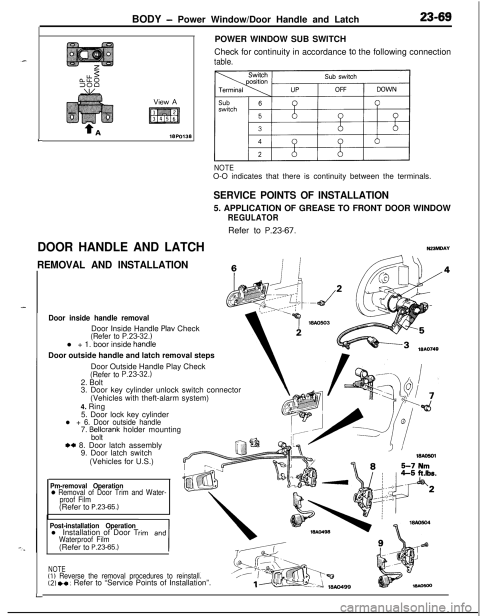
DOOR HANDLE AND LATCHPOWER WINDOW SUB SWITCH
Check for continuity in accordance
10 the following connection
table.
NOTEO-O indicates that there is continuity between the terminals.
SERVICE POINTS OF INSTALLATION5. APPLICATION OF GREASE TO FRONT DOOR WINDOW
REGULATORRefer to
P.23-67.
N23MDAY
REMOVAL AND INSTALLATIONc
Door inside handle removalDoor Inside Handle
Plav Check(Refer to P.23-32.1l + 1. boor inside
handieDoor outside handle and latch removal steps
LDoor Outside Handle Play Check
(Refer to P.23-32.)2. Bolt
3. Door key cylinder unlock switch connector
(Vehicles with theft-alarm system)
4. Ring
5. Door lock key cylinder
l + 6. Door outside handle7. Bellcrank holder mountingbolt
.a 8. Door latch assembly
9. Door latch switch
(Vehicles for U.S.)
Pm-removal Operation0 Removal of Door Trim and Water-
proof Film(Refer to
P.23-65.)
Post-installation Operationl Installation of Door Trim and
1
Waterproof Film(Refer to P.23-65.)
NOTE(I)
Reverse the removal procedures to reinstall.‘/(2) *+ : Refer to “Service Points of Installation”.1m
Page 1115 of 1216

BODY - Central Door Locking System/Door Runchannel23-71View A
18A0064-
L
DOOR RUNCHANNEL
REMOVAL AND INSTALLATION
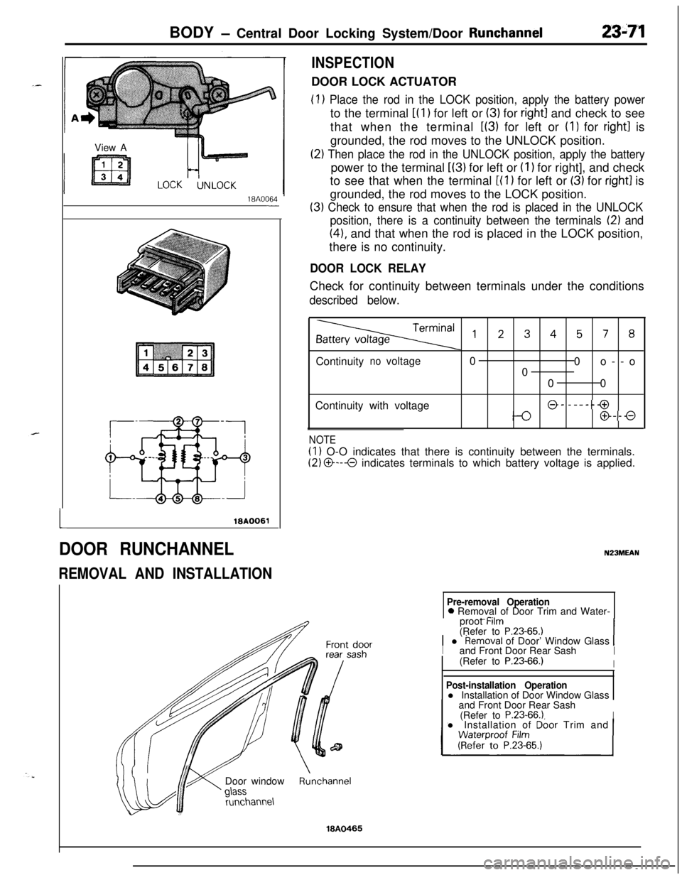
INSPECTIONDOOR LOCK ACTUATOR
(1) Place the rod in the LOCK position, apply the battery powerto the terminal
i(l) for left or (3) for right1 and check to see
that when the terminal
L(3) for left or (I) for right1 is
grounded, the rod moves to the UNLOCK position.
(2) Then place the rod in the UNLOCK position, apply the batterypower to the terminal
L(3) for left or (I 1 for right], and check
to see that when the terminal
[(l ) for left or (3) for right1 is
grounded, the rod moves to the LOCK position.
(3) Check to ensure that when the rod is placed in the UNLOCK
position, there is a continuity between the terminals
12) and
(41, and that when the rod is placed in the LOCK position,
there is no continuity.
DOOR LOCK RELAYCheck for continuity between terminals under the conditions
described below.
,2345, 8Continuity
novoltage0
0o--o
0
00
Continuity with voltage
@- -----@
@--0
NOTE
(1) O-O indicates that there is continuity between the terminals.
(2) O---O indicates terminals to which battery voltage is applied.
N23MEAN
Pre-removal Operation0 Removal of Door Trim and Water-
_ -..proot Mm
(Refer to
P.23-65.11 l Removal of Door’ Window Glass 1Iand Front Door Rear SashI(Refer to P.23-66.)IDoor window
runchannel
Post-installation Operationl Installation of Door Window Glass
and Front Door Rear Sash
(Refer to
P.23-66.1Il Installation of Dbor Trim and
Runchannel
18A0465
Page 1126 of 1216
23-82BODY - Instrument Panel
9N23
Cluster panel (A) disassembly steps
1. Switch holder (A)2. Headlight pop-up switch
3. Plug
(A)4. Rheostat
5. Cluster panel
(A)
Cluster panel (B) disassembly steps6. Switch holder
(5)7. Hazard switch
8.
p;Fr window defogger switch or plug
9.
$far wiper and washer switch or plug10. Heater control panel assembly
II. Cluster panel (B)
Knee protector disassembly steps12. Lap cooler grill assembly
13. Knee protector
Glove box disassembly steps14. Glove box lock assembly
15. Glove box pad
16. Glove box hinge
17. Glove box
Instrument panel disassembly steps18. Glove box light switch
19. Lower frame
20. Corner pad21. Glove box striker
22. Glove box light bracket
23. Speakers
Page 1160 of 1216

24-16 HEATERS AND AIR CONDITIONING - Service Adjustment Procedures
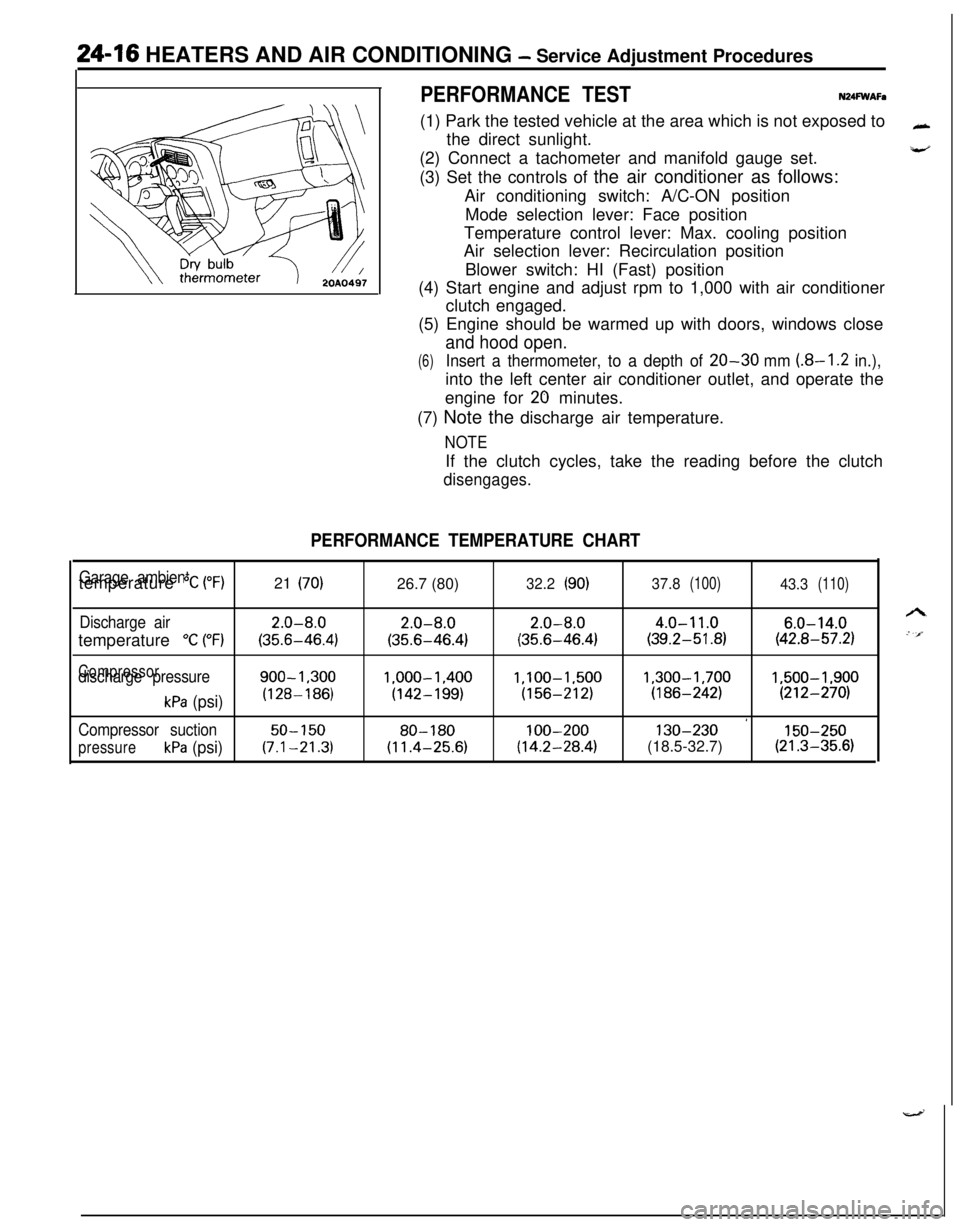
PERFORMANCE TESTN24FWAFa(1) Park the tested vehicle at the area which is not exposed to
the direct sunlight.
(2) Connect a tachometer and manifold gauge set.
(3) Set the controls of the air conditioner as follows:
Air conditioning switch: A/C-ON position
Mode selection lever: Face position
Temperature control lever: Max. cooling position
Air selection lever: Recirculation position
Blower switch: HI (Fast) position
(4) Start engine and adjust rpm to 1,000 with air conditioner
clutch engaged.
(5) Engine should be warmed up with doors, windows close
and hood open.
(6)Insert a thermometer, to a depth of 20-30 mm (8-I .2 in.),into the left center air conditioner outlet, and operate the
engine for
20 minutes.
(7) Note the discharge air temperature.
NOTEIf the clutch cycles, take the reading before the clutch
disengages.
PERFORMANCE TEMPERATURE CHART
Garage ambienttemperature “C (“F)21 (70)26.7 (80)32.2(90)37.8(100)43.3(110)
Discharge air2.0-8.02.0-8.02.0-8.04.0-11.06.0-14.0temperature
“C (“F)(35.6-46.4)(35.6-46.4)(35.6-46.4)(39.2-51.8)(42.8-57.2)
Compressordischarge pressure900-1.3001.000-1.400l,lOO-1,5001,300-1,7001,500-1,900
kPa (psi)(128-186)(142-199)(156-212)(186-242)(212-270)
’Compressor suction50-15080-180100-200130-230150-250
pressurekPa (psi)(7.1-21.3)(11.4-25.6)(14.2-28.4)(18.5-32.7)(21.3-35.6)