Page 1018 of 1216
21-324AUTOMATIC TRANSAXLE - Valve Body
VALVE BODY
DISASSEMBLY AND REASSEMBLYViewed from A
NZlLOAK
-0 - -
8
TFA0523
Disassembly steps
1. Manual valve
l +2. Pressure control solenoid valvel +3. Damper clutch control solenoid v
l +4. Shift control solenoid valve “A”
l +5. Shift control solenoid valve “B”6. Clamp
7. Valve stopper
8. N-D control sleeve
9. N-D control valve
l + 10. Lower valve body sub assembly11. Lower separating plate12.Nut13.Jet
l + 14. Relief spring
l + 15. Steel ballH 16. Oil filterW 17. Upper valve body sub assemblyWI
18. Steel ball
H 19. Teflon balll 420.N-Delate
NOTE(1) Reverse the disassembly procedures to reassemble.(2) l 4 : Refer to “Service Points of Reassembly”.
21. Block22. Upper separating plate
23. Intermediate plate
Page 1019 of 1216
AUTOMATIC TRANSAXLE - Valve Bodv2646
38
I24
24. Fornt end cover
25. Pressure control spring
26. Pressure control valve
27. Torque converter control spring
28. Torque converter control valve
29. Adjusting screw
30. Regulator spring
31. Regulator valve32. Shift controlspring++ 33. Stopper plate
34. Shift control plug
35. Rear clutch exhaust valve A36. Rear clutch exhaust valve B37. Rear clutch exhaust springViewed from
B
.
I40
TFA0518
38.2-314-3shiftspring39.2-3/4-3shiftvalve40. Rear end cover41. Shift control plug Bl + 42. Stopper plate43. Shift control valve
44. l-2 shift spring
45.
l-2 shift valve
46. Upper valve body
NOTE(1) Reverse the disassembly procedures to reassemble.(2) I)4 : Refer to “Service Points of Reassembly”.
Page 1020 of 1216
21-326AUTOMATIC TRANSAXLE - Valve Body
TFAOS22
47. Pin
48. Stopper
49. End clutch plug
50. End clutch spring
51. End clutch valve
52. End cover53. Plug
58. N-R control spring59. Adjusting screw
60. Reducing spring
61. Reducing valve62. Lower valve body
54. Damper clutch control sleeve
55. Damper clutch control valve
56. Damper clutch control spring 57. N-R control valve
NOTE(1) Reverse the disassembly procedures to reassemble.(2) l 4 : Refer to “Service Points of Reassembly”.
Page 1022 of 1216
21-328AUTOMATIC TRANSAXLE - Valve Bodv
XSV-ASkV-Brj,,SV (FJA22)TFAM80(3) After securing the lower valve body by
the installationbolt, remove the special tool.
Sk
5./4./3./2. INSTALLATION OF SOLENOID VALVE ASSEM-
BLYInstall each solenoid valve in the position shown in the
figure.
Solenoid valveWiring colorI
Shift control solenoid valve “A”
Shift control solenoid valve “B”
Damper clutch control solenoid valve
Yellow
Red
Pressure control solenoid valveBlue
Page 1146 of 1216

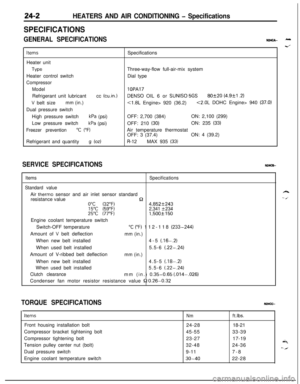
24-2HEATERS AND AIR CONDITIONING - Specifications
SPECIFICATIONS
GENERAL SPECIFICATIONSN24cA- -
ItemsSpecifications
Heater unit
TypeThree-way-flow full-air-mix system
Heater control switchDial type
Compressor
Model
lOPARefrigerant unit lubricantcc
(cu.in.1DENS0 OIL 6 or SUNISO 5GS80f20 (4.9&l .2)
V belt sizemm (in.)<1.8L Engine> 920 (36.2)<2.0L DOHC Engine> 940 (37.0)Dual pressure switch
High pressure switch
kPa (psi)OFF: 2,700 (384)ON: 2,100 (299)
Low pressure switch
kPa (psi)OFF: 210 (30)ON: 235 (33)
Freezer prevention“C (“F)Air temperature thermostat
OFF: 3 (37.4)ON: 4 (39.2)
Refrigerant and quantity
g bdR-12MAX 935 (33)
SERVICE SPECIFICATIONSN24CB.-
ItemsSpecifications
Standard valueAir
therm0 sensor and air inlet sensor standard
resistance value
n0°C (32°F)4,852f24315°C (59°F)2,341 f23425°C 177°F)1,500f 150Engine coolant temperature switch
Switch-OFF temperature
“C (“F) 112-118 (233-244)
Amount of
V belt deflection
mm (in.)
When new belt installed4-5
(.16-.2)When used belt installed5.5-6
(.22-.24)Amount of V-ribbed belt deflection
mm (in.)
When new belt installed4.5-5
(.18-.2)When used belt installed5.5-6
(.22-.24)
Clutch clearancemm (in.) 0.35-0.65 (.014-,026)
Condenser fan motor resistor resistance value
52 0.26-0.32
TORQUE SPECIFICATIONSN24CC-
ItemsNmft.lbs.Front housing installation bolt
24-2818-21
Compressor bracket tightening bolt
45-5533-39
Compressor tightening bolt
23-2717-19
Tension pulley center nut (bolt)
32-4824-36
Dual pressure switch
9-117-8
Engine coolant temperature switch
30-4022-28
k
- /.
Page 1148 of 1216

24-4HEATERS AND AIR CONDITIONING - Troubleshooting
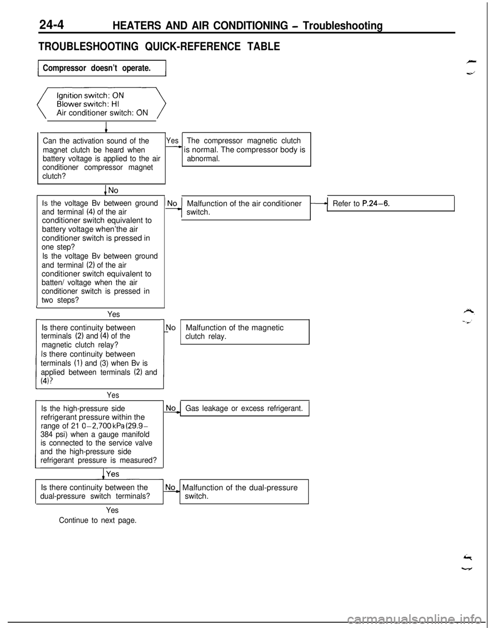
TROUBLESHOOTING QUICK-REFERENCE TABLE
Compressor doesn’t operate.Air conditioner switch: ON
1
Can the activation sound of theYesThe compressor magnetic clutch
magnet clutch be heard when
- is normal. The compressor body is
battery voltage is applied to the airabnormal.
conditioner compressor magnet
clutch?
Is the voltage Bv between ground
and terminal
(4) of the airconditioner switch equivalent to
battery voltage when’the air
conditioner switch is pressed in
one step?
Is the voltage Bv between ground
and terminal
(2) of the airconditioner switch equivalent to
batten/ voltage when the air
conditioner switch is pressed in
two steps?
YesIs there continuity between
terminals (2) and (4) of the
magnetic clutch relay?
Is there continuity between
terminals (1) and (3) when Bv is
applied between terminals
(2) and
(4)?
L
i
I
Yes
Is the high-pressure siderefrigerant pressure within the
range of 21 O-2,700 kPa (29.9-
384 psi) when a gauge manifold
is connected to the service valve
and the high-pressure side
refrigerant pressure is measured?
/YesMalfunction of the air conditioner
switch.
Refer to P.24-6.
r
1!
\loMalfunction of the magnetic
clutch relay.
Gas leakage or excess refrigerant.Is there continuity between the
dual-pressure switch terminals?
No_ Malfunction of the dual-pressure
switch.
Yes
Continue to next page.
Page 1150 of 1216

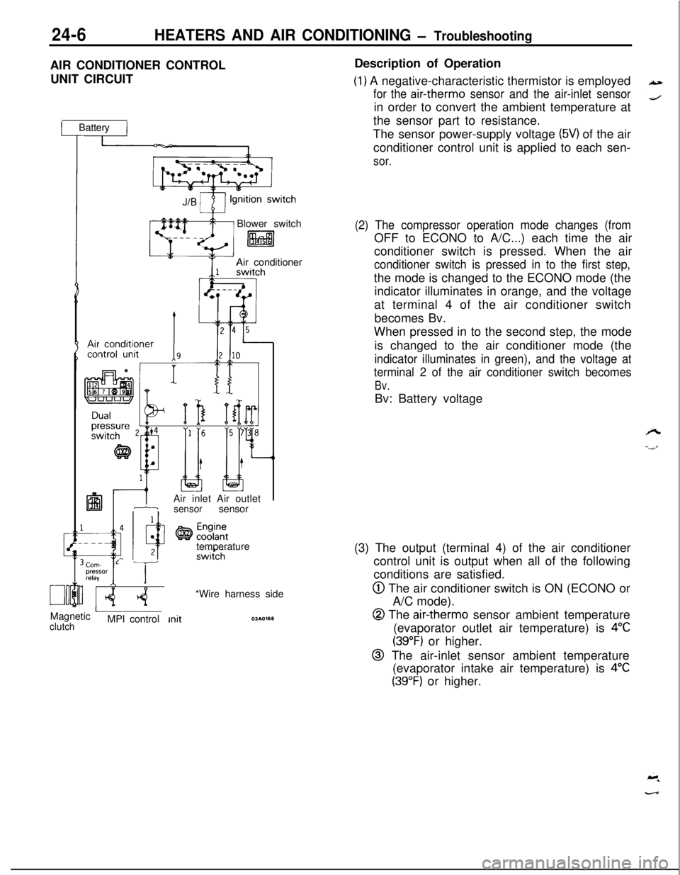
24-6HEATERS AND AIR CONDITIONING - TroubleshootingAIR CONDITIONER CONTROL
UNIT CIRCUIT
1 Battery IBlower switch
litalAir conditioner
IAir inlet Air outlet1-isensorsensor
temperature
Corn- L Tpressor
relayI IMagnetic
AclutchMPI control*Wire harness sideDescription of Operation
(1) A negative-characteristic thermistor is employed
for the air-therm0 sensor and the air-inlet sensorin order to convert the ambient temperature at
the sensor part to resistance.
The sensor power-supply voltage
(5V) of the air
conditioner control unit is applied to each sen-
sor.
(2) The compressor operation mode changes (fromOFF to ECONO to A/C...) each time the air
conditioner switch is pressed. When the air
conditioner switch is pressed in to the first step,the mode is changed to the ECONO mode (the
indicator illuminates in orange, and the voltage
at terminal 4 of the air conditioner switch
becomes Bv.
When pressed in to the second step, the mode
is changed to the air conditioner mode (the
indicator illuminates in green), and the voltage at
terminal 2 of the air conditioner switch becomes
Bv.Bv: Battery voltage
(3) The output (terminal 4) of the air conditioner
control unit is output when all of the following
conditions are satisfied.
@ The air conditioner switch is ON (ECONO or
A/C mode).
@ The air-therm0 sensor ambient temperature
(evaporator outlet air temperature) is
4°C
(39°F) or higher.
@ The air-inlet sensor ambient temperature
(evaporator intake air temperature) is
4°C
(39°F) or higher.
Page 1152 of 1216
24-8HEATERS AND AIR CONDITIONING - Troubleshooting
IARNESSES AND COMPONENTS LAYOUT DIAGRAM
1. Air conditioner switch
2. Air conditioner control unit
3. Air-inlet sensor
4.
Air-therm0 sensor
36AOO51
NameSymbolAir conditioner control unit
DAir conditioner switch
GAir inlet sensor
FAir
therm0 sensorFBlower motor High relay
E
IrrIor:enser fan motor High-Low selecting
C
NameCondenser fan motor relay
Dual pressure switch
Engine coolant temperature switch
<2.0L DOHC Engine>
Heater relay
Magnetic clutch relay
Symbol
C
BA
H
C
NOTEThe “Name” column is arranged in alphabetical order.
q \
q ---