1991 MITSUBISHI ECLIPSE check engine light
[x] Cancel search: check engine lightPage 170 of 1216
![MITSUBISHI ECLIPSE 1991 Service Manual 5-30BRAKES - Anti-lock Braking System Troubleshooting
BABS warning light illuminated after the engine is started and remains on.
[Explanation]This is the symptom when the ABS ECU does not
power up due MITSUBISHI ECLIPSE 1991 Service Manual 5-30BRAKES - Anti-lock Braking System Troubleshooting
BABS warning light illuminated after the engine is started and remains on.
[Explanation]This is the symptom when the ABS ECU does not
power up due](/manual-img/19/57104/w960_57104-169.png)
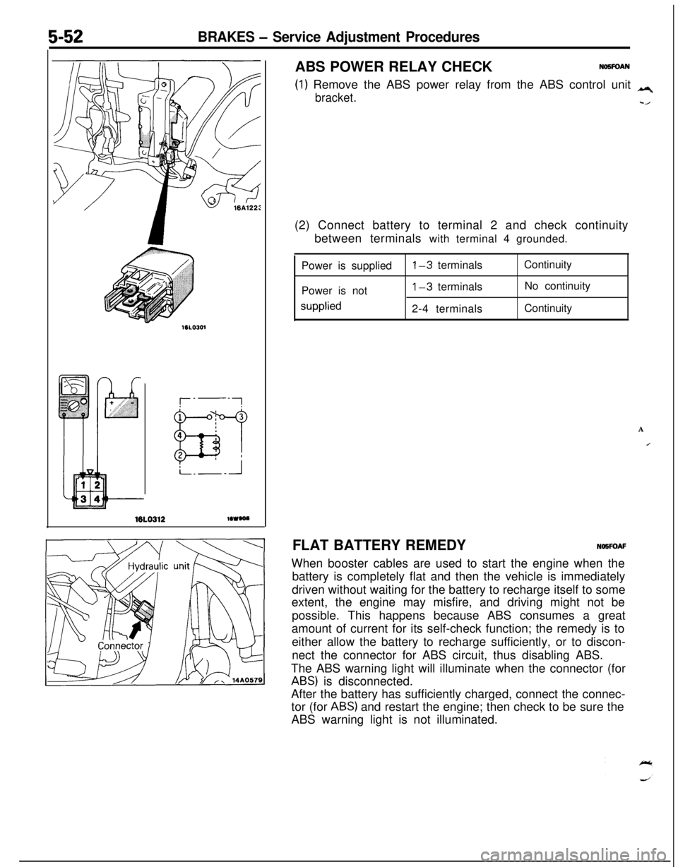
5-30BRAKES - Anti-lock Braking System Troubleshooting
BABS warning light illuminated after the engine is started and remains on.
[Explanation]This is the symptom when the ABS ECU does not
power up due to broken ECU power circuit, etc.,
when the fail safe function operates and isolates thesystem or when the warning light drive circuit is
short circuited.
MAINIGNITIONFUSIBLELINK
@SWITCH(IGl)
ABS ECU
JCheck, using check chart
E-l -E-7.with the ECU connector
dis-
YesDoes the ABS warning light
NoShort in HU harness or
remainilluminated even
with the ECU connector dis-m sticking of valve relay
contact
connected?I
YesReplace HU or replace
valve relay.
ItShort in harness between
IT$Uhx ECU and ABS warningc Repair harness or replace
combination meter.
Page 180 of 1216
![MITSUBISHI ECLIPSE 1991 Service Manual 5-40BRAKES - Anti-lock Braking System Troubleshooting
E-7Abnormality of motor drive circuit
[Explanation]The ABS ECU illuminates the warning light for the
motor relay and motor in the following cases. MITSUBISHI ECLIPSE 1991 Service Manual 5-40BRAKES - Anti-lock Braking System Troubleshooting
E-7Abnormality of motor drive circuit
[Explanation]The ABS ECU illuminates the warning light for the
motor relay and motor in the following cases.](/manual-img/19/57104/w960_57104-179.png)
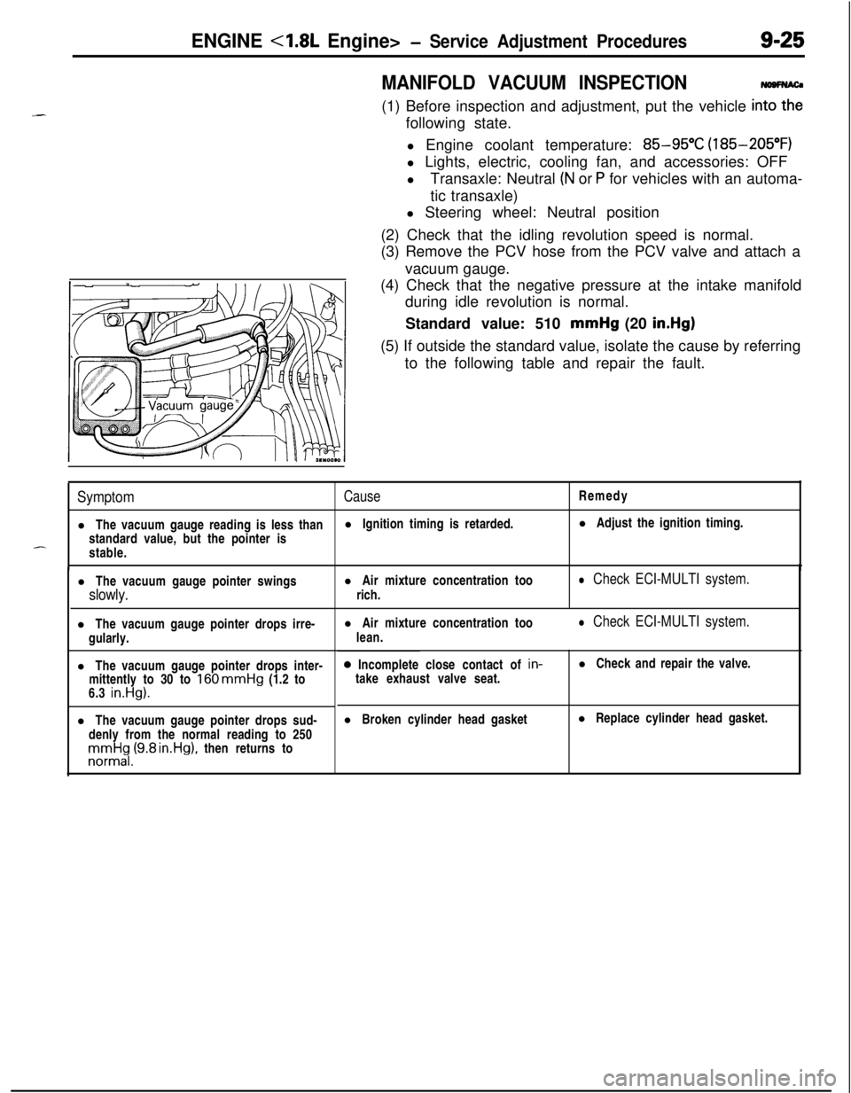
5-40BRAKES - Anti-lock Braking System Troubleshooting
E-7Abnormality of motor drive circuit
[Explanation]The ABS ECU illuminates the warning light for the
motor relay and motor in the following cases.
l When the motor relay does not function
lWhen there is trouble with the motor itself and it
does not revolve
[Hint]If there is motor operation noise when wheel speed
exceeds
Gkm/h (4mph) when starting up after the
engine is started, there is a broken or short circuitedmotor monitor wire.
lWhen the motor ground line is disconnected andthe motor does not revolve
l When the motor continues to revolve
Does the motor make a
YesBroken wire or short cir-noise when wheel speed
-cuit in motor monitor line
exceeds 6 km/h (4 mph)?
b
NoRepair the harness between HU and ECU.
emove the motor rela
ABS ECU
14A0105
Remove the motor relav and
check resistance values.
No.
85-No. 86:resistancevalue 30-60 QNo.30-No.87: no continui-
ty
Battery voltage is applied on
terminals No. 86 and No. 85
grounded
No. 30-No. 87: continuity
Yes
q Motor relay malfunction 1
Replace motor relay.I
Is pump motor ground con-netted normally?Connect ground wire.I
b
Does voltage between bodyNo
connector terminal 51 andIBroken wire in pumpmotor power circuit
ground indicate battery vol-
tage?1Repair the harness.
YesIs resistance between body
- No L Malfunction of harness
connector terminal No. 2 andbetween HU and ECU
No.26 30-60 ohms?b
YesRepair harness.
Motor drive circuit is normal.
Page 181 of 1216

BRAKES - Service Adjustment Procedures5-47switch
switch
v14F516
Idown ,./
F14517
F14518
F14519
SERVICE ADJUSTMENT PROCEDURES
BRAKE PEDAL INSPECTION AND ADJUSTM&g
1.Measure the brake pedal height as illustrated. If the brake
pedal height is not within the standard value, adjust as
follows.
Standard value (A): 176181 mm (6.9-7.1 in.)(1) Disconnect the stop light switch connector, loosen the
lock nut, and move the stop light switch to a position
where it does not contact the brake pedal arm.
(2) Adjust the brake pedal height by turning the operating
rod with pliers (with the operating rod lock nut
loosened), until the correct brake pedal height is
obtained.(3) After screwing in the stop light switch until it contacts
the brake pedal stopper (just before the brake pedal is
caused to move), return the stop light switch
l/2 to 1turn and secure by tightening the lock nut.
(4) Connect the connector of the stop light switch.
(5) Check to be sure that the stop light is not illuminated
with the brake pedal unpressed.
Reference value (B): 0.5-1.0 mm
(.02-M in.)
2. With the engine stopped, depress the brake pedal two or
three times. After eliminating the vacuum in the power
brake booster, press the pedal down by hand, and confirmthat the amount of movement before resistance is met
(the free play) is within the standard value range.
Standard value
(C): 3-8 mm (.l-.3 in.)
If the free play is less than the standard value, confirm thatthe clearance between the stop light switch and brake
pedal is within the standard value.
If the free play exceeds the standard value, it is probably
due to excessive play between the
clevis pin and brake
pedal arm. Check for excessive clearance and replace
faulty parts as required.
3. Start the engine, depress the brake pedal with approxi-
mately 500 N (110 Ibs.) of force, and measure the clearancebetween the brake pedal and the floorboard.
Standard value (D): 80 mm (3.1 in.) or moreIf the clearance is less than the standard value, check for
air trapped in the brake line and for brake fluid leaks. If
necessary, check the brake system mechanism (excessiveshoe clearance due to faulty auto adjuster) and repair
faulty parts as required.
Page 183 of 1216

BRAKES - Service Adjustment Procedures5-43When engine is
stoppedNo good
0
wtwo061
VV;Videngine is
t4uoo60
Caution
If the number of brake lever notches engaged is less
than the standard value, the cable has been pulledexcessively, and failure of the automatic adjuster
mechanism will result. Be sure tti adjust it to within the
standard value.(6) After making the adjustment, check to be sure that there is
no play between the adjusting nut and the pin. Also check
to be sure that the adjusting nut is securely held at the nut
holder.(7) After adjusting the lever stroke, jack up the rear of the
vehicle.(8) With the parking brake lever in the released position, turn
the rear wheel to confirm that the rear brakes are not
dragging.
PARKING BRAKE SWITCH CHECKN05FDAB
(1) Disconnect the connector of the parking brake switch, and
connect an ohmmeter to the parking brake switch and the
switch installation bolt.
(2) The parking brake switch is good if there is continuity whenthe parking brake lever is pulled and there is no continuity
when it is returned.
BRAKE BOOSTER OPERATING
lNSPECTIONNoSFcuFor simple checking of brake booster operation, carry out the
following tests.
(1) Run the engine for one or two minutes, and then stop it.
(2) Step on the brake pedal several times with normal
pressure.If the pedal depressed fully the first time. but gradually
becomes higher when depressed succeeding times, the
booster is operating properly.
If the pedal height remains unchanged, the booster is
faulty.(3) With the engine stopped, step on the brake pedal several
times with the same pressure to make sure that the pedal
height will not change.
Then step on the brake pedal and start the engine.
If the pedal moves downward slightly, the booster is in
good condition. If there is no change, the booster is faulty.
(4) With the engine running, step on the brake pedal and then
stop the engine.
Hold the pedal depressed for 30 seconds. If the pedal
height does not change, the booster is in good condition.
If the pedal rises, the booster is faulty.
If the above three tests are okay, the booster performance canbe determined as good.
If one of the above three tests is not okay at last, the check
valve, vacuum hose, or booster will be faulty.
Page 192 of 1216

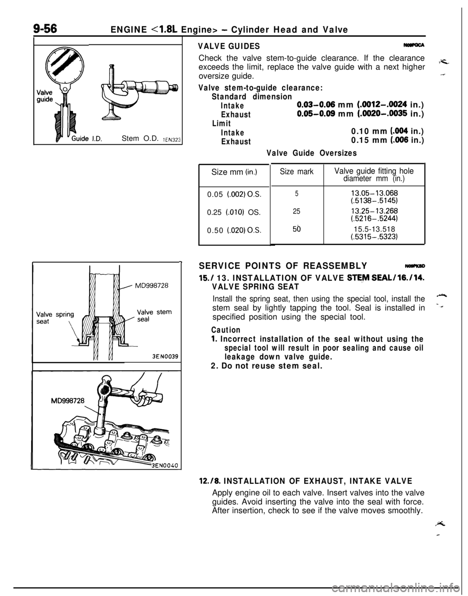
5-52BRAKES - Service Adjustment Procedures
16LO312lOWOO
(1) Remove the ABS power relay from the ABS control unit q
bracket.-/ABS POWER RELAY CHECK
NO5FOAN(2) Connect battery to terminal 2 and check continuity
between terminals with terminal 4 grounded.
Power is supplied
Power is not
supplied
l-3 terminals
1-3 terminals
2-4 terminalsContinuity
No continuity
Continuity
A
IFLAT BATTERY REMEDYNOWOAF
When booster cables are used to start the engine when the
battery is completely flat and then the vehicle is immediately
driven without waiting for the battery to recharge itself to some
extent, the engine may misfire, and driving might not be
possible. This happens because ABS consumes a great
amount of current for its self-check function; the remedy is to
either allow the battery to recharge sufficiently, or to discon-
nect the connector for ABS circuit, thus disabling ABS.
The ABS warning light will illuminate when the connector (for
ABS) is disconnected.
After the battery has sufficiently charged, connect the connec-
tor (for
ABS) and restart the engine; then check to be sure the
ABS warning light is not illuminated.
Page 309 of 1216

ENGINE <1.8L Engine>- Service Adjustment Procedures9-25
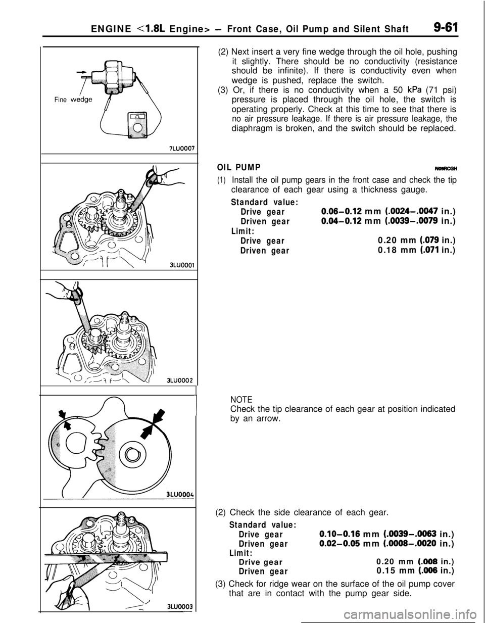
MANIFOLD VACUUM INSPECTION(1) Before inspection and adjustment, put the vehicle
in=following state.
l Engine coolant temperature:
85-95°C (185-205°F)
l Lights, electric, cooling fan, and accessories: OFF
lTransaxle: Neutral
(N or P for vehicles with an automa-
tic transaxle)
l Steering wheel: Neutral position
(2) Check that the idling revolution speed is normal.
(3) Remove the PCV hose from the PCV valve and attach a
vacuum gauge.
(4) Check that the negative pressure at the intake manifold
during idle revolution is normal.
Standard value: 510 mmHg (20
in.Hg)(5) If outside the standard value, isolate the cause by referring
to the following table and repair the fault.
SymptomCauseRemedy
l The vacuum gauge reading is less thanl Ignition timing is retarded.l Adjust the ignition timing.
standard value, but the pointer is
-stable.
l The vacuum gauge pointer swingsl Air mixture concentration too
slowly.rich.
l Check ECI-MULTI system.l The vacuum gauge pointer drops irre-
gularly.
l The vacuum gauge pointer drops inter-
mittently to 30 to
160 mmHg (1.2 to
6.3 in.Hg).l The vacuum gauge pointer drops sud-
denly from the normal reading to 250rronnrt$,(9.8 rn.Hg), then returns tol Air mixture concentration too
lean.
l Check ECI-MULTI system.0 Incomplete close contact of in-
take exhaust valve seat.l Check and repair the valve.
l Broken cylinder head gasketl Replace cylinder head gasket.
Page 340 of 1216

9-56ENGINE <1.8L Engine> - Cylinder Head and ValveStem O.D.
YEN323
3EN0039
-I
VALVE GUIDESCheck the valve stem-to-guide clearance. If the clearance
exceeds the limit, replace the valve guide with a next higher
7-c.oversize guide.“I
Valve stem-to-guide clearance:
Standard dimension
Intake0.03-0.06 mm (.0012-.0024 in.)
Exhaust0.05-0.08 mm (.0020-.0035 in.)
Limit
Intake0.10 mm (004 in.)
Exhaust0.15 mm (.006 in.)
Valve Guide OversizesSize mm
(in.)0.05
l.002) OS.0.25
LOlO) OS.
0.50
i.020) OS.
Size markValve guide fitting holediameter mm (in.)
513.05-13.068(.5138-.5145)
2513.25-13.268(.5216-.5244)
5015.5-13.518(.5315-.5323)
SERVICE POINTS OF REASSEMBLY
15./ 13. INSTALLATION OF VALVE STE,M SEAL/l6./14.
VALVE SPRING SEAT
Install the spring seat, then using the special tool, install the-stem seal by lightly tapping the tool. Seal is installed in
-dspecified position using the special tool.
Caution
1. Incorrect installation of the seal without using the
special tool will result in poor sealing and cause oil
leakage down valve guide.
2. Do not reuse stem seal.
12.18. INSTALLATION OF EXHAUST, INTAKE VALVEApply engine oil to each valve. Insert valves into the valve
guides. Avoid inserting the valve into the seal with force.
After insertion, check to see if the valve moves smoothly.PL
Page 345 of 1216

ENGINE <1.8L Engine> -Front Case, Oil Pump and Silent Shaft9-61
Fine
7LUOOO7
3LUOOOl
3LUOOO2
I
1(2) Next insert a very fine wedge through the oil hole, pushing
it slightly. There should be no conductivity (resistance
should be infinite). If there is conductivity even when
wedge is pushed, replace the switch.
(3) Or, if there is no conductivity when a 50
kPa (71 psi)
pressure is placed through the oil hole, the switch is
operating properly. Check at this time to see that there is
no air pressure leakage. If there is air pressure leakage, thediaphragm is broken, and the switch should be replaced.
OIL PUMPNomcGH
(1)Install the oil pump gears in the front case and check the tipclearance of each gear using a thickness gauge.
Standard value:
Drive gear
0.06-0.12 mm (.0024-.0047 in.)
Driven gear0.04-0.12 mm (.0039-.0079 in.)
Limit:
Drive gear0.20 mm (.079 in.)
Driven gear0.18 mm (.071 in.)
NOTECheck the tip clearance of each gear at position indicated
by an arrow.
(2) Check the side clearance of each gear.
Standard value:
Drive gear
0.10-0.16 mm (.0039-.0063 in.)
Driven gear0.02-0.05 mm (.0008-.0020 in.)
Limit:Drive gear0.20 mm (308 in.)
Driven gear0.15 mm (AI66 in.)(3) Check for ridge wear on the surface of the oil pump cover
that are in contact with the pump gear side.