55-10 HEATERS AND MANUAL AIR CONDITIONER -Service Adjustment Procedures
OFF-----__-__1210235 2,1002,700
(30) (33)(299) (384)
Pressure Fil
2OPOOlL
SERVICE ADJUSTMENT PROCEDURES
M55FEAU
TEST PROCEDURESSIGHT GLASS REFRIGERANT LEVEL TEST
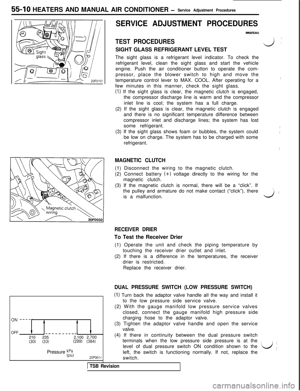
The sight glass is a refrigerant level indicator. To check the
refrigerant level, clean the sight glass and start the vehicle
engine. Push the air conditioner button to operate the com-
pressor, place the blower switch to high and move the
temperature control lever to MAX. COOL. After operating for a
few minutes in this manner, check the sight glass.
(I) If the sight glass is clear, the magnetic clutch is engaged,
the compressor discharge line is warm and the compressor
inlet line is cool; the system has a full charge.
(2) If the sight glass is clear, the magnetic clutch is engaged
and there is no significant temperature difference between
compressor inlet and discharge lines; the system has lost
some refrigerant.
(3) If the sight glass shows foam or bubbles, the system could
be low on charge. The system has to be charged with some
refrigerant.
MAGNETIC CLUTCH(1) Disconnect the wiring to the magnetic clutch.
(2) Connect battery (+) voltage directly to the wiring for the
magnetic clutch.
(3) If the magnetic clutch is normal, there will be a “click”. If
the pulley and armature do not make contact (“click”), there
is a malfunction.
v):
I
I
I
I
\,
3’
RECEIVER DRIERTo Test the Receiver Drier
(1) Operate the unit and check the piping temperature by
touching the receiver drier outlet and inlet.
(2) If there is a difference in the temperatures, the receiver
drier is restricted.
Replace the receiver drier.
DUAL PRESSURE SWITCH (LOW PRESSURE SWITCH)
(I) Turn back the adaptor valve handle all the way and install it
to the low pressure side service valve.
(2) With the gauge manifold low pressure service valves
closed, connect the gauge manifold high pressure side
charging hose to the adaptor valve.
(3) Tighten the adaptor valve handle and open the service
valve.
(4) If there in continuity between the dual pressure switch
terminals when the low pressure side pressure is at the
level of dual pressure switch ON condition shown to the
left, the switch is functioning normally. If not, replace the
L/(switch.
1 TSB Revision