Page 879 of 1146
BODY - Troubleshooting42-7
i
/
I/
i
POWER WINDOW
CIRCUIT DIAGRAMFUSIBLELINK@
POWERWINDOWS.RELAYC-07Xm
IR-B
%,,5,,l,\/\
-__------------
v
"43m
I,:
2F7
IIIII/IIIIIII,IIIIIIIIIIIII
_____ ---._-- .----------------------------- ----. ---
E-34
POWER WINDOW
MAIN SWITCH
------1r
L-
ETACS IJNIT
16 E-32
(RH)
(LH)(RH)----v--H
POWER WINDOW MOTOR
M42EBEGTSB Revision
Page 882 of 1146
42-10
BODY - Troubleshooting
CENTRAL DOOR LOCKING SYSTEM
CIRCUIT DIAGRAM
E-22 2If
J/V .L.L
g:s
B
,-4
Im
>;E
*Al g7=A%Ei
2019151817,---~~--~~-------.---- _____I ,--,L-,
ILIZ=I
35-AC-Rll02-NU
M42EBFHI
DOOR LOCK
POWER RELAY
J
E-13
%l:VEHICLES WITHOUT POWER WINDOWX2:VEHICLES WITH POWER WINDOW
\,3~
I
I
>dTSB RevisionI
Page 943 of 1146
EXTERIOR - Troubleshooting51-5
TROUBLESHOOTING
LWINDSHIELD WIPER AND WASHER
CIRCUIT DIAGRAMIGNITION :
i
ir
FRONT
KmYE7
-I--l--r-I-ii .
@
15A--
----
JUMPER
CONNECTOR
A-11X
Ea
d
53----
1
i4
CT
C-79
S&~DIAGNOSIS
CONNECTOR
EB'p%Jg@
g:f;:[pm1
:X35-AC-R1301-NY.:1
~;x2,--f-l--13L1------ ----- ---- ------ -7 q’,
I i
15:2 $x2
~-fi5
x3lTX2 pi2k%hw, :2~
3r,. I-EIv
s.LIjWl z
COLUMNn11 SWITCH C-113
MITTENTFROiiFRONTI IWIPER RELAYWIPER SWITCIII 1WASHER_SWITCHTI
34
TMSlKHBM
fITCH(ACC)
6LOll"FAST
VARIABLEINTERMITTENTo
WIPER
CONTROL
SWITCH
1 TSB Revision
Page 946 of 1146
51-8
EXTERIOR - Troubleshooting
CIRCUIT DIAGRAM
IGNITION IiITCH(ACC)TAILLIC
3
I
F0.
REAR0
INTERMITTENTc15A
IWIPER RELAYI
E-1836
1417
16_----_-----_-- ----__
CL
t1
3
23J&m
0;
3
%x4/X7/\/\
I~
I
I
I
I
I~
I
I
‘4 i
T RELAY
C-82
1
DEDICATEDFUSE
0.85Ld
3 C-69
1
J/Bii+m
d1
8 C-71
L
ii?m
d
8 D-44
3
REAR
LmFi/ILL6
80
I
iim
6 O.------
5
,,8
D-42
-1
RHEOSTAT
2
REAR
iii%~~R
F-15 F-34pLi%Fq2 D-41
idm
d
I
1m
I
REAR
WIPER
MOTOR
F-03
w123
b5-AC-RlJOE-NYTSB Revision
Page 947 of 1146

EXTERIOR - Troubleshooting
i.l
L
ELECTRIC REMOTE CONTROLLED MIRRORMSlEBBFCIRCUIT DIAGRAM
BEI
LLIfs
9LF?
PWATED
1
@iOA
w&
:ERIGNITIONSWITCH(ACC)-I
d
4
J/B
@ ::::15A
9
C-82
m
$i$iiq
:I1I’II
,IIIIIIII
IttI
1II,I
IIII
IIIt,
---------------------2 2
f
D-42
'-14
7
83296m9
-?;'9:c:a > c3> u,
REMOTEfjI#;"o;LLE'
EFti
tIL-------------q+1~-I~---------------------)L13w
.D-43 ‘1'8--- ---- ------------------ +’'7at2 D-41
/liRmqtI.) El::
:
1
(LH)(RH)
REMOTEiy;;I$)LLED:l:VEHICLES WITH MIRROR HEATERKXS-AC-R13C3-NYX2:VEHICLES WITHOUT MIRROR HEATEFOPERATION
l When the remote controlled mirror switch is
operated while the ignition key is in “ACC” or
“ON” position, current flows through fuse No.@ remote controlled mirror switch, remote
controlled mirror,remote controlled mirror
switch, and ground, causing the mirror to move.TROUBLESHOOTING HINTS
Neither right nor left mirror operates
1) Also cigarette lighter does not operate
l Check multi-purpose fuse No.
0.2) Cigarette lighter operates
l Check remote controlled mirror switch.
TSB Revision
Page 980 of 1146
52A-2INTERIOR - Troubleshooting
TROUBLESHOOTING
‘OWER SEATCIRCUIT DIAGRAMMSZEBHA
dl
IGNI'SWITl3
I
kt
C-82
J/B
i
0
15A
C-80
p77ziFq
ON(IGl)TII-I
/
,\777
"3
FUSIB ELINK Qb
m
3
123 c-01
lm456
'1
4
m
%
__---_----_i
1 TSB RevisionII
Page 982 of 1146
INTERIOR - Troubleshootina
TENSION-REDUCER TYPE SEAT BELT
M52EBIACIRCUIT DIAGRAM
ON(IGIlFUSIBLE LiNK@Im
Ia
E?I
qEl2C-68 ,.l 'I/C I/“I u0
1OA015A
,XL
z C-80
i
1 c-77j1'121"14151sij[pER@gqi
C-Slm 3
pTE$i@
r
d
F-19 $6
E-26
@yiq
2
FRONT SEAT;;B; S;;Y$H
FRONT SEATE-14BELT SOLENOID
/EzJ(RH)(LH)
2
I
E-20
m
1
EFS?J---_-___-~~~~__---I
:2cpjX3cc351ck---------------j2_----1kC-65
pziEgqX'
mx2
IIII
I
I
06L----v-----------v ________ Y
7 16"7 14:'" Err1
>>& lo:20
c-?9 PI
SELF-DIAGNOSIS mCHECK CONNECTORat1:VEHTCT.F.S WiTHOUT
\ (RI%(LH) /
#jT m- @$;"LA"'4
*cl - \PxJTPI UC w+c.v,a,,,uhhu ,,ITH7.iREpp&JqH(35AC-RlSlO-NYDOOR SWITCH
;tjgFgiALARMTSB Revision
Page 1011 of 1146

528-l
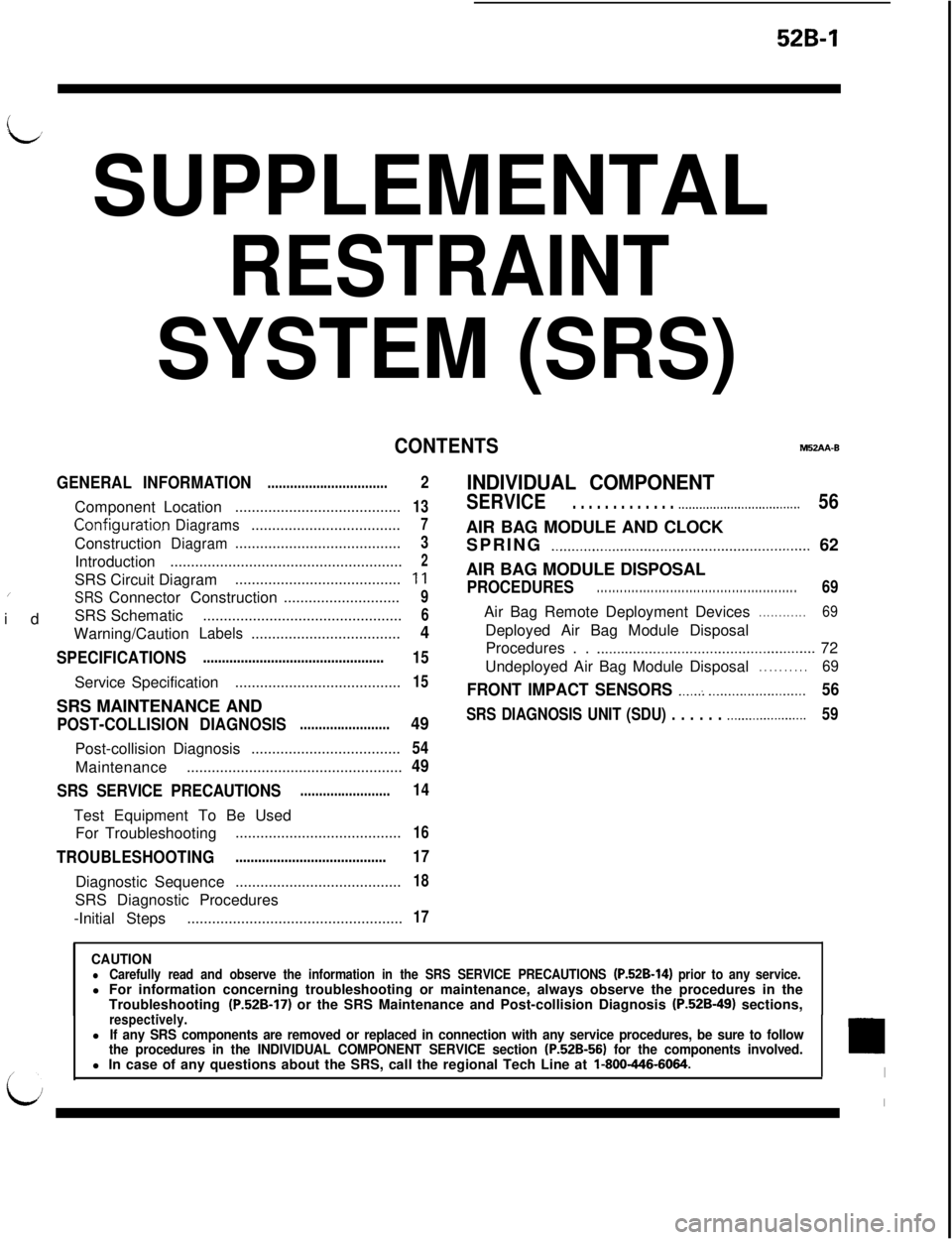
L’ SUPPLEMENTAL
RESTRAINT
SYSTEM (SRS)
CONTENTSM52AA-B
GENERAL INFORMATION
................................ComponentLocation
........................................
Configurati0.nDiagrams....................................Construction
Diagram........................................Introduction
........................................................SRS Circuit Diagram
......................................../idSRSConnector Construction............................SRS Schematic
................................................Warning/Caution
Labels....................................
SPECIFICATIONS................................................ServiceSpecification
........................................SRS MAINTENANCE AND
POST-COLLISION DIAGNOSIS........................Post-collisionDiagnosis
....................................Maintenance
....................................................
SRS SERVICE PRECAUTIONS........................Test Equipment To Be Used
For Troubleshooting
........................................
TROUBLESHOOTING........................................DiagnosticSequence
........................................SRS Diagnostic Procedures
-Initial Steps
....................................................
2
13
7
3
2
11
9
6
4
15
15
49
54
49
14
16
17
18
17
INDIVIDUAL COMPONENT
SERVICE. . . . . . . . . . . . . .._................................56AIR BAG MODULE AND CLOCK
SPRING
._..........._......................._.........._............... 62
AIR BAG MODULE DISPOSAL
PROCEDURES. . . . . . . . . . . . . . . . . . . . . . . . . . . . . . . . . . . . . . . . . . . . . . . . . . . .69Air Bag Remote Deployment Devices
. . . . . . . . . . . .69Deployed Air Bag Module Disposal
Procedures . .
.._..........._....................................... 72
Undeployed Air Bag Module Disposal
. . . . . . . . . .69
FRONT IMPACT SENSORS ._....: _._..._..................56
SRS DIAGNOSIS UNIT (SDU) . . . . . . .._...................59
CAUTIONlCarefully read and observe the information in the SRS SERVICE PRECAUTIONS (P.52B-14) prior to any service.l For information concerning troubleshooting or maintenance, always observe the procedures in the
Troubleshooting
(P.52B-17) or the SRS Maintenance and Post-collision Diagnosis (P.52B-49) sections,_respectively.lIf any SRS components are removed or replaced in connection with any service procedures, be sure to follow
the procedures in the INDIVIDUAL COMPONENT SERVICE section (P.52B-56) for the components involved.l In case of any questions about the SRS, call the regional Tech Line at l-800-446-6064.