Page 307 of 1146

COOLING - Water Pump, Water Pipe and Water Hose
WATER PUMP, WATER PIPE AND WATER HOSE
14-13
M14MB-B
/REMOVAL AND INSTALLATION
Pre-removal and Post-installation
Operation
l Draining and Supplying of the Engine Coolant
(Refer to GROUP 00 - Maintenance Service.)l Removal and Installation of Power Transistor
Unit and Ignition Coil
(Refer to GROUP 16 - Engine Electrical)l Removal and lnstallatlon of Timing Belt
(Refer to GROUP 11 -Timing Belt)17-20 Nm17-20 Nm
12-14ft.lbs.
1
12-15Nm9-11 ft.1bs.q
Removal steps
1. Water pump
2. Gasket
3. Air hose A
4. Air intake hose A
5. Air intake hose B
6. Air intake hose C
7. Air intake hose
8. Connection of radiator upper hose
9. Connection of water hose
IO. Water outlet fitting11. Gasket
12. Connection of harness
13. Connection of heater hose
14. Connection of water hose A
15. Connection of water hose
16. Connection of water hose
17. Connection of radiator lower hose
18. Connection of water hose
19. Thermostat housing
20. Gasket21.
Her water pipe22. O-ringOlFOO51
Installation steps
2. Gasket** 1. Water pumpI)+ 22. O-ring
l * 21. Inlet water pipe
20. Gasket
19. Thermostat housing18. Connection of water hose 17. Connection of radiator lower hose16. Connection of water hose
15. Connection of water hose
14. Connection of water hose A
13. Connection of heater h&e
12. Connection of harness11. Gasket10. Water outlet fitting
9. Connection of water hose
8. Connection of radiator upper hose7. Air intake hose l *6. Air Intake hose C **5. Air intake hose B l *4. Air intake hose A
3. Air hose A
TSB Revision
Page 308 of 1146

COOLING - Water Pump, Water Pipe and Water Hose
INSPECTION
WATER PUMP
I
MIQMDAOZIf any of the following irregularities are observed, replace the
LJwater pump as an assembly.
(1) Damage or crack on the water pump body
(2) Water leakage. With improper sealing, a water leakage
mark may be observed around hole
@.
,
(.31 x .98)OlLO188
6COO35
Air intake hose BOSFOO23
SERVICE POINTS OF INSTALLATION
1. INSTALLATION OF WATER PUMPM14MEAW
(1) Clean both gasket surfaces of water pump body and
cylinder block.
(2) Install new water pump gasket and water pump
assembly and tighten the bolts.
(3) Water pump installation bolt size are different and
caution must be paid to ensure that they are properly
installed.
22. INSTALLATION OF O-RING / 21. INLET WATER PIPEReplace the O-rings at both ends of the water inlet pipe
with new ones and apply water to the outside of O-rings to
help smooth insertion of the pipe into the water pump,.
thermostat housing.
CautionLJCare must be taken not to permit engine oil or
othergreases to adhere to the O-ring.
6.INSTALLATION OF AIR INTAKE HOSE C / 5. AIR INTAKEHOSE B
/ 4. AIR INTAKE HOSE A
Assemble the air intake hose A with its notches (arrow-
marked) lined up with the
D marks on the air intake hoses
B and C. Insert the hoses into the air intake hose A until
they are bottomed.
Insert the air intake hoses B and C on the turbocharger side
until they are bottomed.
TSB Revision
Page 309 of 1146
COOLINGEngine Coolant Temperature Gauge Unit, Engine Coolant- Temperature Sensor and Engine Coolant Temperature Switch14-15
ENGINE COOLANT TEMPERATURE GAUGE UNIT, ENGINE COOLANT
TEMPERATURE SENSOR AND ENGINE COOLANT TEMPERATURE
L,SWITCH
REMOVAL AND INSTALLATIONM140B. -Pre-removal and Post-installation
Operation
l Draining and Supplying of theEngine Coolant(Refer to GROUP 00 - MaintenanceService.)
30 NmOlFOO38
Removal steps
1. Air hose A l +2. Air intake hose A IF*3. Air intake hose B
4. Connection of radiator upper hose
5. Engine coolant temperature gauge unit
6. Engine coolant temperature sensor
(Engine control)7. Engine coolant temperature switch(Air conditioner)
INSPECTIONM140DAM
ENGINE COOLANT TEMPERATURE GAUGE UNITRefer to GROUP 54
- Meters and Gauges.
ENGINE COOLANT TEMPERATURE SENSOR (Engine con-
trol)Refer to GROUP 13
- MPI System Inspection.
TSB Revision
Page 310 of 1146

14-16
I
COOLINGEngine Coolant Temperature Gauge Unit, Engine Coolant- Temperature Sensor and Engine Coolant Temperature SwitchI
Air Intake hose B
05FOO2:
ENGINE COOLANT TEMPERATURE SWITCH (Air condition-I
4
(1) Immerse the engine coolant temperature switch in oil and
then heat (by using a gas stove flame or similar method) so
as to increase the oil temperature.
L.2~(2) Check to be sure that the engine coolant temperature
switch is switched OFF when the oil temperature reaches
the standard value.
Standard value: 112
- 118°C (234 - 244°F)
Caution
The oil used above should be engine oil and should be
stirred well while being heated; do not heat more than
necessary.
SERVICE POINTS OF INSTALLATIONM140EAz
3.INSTALLATION OF AIR INTAKE HOSE B / 2. AIR INTAKE
HOSE AB and L. Assemble the air intake hose A with its notches (arrow-
marked) lined up with the
n marks on the air intake hoses
. -dInsert the hoses Into the air intake hose A until they are
bottomed.
Insert the air intake hose B on the turbocharger side until
they are bottomed.
TSB Revision
Page 1099 of 1146

HEATERS AND MANUAL AIR CbNDlTlONER -Service Adjustment Procedures 55 17
ADJUSTMENT PROCEDURES(1) Select a quiet area for testing. Duplicate conditions as much
as possible. Switch compressor on and off several times to
clearly identify compressor noise.
To duplicate high ambient conditions (high head pressure),
restrict air flow through condenser. Install manifold gauge
set to make sure discharge pressure doesn’t exceed 2,070
kPa (300 psi).
(2) Tighten all compressor mounting bolts, clutch mounting
bolt, and compressor drive belt. Check to assure clutch coil
is tight (no rotation or wobble).
(3) Check refrigerant hoses for rubbing or interference that can
cause unusual noises.
(4) Check refrigerant charge. (See “Charging System”.)
(5) Recheck compressor noise as in Step 1.
(6) If noise still exists, loosen compressor mounting bolts and
retorque. Repeat Step 1.
(7) If noise continues, replace compressor and repeat Step 1.
POWER RELAY CHECKMBBFNAK(1) Remove the radiator fan motor relays (HI) and (LO) from the
relay box on the right of the engine compartment.
(2) Remove the radiator fan motor relay (air conditioner),
condenser fan motor relays (HI) and (LO), and
air-conditioner compressor relay from the relay box on the left
of the engine compartment.
(3) Remove the blower motor relay from the junction box.
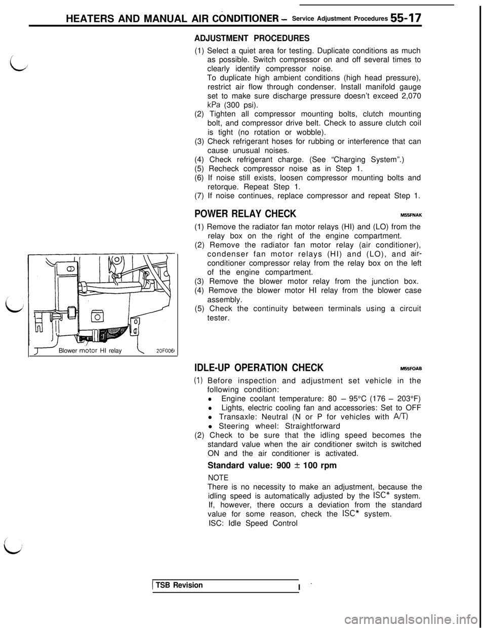
(4) Remove the blower motor HI relay from the blower case
assembly.
(5) Check the continuity between terminals using a circuit
tester.
J Blower m.otor HI relay\2OFOO6l
IDLE-UP OPERATION CHECKM55FOAB
(1) Before inspection and adjustment set vehicle in the
following condition:
lEngine coolant temperature: 80 - 95°C (176 - 203°F)
lLights, electric cooling fan and accessories: Set to OFF
l Transaxle: Neutral (N or P for vehicles with
A/T)l Steering wheel: Straightforward
(2) Check to be sure that the idling speed becomes the
standard value when the air conditioner switch is switched
ON and the air conditioner is activated.
Standard value: 900
+ 100 rpm
NOTEThere is no necessity to make an adjustment, because the
idling speed is automatically adjusted by the ISC” system.
If, however, there occurs a deviation from the standard
value for some reason, check the ISC” system.
ISC: Idle Speed Control
1 TSB RevisionI -
Page 1110 of 1146

55-28HEATERS AND MANUAL AIR CONDITIONER - Comtxessor
20F0067
SERVICE POINTS OF REMOVALM55SBAE1. REMOVAL OF COMPRESSOR DRIVE BELT
(1) Loosen bolt “A” for holding the tension pulley.
(2) Loosen bolt “B” for adjustment, and remove the
‘J
compressor drive belt.
3.REMOVAL OF SUCTION HOSE AND DISCHARGE HOSE
If the hoses are disconnected, cap the hoses with a blankplug to prevent entry of dust, dirt, and water.
5. REMOVAL OF COMPRESSOR
Caution
Lay the towel on the brake tube to protect them. When
install the compressor, do not damage the brake tubes.
This work must be done carefully so as not to spill the
compressor oil.
INSPECTIONM55SCAEl Checking for heat damage of the tension pulley.
l
Check for excessive play or deflection of the tension pulley.l Check for unusual wear of the tension pulley.
l Check for hardening of the air conditioner belt.
lCheck for unusual wear or abrasion of the air conditioner ,
belt.
\d’
OPERATION CHECK OF THE COMPRESSOR’S MAGNETIC
CLUTCH
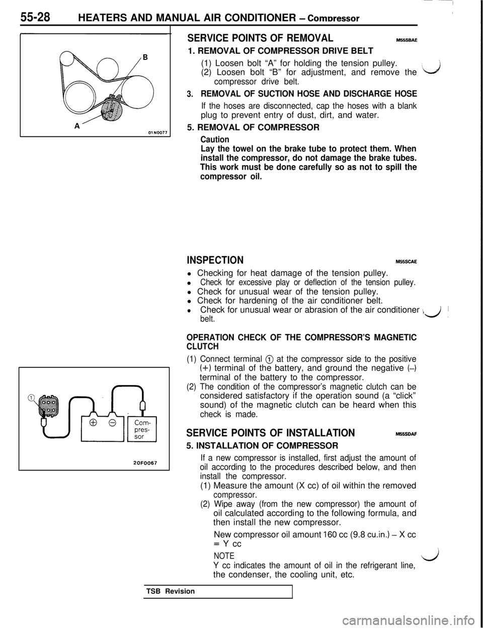
(1) Connect terminal @ at the compressor side to the positive
(+) terminal of the battery, and ground the negative (-)terminal of the battery to the compressor.
(2) The condition of the compressor’s magnetic clutch can beconsidered satisfactory if the operation sound (a “click”
sound) of the magnetic clutch can be heard when this
check is made.
SERVICE POINTS OF INSTALLATIONM55SDAF5. INSTALLATION OF COMPRESSOR
If a new compressor is installed, first adjust the amount of
oil according to the procedures described below, and then
install the compressor.(1) Measure the amount (X cc) of oil within the removed
compressor.
(2) Wipe away (from the new compressor) the amount ofoil calculated according to the following formula, and
then install the new compressor.
New compressor oil amount
160 cc (9.8 cu.in.) - X cc= Y cc
NOTE
Y cc indicates the amount of oil in the refrigerant line,l/jthe condenser, the cooling unit, etc.
TSB Revision